
Related Manuals for Celiera DUCTLESS MINI SPLIT AIR CONDITIONING SYSTEMS


Summary of Contents for Celiera DUCTLESS MINI SPLIT AIR CONDITIONING SYSTEMS
- Page 1 INSTRUCTION & INSTALLATION MANUAL DUCTLESS MINI SPLIT AIR CONDITIONING SYSTEMS © Céliera Corporation. All rights reserved. Unauthorized duplication, reproduction prohibited.
-
Page 2: Table Of Contents
CONTENTS SAFETY PRECAUTIONS..............1 NAMES OF THE PARTS..............3 INDOOR UNIT DISPLAY............... 4 EMERGENCY FUNCTION & AUTO-RESTART FUNCTION....5 REMOTE CONTROL..............6 MODES OF OPERATION............. 9 PROTECTION................14 INSTALLATION MANUAL.............. 15 MAINTENANCE................24 TROUBLESHOOTING..............25 In line with our policy of continual product improvement, the aesthetic and dimensional characteristics, technical data and acessories of this appliance may be changed without notice. -
Page 3: Safety Precautions
SAFETY RULES AND RECOMMENDATIONS FOR THE INSTALLER Read this guide before installing and using the Do not install the appliance closer than 50cm from appliance. flammable substances (alcohol, etc.) or pressurized containers (e.g. spray cans). During the installation of the indoor and outdoor units, access to the working area should be off limits to If the appliance is used in areas without the possibility children. - Page 4 SAFETY RULES AND RECOMMENDATIONS FOR THE USER This appliance has been made for air conditioning Disable automatic functions if you foresee not using domestic environments and must not be used for any the device for an extended period of time. The air flow other purpose, such as for drying clothing, cooling direction must also be properly adjusted.
-
Page 5: Names Of The Parts
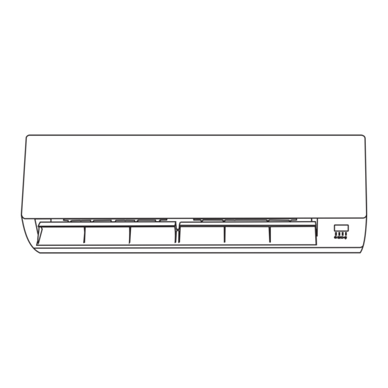
NAMES OF THE PARTS INDOOR UNIT Description Front Panel Air Filter Optional Filter (if installed) LED Display Signal Receiver Terminal Block Cover Ionizer Generator (if installed) Deflectors Emergency Button Indoor Unit Rating Label Airflow Direction Flaps Remote Control OUTDOOR UNIT Description Air Outlet Grille Outdoor Unit Rating Label... -
Page 6: Indoor Unit Display
INDOOR UNIT DISPLAY Function Shows that the unit is powered POWER SLEEP mode SLEEP Temperature display (if present) Indicates the set temperature in C° or F° TIMER TIMER mode Unit working... -
Page 7: Emergency Function & Auto-Restart Function
EMERGENCY FUNCTION AND AUTO-RESTART FUNCTION AUTO-RESTART FUNCTION The appliance comes equipped with a preset Auto- Restart function by the manufacturer. Using this function, the air conditioner can keep the selected settings after a blackout or a voltage drop. To deactivate the Auto-Restart function, perform the following: Emergency 1. -
Page 8: Remote Control
REMOTE CONTROL NOTE: The Remote controls all functions of the system. If it is lost, the system can still function using the EMERGENCY BUTTON, but certain functions will not be accessible. Setting Display ON/OFF Button Signal Transmitting Window Transmitting Icon Starts and stops operation Transmits signals to the system. -
Page 9: Remote Control Display
REMOTE CONTROL Remote Control Display Guide to LCD Symbols Symbols Indicator FEEL mode COOL mode DRY mode FAN ONLY mode HEATING mode TRANSMIT SIGNAL TIMER OFF TIMER ON AUTO FAN mode LOW FAN mode MEDIUM FAN mode HIGH FAN mode SLEEP mode FLAP SWING mode... -
Page 10: Preliminary Instructions
REMOTE CONTROL PROGRAMMING Preliminary Instructions How to Insert the Batteries • See Diagram 1: Remove the cover from the battery compartment by sliding it in the direction of the arrow. • Insert the new batteries, ensuring that the (+) and (-) symbols are correct. -
Page 11: Modes Of Operation
MODES OF OPERATION This air conditioner is designed to create a comfortable climate for individuals in the affected room. All models can cool and dehumidify the air completely Filter automatically and some models can also provide heat using either a heat pump or electric heat. Heat Air pulled by the fan enters through the grill of the front Exchanger... -
Page 12: Cooling Mode
MODES OF OPERATION COOLING MODE The cooling function allows the air conditioner to cool the room while dehumidifying the air at the same time. To activate the cooling function (COOL), press the MODE button until the symbol (COOL) appears on the LCD display. - Page 13 MODES OF OPERATION TIMER MODE - TIMER ON The TIMER function allows the system to automatically switch on. To set timed start, the system should be turned off. Press TIMER, set the desired temperature by pressing the buttons. Press TIMER again and set the amount of time, again using the buttons.
-
Page 14: Fan Mode
MODES OF OPERATION FAN MODE The system can be set to run in FAN mode, providing ventilation only. To run the system in FAN mode, press the MODE button until the FAN symbol appears on the display. Pressing the FAN button while in this mode changes the fan speed to LOW, MEDIUM, HIGH, or AUTO. -
Page 15: Sleep Mode
MODES OF OPERATION FEEL MODE The initial default operating mode is FEEL. FEEL mode automatically adjusts the function of the system based on a temperature range. To set the air conditioner to FEEL mode, press the MODE button until the FEEL symbol appears on the display. -
Page 16: Protection
PROTECTION In the cases listed below, the built-in protective device may be tripped, causing the system to stop operation. For T1 Climate condition models: MODEL Outdoor air temperature is over 24° C Outdoor air temperature is below -7° C Heating Room temperature is over 27°... -
Page 17: Installation Manual
INSTALLATION MANUAL---Selecting the Installation Place INDOOR UNIT Install the indoor unit level on a strong wall that is not Mounting plate subject to vibrations. The inlet and outlet ports should not be obstructed:the air should be able to blow all over the room. Do not install the unit near a source of heat , steam,or flammable gas. - Page 18 INSTALLATION MANUAL---Installation of the Indoor unit Before starting installation, decide on the position of the indoor and outdoor units, taking into account the minim- um space required around the units Install the indoor unit in the room to be air conditio- ning, avoiding to install in corridors or communal areas.
- Page 19 INSTALLATION MANUAL---Installation of the Indoor unit Refrigerant piping connection The piping can be run in the 3 directions indicated by numbers in the picture . When the piping is run in direction 1or3, cut a notch along the groove on the side of the indoor unit with a cutter.
- Page 20 INSTALLATION MANUAL---Installation of the Indoor unit INSTALLATION OF THE INDOOR UNIT After having connected the pipe according to the instruc- Covered by vinyl tape tions, install the connection cables. Now install the drain refrigerant insulation pipe. After connection,lag the pipe, cables and drain pipe pipe sleeve connection...
- Page 21 INSTALLATION MANUAL---Installation of the outdoor unit ELECTRICAL CONNECTIONS wiring diagram on the back of the cover 1. Take the cover away. 2. Connect the cable wires to the terminal board using the same numbering as in the indoor unit. 3. For the electrical connections, see the wiring diagram on the back of the cover 4.
- Page 22 INSTALLATION MANUAL---Installation of the outdoor unit BLEEDING 3-way valve diagram The air and humidity left inside the refrigerant circulat- ion can cause compressor malfunction. After having co- connect to indoor unit nnected the indoor and outdoor units, bleed the air and humidity from the refrigerant circulation using a va- open position cuum pump.
- Page 23 INSTALLATION MANUAL---Information for the installer FIXED-SPEED TYPE 22/24k 28/30k 15/18k MODEL capacity (Btu/h) Liquid pipe diameter ( 6) ( 6) ( 6) ( 6) ( 9.52) ( 9.52) Gas pipe diameter ( 9.52) ( 9.52) ( 9.52) ( 12) ( 15.88) ( 15.88) Lenght of pipe with standard charge Maximum distance between indoor and outdoor unit...
- Page 24 INSTALLATION MANUAL---Information for the installer WIRING DIAGRAM FOR 9K-12K-18K-24K HEAT PUMP MODELS FOR 9K-12K-18K-24K COOLING ONLY MODELS 110V 220V INDOOR UNIT INDOOR UNIT OUTDOOR UNIT POWER SUPPLY POWER OUTDOOR UNIT SUPPLY Please see the pasted diagram instruction on the unit first Note: The cable wires hasbeen connected to the main PCB of indoor unit by manufacturer according to the model without terminal block, see the wiring diagram on the right part of the unit under the front panel and the back of the outdoor cover...
- Page 25 INSTALLATION MANUAL---Information for the installer CABLE WIRES SPECIFICATION 22/24k 28/30k 15/18k MODEL capacity (Btu/h) sectional area 1.0mm 1.0mm 1.6mm 1.6mm 2.0mm 2.0mm 2.6mm AWG10 AWG18 AWG18 AWG14 AWG14 AWG12 AWG12 Power supply cable 2.0mm 1.6mm 1.0mm 1.0mm 1.6mm 2.0mm 2.6mm AWG12 AWG10 AWG18...
-
Page 26: Maintenance
MAINTENANCE Periodic maintenance is essential for keeping your air conditioner efficient. Before carrying out any maintenance , disconnect the power supply by putting the installation on/ off switch to off . INDOOR UNIT ANTIDUST FILTERS 1. Open the front panel following the direction of the arrow 2. -
Page 27: Troubleshooting
TROUBLESHOOTING MALFUNCTION POSSIBLE CAUSES Power failure/plug pulled out Damaged indoor/outdoor unit fan motor Faulty compressor thermomagnetic circuit breaker The appliance does not Faulty protective device or fuses. operate Loose connections or plug pulled out It sometimes stops operating to protect the appliance. Voltage higher or lower than the voltage range Active TIMER-ON function Damaged electronic control board...
Need help?
Do you have a question about the DUCTLESS MINI SPLIT AIR CONDITIONING SYSTEMS and is the answer not in the manual?
Questions and answers
what are the indoor unit btu ratings?
The indoor unit BTU ratings for Celiera ductless mini split air conditioning systems include 7K, 9K, 12K, 15K, 16K, 18K, 22K, 24K, and 30K.
This answer is automatically generated
Why is EL and O1 on my split uni and is it too cold outside for the outside Union to come on?
The provided context does not define the meanings of the EL and O1 error codes, so their meanings cannot be determined. However, for heating mode, the outdoor unit may stop operating if the outdoor temperature is below -7°C. If the current outdoor temperature is below -7°C, then it is too cold for the unit to operate in heating mode.
This answer is automatically generated