
Related Manuals for Celiera KHP Series


Summary of Contents for Celiera KHP Series
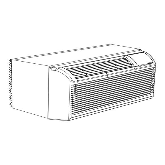
- Page 1 • KHP PTAC Units PACKAGED TERMINAL AIR CONDITIONER/HEAT PUMP Before using your air conditioner, please read this manual carefully and keep it for future reference.
- Page 2 CONTENTS 1. SAFETY PRECAUTIONS..............2 2. IMPORTANT SAFETY INSTRUCTIONS ..........4 3. AIR CONDITIONER FEATURES............5 4. CONTROL PANEL OPERATION............6 5. DIP SWITCHES CONFIGURATION...........8 6. INSTALLATION..................11 7. CARE AND CLEANING..............13 8. TROUBLESHOOTING...............14 Read This Manual Inside you will find many helpful hints on how to use and maintain your air conditioner properly.
- Page 3 SAFETY PRECAUTIONS To prevent injury to the user or other people and property damage, the following instructions must be followed. Incorrect operation due to ignoring of instructions may cause harm or damage. The seriousness is classified by the following indications. WARNING This symbol indicates the possibility of death or serious injury.
- Page 4 ! CAUTION When the air filter is to be Do not clean the air Ventilate the room well when removed, do not touch the conditioner with water. used together with a stove, metal parts of the unit. etc. It may cause an injury. Water may enter the unit and An oxygen shortage may occur.
- Page 5 IMPORTANT SAFETY INSTRUCTIONS For your safety WARNING NOTE The power supply cord with Do not store or use gasoline or other flammable vapors and liquids in this air conditioner contains a current the vicinity of this or any other appliance. detection device designed to reduce Avoid fire hazard or electric shock.
- Page 6 Operation of Current Device(optional) The power supply cord contains a current device that senses damage to the power cord. To test your power supply cord do the following: 1. Plug in the Air Conditioner. 2. The power supply cord will have TWO buttons on the plug head. Press the TEST button, you will notice a click as the RESET button pops out.
- Page 7 CONTROL PANEL OPERATION The control panel keypad will look like the following Note: If the unit has DIP SWITCHES feature,the temperature range can be setted is controlled by Fig.1. For some models with REMOTE SIGNAL DIP SWITCHES.See DIP SWITCHES CONFI- RECEPTOR, the unit can be controlled by the control GURATIONS on page 8 for details.
- Page 8 CONTROL PANEL OPERATION(CONTINUED) Accessory THIS UNIT IS CONTROLLED BY WALL MOUNTED THERMOSTAT NOTE:When the unit displays LC (Pads on the control panel is not available.The unit can be setted by using wire cotroller only.) You can install the Accessory on the control panel. NOTE: For some models, there is corresponding operation happened after 3 seconds when pressing any button.
- Page 9 DIP SWITCHES CONFIGURATIONS (Optional) REMOVING THE FRONT PANEL - Dip switches controls are located behind front panel, through an opening below the control panel.To access,remove front panel.See Fig.2. - Dip switches are accessible without opening the control box.See Fig.3. - Unit must be powered OFF to effectively change their status.
- Page 10 WALL THERMOSTAT TERMINAL (Optional) - Insert the wire connector of the wall t hermostat into IMPORTANT: Only trained, qualified personnel the relevant terminal according to different shapes as should access electrical panel on unit and install shown below. electrical accessories. Please contact your local some types of wall Terminal of electrical contractor, dealer, or distributor for...
- Page 11 WALL THERMOSTAT TERMINAL (Optional) FRONT DESK CONTROL CAUTION The controller can handle a switch signal from FC(L) and FC(N) input, called front desk control. Input must be 24VAC. UNIT DAMAGE HAZARD If system doesn't receive a 24VAC signal, it will turn unit Failure to follow this caution may result in off;...
- Page 12 INSTALLATION HOW TO INSTALL THE UNIT Dimension of air conditioner CAUTION 1067mm/42inch There are sharp edges that can cause serious cuts. When lifting the air conditioner,it is HEAVY.Use 2 408mm/16inch people to lift. - For existing sleeve,you should measure the wall sleeve dimensions.
- Page 13 INSTALLATION(CONTINUED) UNIT INSTALLATION (CONTINUED) CAUTION - Rotate the vent control lever to either open or close the vent door.(See Fig.6) Do not put obstacles around air-inlet or inside of air-outlet of the unit, such as window curtain etc. Vent control lever Always insert the filter securely, clean filter once every two weeks as required.
- Page 14 CARE AND CLEANING - Removing Air Filter FRONT PANEL AND CASE - Turn unit off and disconnect power supply.To clean, 2 Air filters use water and a mild detergent.DO NOT use bleach and abrasivers.Some commercial cleaners may Pull up damage the plastic parts. OUTDOOR COIL - Coil on outdoor side of unit should be checked regularly.Unit will need to be removed to inspect...
- Page 15 TROUBLESHOOTING POSSIBLE CAUSES SOLUTONS UNIT DOES NOT START Check that plug is plugged securely in wall receptacle. Unit may have become unplugged Note:Plug has a test/reset button on it.Make sure that the plug has Fuse may have blown not tripped. Circuit breaker may have been tripped Replace the fuse.See Note 1.
- Page 16 Corporate Headquarters: 4051 Haggerty Rd West Bloomfield, MI 48323 USA T: +1 866-777-7071 M-F 10a-6p ET F: +1 248-363-7834 Service Center & Warranty Repairs Facility: 14850 Linwood St Detroit, MI 48238 USA The design and specifications are subject to change without prior notice for product improvement.
Need help?
Do you have a question about the KHP Series and is the answer not in the manual?
Questions and answers