Table of Contents
Advertisement
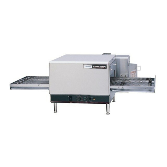
SERVICE MANUAL
IMPINGER COUNTERTOP OVEN
MODEL 1300 SERIES
Lincoln Foodservice Products, LLC
1111 North Hadley Road
Fort Wayne, Indiana 46804
United States of America
Phone : (800) 374-3004
U.S. Fax: (888) 790-8193 • Int'l Fax: (260) 436-0735
Technical Service Hot Line
(800) 678-9511
www.lincolnfp.com
1300svcman
REV: 7/02/07
Advertisement
Table of Contents

Related Manuals for Lincoln Impinger


Summary of Contents for Lincoln Impinger
- Page 1 SERVICE MANUAL IMPINGER COUNTERTOP OVEN MODEL 1300 SERIES Lincoln Foodservice Products, LLC 1111 North Hadley Road Fort Wayne, Indiana 46804 United States of America Phone : (800) 374-3004 U.S. Fax: (888) 790-8193 • Int’l Fax: (260) 436-0735 Technical Service Hot Line (800) 678-9511 www.lincolnfp.com...
-
Page 2: Table Of Contents
SERVICE AND PARTS MANUAL 1300 SERIES IMPINGER COUNTERTOP OVEN TABLE OF CONTENTS TABLE OF CONTENTS..............................2 SEQUENCE OF OPERATIONS..........................3 SCHEMATIC 1301, 1302 S/N 3000352 & BELOW ....................5 SCHEMATIC 1301, 1302 S/N 3000353 TO 3000480.....................6 SCHEMATIC 1300, 1301, 1302, 1310 S/N 3000481 TO 3018980 ................7 SCHEMATIC 1300, 1301, 1302, 1310 S/N 3018981 -3022633 ................8... -
Page 3: Sequence Of Operations
SEQUENCE OF OPERATIONS MODEL CTI 1300 200 VAC 60 HZ 1 PHASE 1301 208 VAC 60 HZ1 1 PHASE 1302 240 VAC 60 HZ 1 PHASE 1303 220 VAC 50 HZ 1 PHASE 1304 240 VAC 50 HZ 1 PHASE 1305 380/220 VAC 50 HZ... - Page 4 MAIN FAN CIRCUIT Electrical power is permanently supplied through the Control Box Hi-Limit to terminal one (1) of the 20- Minute Timer. When the DPST Fan Switch is closed, the timer is enabled. This energizes terminal two (2) of timer, which supplies power to the Coil of the Fan Relay and the Cooling Fan Motor. The normally open contacts of the Fan Relay now close energizing the Main Fan Motor.
-
Page 5: Schematic 1301, 1302 S/N 3000352 & Below
SCHEMATIC 1301, 1302 S/N 3000352 & BELOW CounterTop – 1300 Series Service Manual... -
Page 6: Schematic 1301, 1302 S/N 3000353 To 3000480
SCHEMATIC 1301, 1302 S/N 3000353 TO 3000480 CounterTop – 1300 Series Service Manual... -
Page 7: Schematic 1300,1301,1302,1310 S/N 3000481 To 3018980
SCHEMATIC 1300,1301,1302,1310 S/N 3000481 TO 3018980 CounterTop – 1300 Series Service Manual... -
Page 8: Schematic 1300,1301,1302,1310 S/N 3018981 -3022633
SCHEMATIC 1300,1301,1302,1310 S/N 3018981 –3022633 CounterTop – 1300 Series Service Manual... -
Page 9: Schematic 1300, 1301, 1301-4, 1302, 1302-4, 1310 S/N 3022634 To 3043630
SCHEMATIC 1300, 1301, 1301-4, 1302, 1302-4, 1310 S/N 3022634 TO 3043630 CounterTop – 1300 Series Service Manual... -
Page 10: Schematic 1300, 1301, 1301-4, 1302, 1302-4, 1310 S/N 3043631 & Above
SCHEMATIC 1300, 1301, 1301-4, 1302, 1302-4, 1310 S/N 3043631 & ABOVE CounterTop – 1300 Series Service Manual... -
Page 11: Schematic 1301-4, 1302-4 S/N 3018980 & Below
SCHEMATIC 1301-4, 1302-4 S/N 3018980 & BELOW CounterTop – 1300 Series Service Manual... -
Page 12: Schematic 1301-4, 1302-4 S/N 3018981 To 3043630
SCHEMATIC 1301-4, 1302-4 S/N 3018981 TO 3043630 CounterTop – 1300 Series Service Manual... -
Page 13: Schematic 1301-4, 1302-4 S/N 3043631 & Above
SCHEMATIC 1301-4, 1302-4 S/N 3043631 & ABOVE CounterTop – 1300 Series Service Manual... -
Page 14: Schematic 1303,1304 S/N 3018980 & Below
SCHEMATIC 1303,1304 S/N 3018980 & BELOW CounterTop – 1300 Series Service Manual... -
Page 15: Schematic 1303,1304 S/N 3018981 To 3043630
SCHEMATIC 1303,1304 S/N 3018981 TO 3043630 CounterTop – 1300 Series Service Manual... -
Page 16: Schematic 1303,1304 S/N 3043631 & Above
SCHEMATIC 1303,1304 S/N 3043631 & ABOVE CounterTop – 1300 Series Service Manual... -
Page 17: Schematic 1304-4 S/N 3018980 & Below
SCHEMATIC 1304-4 S/N 3018980 & BELOW CounterTop – 1300 Series Service Manual... -
Page 18: Schematic 1304-4 S/N 3018981 To 3043630
SCHEMATIC 1304-4 S/N 3018981 TO 3043630 CounterTop – 1300 Series Service Manual... -
Page 19: Schematic 1304-4 S/N 3043631 & Above
SCHEMATIC 1304-4 S/N 3043631 & ABOVE CounterTop – 1300 Series Service Manual... -
Page 20: Schematic 1305,1306 S/N 3018980 & Below
SCHEMATIC 1305,1306 S/N 3018980 & BELOW CounterTop – 1300 Series Service Manual... -
Page 21: Schematic 1305,1306 S/N 3018981 To 3043630
SCHEMATIC 1305,1306 S/N 3018981 TO 3043630 CounterTop – 1300 Series Service Manual... -
Page 22: Schematic 1305,1306 S/N 3043631 & Above
SCHEMATIC 1305,1306 S/N 3043631 & ABOVE CounterTop – 1300 Series Service Manual... -
Page 23: Schematic 1305-4 S/N 3018980 & Below
SCHEMATIC 1305-4 S/N 3018980 & BELOW CounterTop – 1300 Series Service Manual... -
Page 24: Schematic 1305-4 S/N 3018981 To 3043630
SCHEMATIC 1305-4 S/N 3018981 TO 3043630 CounterTop – 1300 Series Service Manual... -
Page 25: Schematic 1305-4 S/N 3043631 & Above
SCHEMATIC 1305-4 S/N 3043631 & ABOVE CounterTop – 1300 Series Service Manual... -
Page 26: Schematic 1307 S/N 3018980 & Below
SCHEMATIC 1307 S/N 3018980 & BELOW CounterTop – 1300 Series Service Manual... -
Page 27: Schematic 1307 S/N 3018981 To 3043630
SCHEMATIC 1307 S/N 3018981 TO 3043630 CounterTop – 1300 Series Service Manual... -
Page 28: Schematic 1307 S/N 3043631 & Above
SCHEMATIC 1307 S/N 3043631 & ABOVE CounterTop – 1300 Series Service Manual... -
Page 29: Schematic 1308,1309,1311 S/N 3018980 & Below
SCHEMATIC 1308,1309,1311 S/N 3018980 & BELOW CounterTop – 1300 Series Service Manual... -
Page 30: Schematic 1308,1309,1311 S/N 3018981 To 3043630
SCHEMATIC 1308,1309,1311 S/N 3018981 TO 3043630 CounterTop – 1300 Series Service Manual... -
Page 31: Schematic 1308,1309,1311 S/N 3043631 & Above
SCHEMATIC 1308,1309,1311 S/N 3043631 & ABOVE CounterTop – 1300 Series Service Manual... -
Page 32: Schematic 1308-4 S/N 3018980 & Below
SCHEMATIC 1308-4 S/N 3018980 & BELOW CounterTop – 1300 Series Service Manual... -
Page 33: Schematic 1308-4 S/N 3018981 To 3043630
SCHEMATIC 1308-4 S/N 3018981 TO 3043630 CounterTop – 1300 Series Service Manual... -
Page 34: Schematic 1308-4 S/N 3043631 & Above
SCHEMATIC 1308-4 S/N 3043631 & ABOVE CounterTop – 1300 Series Service Manual... -
Page 35: Schematic 1312-000-E S/N 3018980 & Below
SCHEMATIC 1312-000-E S/N 3018980 & BELOW CounterTop – 1300 Series Service Manual... -
Page 36: Schematic 1312-000-E S/N 3018981 & Above
SCHEMATIC 1312-000-E S/N 3018981 & ABOVE CounterTop – 1300 Series Service Manual... -
Page 37: Schematic 1313-000-E S/N 3018980 & Below
SCHEMATIC 1313-000-E S/N 3018980 & BELOW CounterTop – 1300 Series Service Manual... -
Page 38: Schematic 1313-000-E S/N 3018981 & Above
SCHEMATIC 1313-000-E S/N 3018981 & ABOVE CounterTop – 1300 Series Service Manual... -
Page 39: Schematic 1314-F24-E S/N 3018980 & Below
SCHEMATIC 1314-F24-E S/N 3018980 & BELOW CounterTop – 1300 Series Service Manual... -
Page 40: Schematic 1314-F24-E S/N 3018981 & Above
SCHEMATIC 1314-F24-E S/N 3018981 & ABOVE CounterTop – 1300 Series Service Manual... -
Page 41: Troubleshooting Guide
TROUBLESHOOTING GUIDE IMPINGER CTI SYMPTOM POSSIBLE CAUSE EVALUATION Oven fan will not run Incoming Power Supply Check breakers, reset if required Check power plug to be sure it is firmly in the receptacle (if applicable). Measure the incoming power, call Power Co., if... - Page 42 Oven will not heat Main Oven Fan Check if main oven fan is working. If not, refer to "Oven Fan Will Not Run". Temperature Control Check for voltage input at the board. Turn the Board temperature adjustment knob to the maximum temperature position and check for voltage at the load terminal.
- Page 43 Conveyor will not run Fan Switch Check continuity between switch terminals. Replace S/N 3000480 and Below as needed. Conveyor Control Check for supply voltage at primary of transformer. If Transformer no voltage is present, trace wiring back to fan switch. Check for 24VAC at transformer secondary.
- Page 44 Conveyor will not run Fan Switch WITH POWER OFF: Check continuity between switch (S/N 3000481 & Above) terminals. Check and insure good wire connections. Conveyor Control With the fan switch on, check for supply voltage at the Transformer primary of the transformer. Check for voltage on the secondary side of transformer (24 VAC) at J4 and J5 on the conveyor control board.
-
Page 45: Removal, Installation, And Adjustment
REMOVAL, INSTALLATION, AND ADJUSTMENT MODEL SERIES 1300 CAUTION! BEFORE REMOVING OR INSTALLING ANY COMPONENT IN THE IMPINGER OVEN BE SURE TO DISCONNECT ELECTRICAL POWER SUPPLY SWITCH, ON-OFF 1. Remove conveyor and oven side panels. 2. Remove two (2) screws from ends of control panel and remove panel. - Page 46 THERMOSTAT, OVEN CAVITY HI-LIMIT 1. Remove control box cover. 2. Remove oven back assembly. (See OVEN BACK) 3. Remove two (2) wires from thermostat. 4. Remove retaining nut from the front of thermostat and remove thermostat. 5. Remove capillary tube from wire form in back of oven and remove assembly out through control box side. 6.
- Page 47 MAIN FAN RELAY 1. Remove control box cover 2. Remove wires from relay and mark wires for reinstallation. 3. Remove two (2) screws and replace relay. 4. Reassemble in reverse order and check operation. TIME DELAY RELAY 1. Remove control box cover. 2.
-
Page 48: Conveyor Control Board - Replacement
ASSEMBLY OF MAGNET TO MOTOR FOR OVENS WITH 1-12 MINUTE CONVEYOR DRIVE SYSTEM 1. Apply 1 or 2 drops of adhesive (supplied) to magnet. Mount magnet on motor shaft. Be sure to keep adhesive away from motor bearings. NOTE: Use magnet marked "8" FOR OVENS WITH 1-24 MINUTE CONVEYOR DRIVE SYSTEM 1. - Page 49 177C/350F 240C/400F 450F/232C 149C/300F 121C/250F 500F/260C 93C/200F 550F/288C CALIBRATION MARK 5. Turn the temperature control knob to 500°F (260°C) and calibrate the temperature control board. Adjust the top potentiometer only (see diagram Pg. D5) so the unit cycles at 500°F ± 10°F (490°F - 510°F). 6.
- Page 50 COOLING FAN, CONTROL BOX 1. Remove control box cover. 2. Remove four (4) screws. 3. Lift off fan guard and finger guard. 4. Disconnect two wires and replace fan. 5. Reassemble in reverse order and check operation. NOTE: Check to insure that control box high limit switch is not tripped. Reset if needed. CAPACITOR, MOTOR 1.
- Page 51 THERMOCOUPLE 1. Remove control box cover. 2. Remove six (6) acorn nuts holding motor cover and remove. 3. Remove four (4) acorn nuts holding oven back assembly and remove oven back. 4. Remove thermocouple bulb from wire form in rear of oven cavity. 5.
- Page 52 HEATING ELEMENT (Color Coded on the Cold Zone) PART# 369418 Heating Element 208V PART# 369419 Heating Element 240V Blue PART# 369450 Heating Element 220V Yellow PART# 369455 Heating Element 200V Orange PART# 369456 Heating Element 380V Violet PART# 369457 Heating Element 415V Green PART# 369475 Heating Element 200V 3 PH...
- Page 53 This page intentionally left blank. CounterTop – 1300 Series Service Manual...
-
Page 54: General - 1300 Series
GENERAL – 1300 SERIES LETTER DESCRIPTION 369434 Air Duct Panel, Upper 369442 Finger Housing S/N 3002167 & Below 369436 Columnating Plate #2 (UR) – S/N 3002167 & Below 369445 Finger Cover, Upper Right – S/N 3002167 & Below 369441 Finger Cover, Lower Right – S/N 3002167 & Below 369439 Columnating Plate #4 (LR) –... -
Page 55: General - 1300 Series Parts Blow-Up
GENERAL – 1300 SERIES PARTS BLOW-UP NEW FINGER ASSEMBLY (S/N 3045308 & ABOVE) CounterTop – 1300 Series Service Manual... -
Page 56: Control Compartment - 1300 Series
CONTROL COMPARTMENT – 1300 SERIES LETTER DESCRIPTION 369426 Cooling Fan – S/N 3000399 & Below 369378 Cooling Fan – S/N 3000400 & Above 369428 Finger Guard – S/N 3000399 & Below 369331 Finger Guard – S/N 3000400 & Above 369415 Conveyor Control S/N 3000480 &... -
Page 57: Control Compartment - 1300 Series Blow - Up
CONTROL COMPARTMENT – 1300 SERIES BLOW - UP CounterTop – 1300 Series Service Manual... -
Page 58: Back - 1300 Series
BACK – 1300 SERIES LETTER DESCRIPTION Color Coded on The Cold Zone 369418 Heating Element - 208V 369419 Heating Element - 240V Blue 369450 Heating Element - 220V Yellow 369455 Heating Element - 200V Orange 369456 Heating Element - 380V Violet 370105 Heating Element - 400V 1 PH... -
Page 59: Back - 1300 Series Blow - Up
BACK – 1300 SERIES BLOW - UP CounterTop – 1300 Series Service Manual... -
Page 60: Standard Conveyor - 1300 Series
STANDARD CONVEYOR – 1300 SERIES LETTER DESCRIPTION 369443 Standard Complete Conveyor Assy. (31” Length) 369462 Idler Axle 369515 Drive Sprocket 369516 Conveyor Bearing 369463 Drive Axle 369471 Roll Pin, 5/32 x 7/8” 1343 Entry Shelf – 12” 1344 Entry Shelf – 4” 369412 Conveyor Splice Clip 369411... -
Page 61: Extended Conveyor - 1300 Series
EXTENDED CONVEYOR – 1300 SERIES LETTER DESCRIPTION 369909 Extended Conveyor Assy. (49 ¾” Length) 369462 Idler Axle 369515 Drive Sprocket 369516 Conveyor Bearing 369463 Drive Axle 369471 Roll Pin, 5/32 x 7/8” 369943 Conveyor Frame, Extended 369412 Conveyor Splice Clip 369481 Conveyor Belting –... - Page 62 This page intentionally left blank. CounterTop – 1300 Series Service Manual...
- Page 63 This page intentionally left blank. CounterTop – 1300 Series Service Manual...
- Page 64 Lincoln Foodservice Products, LLC 1111 North Hadley Road Fort Wayne, Indiana 46804 United States of America Phone : (800) 374-3004 U.S. Fax: (888) 790-8193 • Int’l Fax: (260) 436-0735 Technical Service Hot Line (800) 678-9511 www.lincolnfp.com CounterTop – 1300 Series Service Manual...