HP compaq Hardware Manual
Hide thumbs
Also See for compaq:
- Troubleshooting manual (68 pages) ,
- Startup manual (42 pages) ,
- Support manual (23 pages)
Table of Contents
Advertisement
Quick Links
Download this manual
See also:
Troubleshooting Manual
Hardware Guide
hp compaq notebook series
Document Part Number: 309971-001
April 2003
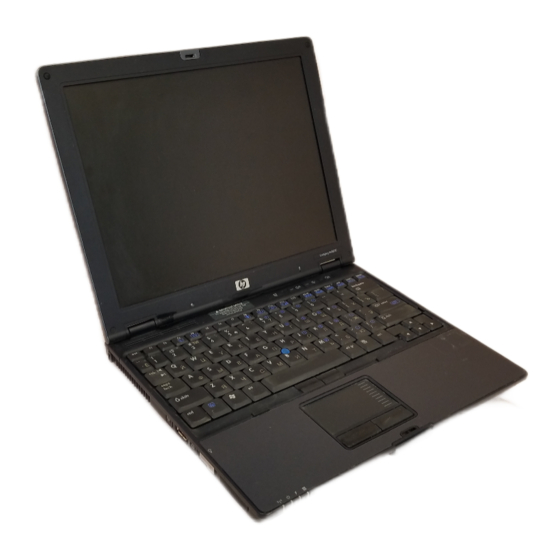
This guide explains how to identify and use notebook hardware
features, including connectors for external devices. It also
includes power and environmental specifications, which may be
helpful when traveling with the notebook.
Advertisement
Table of Contents

Related Manuals for HP compaq


Summary of Contents for HP compaq
- Page 1 Hardware Guide hp compaq notebook series Document Part Number: 309971-001 April 2003 This guide explains how to identify and use notebook hardware features, including connectors for external devices. It also includes power and environmental specifications, which may be helpful when traveling with the notebook.
- Page 2 Intel and SpeedStep are trademarks of Intel Corporation in the U.S. and/or other countries. SD Logo is a trademark. HP shall not be liable for technical or editorial errors or omissions contained herein or for incidental or consequential damages in connection with the furnishing, performance, or use of this material.
-
Page 3: Table Of Contents
Contents 1 Notebook Features Pointing Device Components..... . 1–1 Top Components ....... 1–3 Left Side Components . - Page 4 Contents Using Quick Launch Buttons ..... 2–10 Keypads ........2–11 Using the Internal Keypad.
- Page 5 Contents 5 Audio and Video Using Audio Features......5–1 Adjusting the Volume ......5–2 Using the Microphone Input Jack .
- Page 6 Contents 8 Hardware Upgrades Using PC Cards ....... . 8–1 Inserting a PC Card .
-
Page 7: Notebook Features
Notebook Features Pointing Device Components Pointing Device Components Item Component Description Pointing stick Moves the pointer and selects or activates items on the screen. Left and right pointing stick Function like the left and right buttons buttons on an external mouse. Hardware Guide 1–1... - Page 8 Notebook Features Pointing Device Components (Continued) Item Component Description TouchPad Moves the pointer and selects or activates items on the screen. Can be set to perform other mouse functions, such as scrolling and double-clicking. Left and right TouchPad Function like the left and right buttons buttons on an external mouse.
-
Page 9: Top Components
Notebook Features Top Components Top Components Item Component Description Quick Launch buttons (3) Enable you to access common functions with a single keystroke. Power button When the notebook is* ■ Off, press and release to turn on the notebook. ■ In Standby, press and release to exit Standby. - Page 10 Notebook Features Top Components (Continued) Item Component Description Volume control buttons Increase, decrease, and mute the system volume. Function keys Execute frequently used system functions when pressed in combination with the key. Applications key Displays shortcut menu for items beneath the pointer. Display release latch Secures the display when it is closed.
-
Page 11: Left Side Components
Notebook Features Left Side Components Left Side Components Item Component Description Infrared port Links another IrDA-compliant device for wireless communication. PC Card eject button Ejects an optional PC Card from the PC Card slot. PC Card slot Supports optional Type I or Type II 32-bit (CardBus) or 16-bit PC Cards. -
Page 12: Right Side Components
Notebook Features Right Side Components Right Side Components Item Component Description Security cable slot Attaches an optional security cable to the notebook. Hard drive bay Holds the primary hard drive. Exhaust vent Enables airflow to cool internal components. Ä To prevent overheating, do not obstruct vents. -
Page 13: Front View Components
Notebook Features Front View Components Front View Components Item Component Description Antenna (2) Send and receive wireless Local Area Network (LAN) signals. Ä The antenna covers are not removeable. Removing the covers can cause damage to the antenna. Display release latch Opens the notebook. -
Page 14: Rear Panel Components
Notebook Features Rear Panel Components Rear Panel Components Item Component Description S-Video out jack Connects an optional S-Video device, such as a television, VCR, camcorder, overhead projector, or video capture card. External monitor connector Connects an optional external monitor or overhead projector. USB connector Connects USB 1.1- and 2.0-compliant devices to the notebook using a... - Page 15 Notebook Features Rear Panel Components (Continued) Item Component Description DC power connector Connects an AC Adapter or an optional Automobile Power Adapter/Charger, Aircraft Power Adapter, or DC cable. RJ-45 jack Connects a network cable. RJ-11 jack Connects a modem cable. Rear panel connector cover Closes to cover the connectors.
-
Page 16: Bottom Components
Notebook Features Bottom Components Bottom Components Item Component Description Travel battery connector Connects the optional travel battery bay. The travel battery connector has a plastic cover that must be opened before connecting the travel battery bay. Docking connector Connects the notebook to an optional Port Replicator. - Page 17 Notebook Features Bottom Components (Continued) Item Component Description Battery release latch Releases the primary battery pack from the battery bay. Quick Check button Displays the percentage of a full charge remaining on a battery pack using the Quick Check lights. Battery power gauge Indicates the charge remaining on a battery pack.
-
Page 18: Lights
Notebook Features Lights Lights Item Component Description Hard drive activity On: The hard drive is being accessed. Num lock On: Num lock is on or the embedded numeric keypad is enabled. Caps lock On: Caps lock is on. Scroll lock On: Scroll lock is on. - Page 19 Notebook Features Lights (Continued) Item Component Description Power/Standby On: Power is turned on. Blinking: Notebook is in Standby. Battery On: A battery pack is charging. Blinking: A battery pack that is the only available power source has reached a low-battery condition. When the battery reaches a critical low-battery condition, the battery light begins blinking more quickly.
-
Page 20: Pointing Devices And Keyboard
Pointing Devices and Keyboard Using a Pointing Device By default, the pointing stick and TouchPad components can be used interchangeably. Pointing device components Hardware Guide 2–1... - Page 21 Pointing Devices and Keyboard Pointing Device Components Item Component Description Pointing stick Moves the pointer and selects or activates items on the screen. Left and right pointing Functions like the left and right buttons stick button on an external mouse. TouchPad Moves the pointer and selects or activates items on the screen.
-
Page 22: Using The Pointing Stick
Pointing Devices and Keyboard Using the Pointing Stick To move the pointer, press the pointing stick in the direction you want to move the pointer. Use the left and right pointing stick buttons as you would the left and right buttons on an external mouse. -
Page 23: Using An External Mouse
Pointing Devices and Keyboard Using an External Mouse An external USB mouse can be connected to the notebook using one of the USB connectors on the back panel. An external PS/2 or USB mouse can be connected to the system using the connectors on an optional Port Replicator. -
Page 24: Using Hotkeys And Shortcut Keys
Pointing Devices and Keyboard Using Hotkeys and Shortcut Keys Hotkeys and shortcut keys, which are preset combinations of the key and another key, execute frequently used system functions. Fn and Function Keys Fn and function keys Item Component Function keys ■... -
Page 25: Hotkey And Shortcut Key Quick Reference
Pointing Devices and Keyboard Hotkey and Shortcut Key Quick Reference Key Combination to Key Combination to Function Activate Function Deactivate Function Initiate Standby Fn+F3 Power button Switch display and Fn+F4 Fn+F4 image View battery information Fn+F8 Fn+F8 Adjust the screen Fn+F9 brightness to a lower level... -
Page 26: Initiating Standby (Fn+F3)
Pointing Devices and Keyboard Initiating Standby (Fn+F3) hotkeys are set at the factory to initiate Standby. Fn+F3 ■ When the notebook is on, press the hotkeys to initiate Fn+F3 Standby. When Standby is initiated, your work is saved in random access memory (RAM), the screen is cleared, and power is conserved. -
Page 27: Viewing Battery Charge Information (Fn+F8)
Pointing Devices and Keyboard Viewing Battery Charge Information (Fn+F8) Press to display charge information for all installed battery Fn+F8 packs. The display indicates which battery packs are charging and reports the amount of charge remaining in each battery pack. Battery pack locations are indicated by number: ■... -
Page 28: Using Hotkeys And Shortcut Keys With External Keyboards
Buttons software is not loaded. You can download the appropriate software and drivers for your system at . For more www.hp.com information on software updates, refer on this CD to the Software Guide, “Software Updates and Restorations” chapter. For more information about Quick Launch buttons, refer to “Using Quick... -
Page 29: Using Quick Launch Buttons
Pointing Devices and Keyboard Using Quick Launch Buttons The 6 Quick Launch buttons enable you to access common functions with a single keystroke. Quick Launch buttons Item Component Description QuickLock button Disables the keyboard and pointing device and clears the display. Before you can use QuickLock, you must set a password and select preferences. -
Page 30: Keypads
Pointing Devices and Keyboard Keypads The notebook has an internal numeric keypad and supports an optional external numeric keypad or an optional external keyboard that includes a numeric keypad. Using the Internal Keypad The 15 keys of the embedded numeric keypad can be used like the keys on an external keypad. -
Page 31: Using An External Keypad
Pointing Devices and Keyboard Enabling and Disabling the Internal Keypad Press to enable the embedded numeric keypad. The Fn+num lk num lock light turns on. Press again to return the keys Fn+num lk to their standard keyboard functions. ✎ The numeric keypad cannot be enabled while an optional external keyboard or keypad is connected to the notebook or to an optional Port Replicator. -
Page 32: Enabling Or Disabling Num Lock Mode As You Work
Pointing Devices and Keyboard When num lock mode on an external keypad is turned on, the num lock light on the notebook turns on. When the num lock mode on an external keypad is turned off, the num lock light on the notebook turns off. - Page 33 Pointing Devices and Keyboard 5. Press F10. 6. To save your preference and exit Computer Setup, select File > Save Changes and Exit, then follow the instructions on the screen. Your preference is set as you exit Computer Setup and is in effect when the notebook restarts.
-
Page 34: Battery Packs
Battery Packs This notebook supports up to 2 lithium ion battery packs, the primary battery and an optional travel battery. The same type of battery pack can be used in the notebook battery bay and the optional travel battery. Battery pack Hardware Guide 3–1... -
Page 35: Inserting Or Removing The Primary Battery Pack
Battery Packs Inserting or Removing the Primary Battery Pack The notebook battery bay holds the primary battery pack. Ä CAUTION: To prevent the loss of information when removing a battery pack, when it is the only power source available to the system, initiate Hibernation or shut down the notebook before removing the battery pack. - Page 36 Battery Packs 3. Snap the battery pack into place. Inserting the primary battery pack 4. Turn the notebook over and open the display. If the notebook is in Hibernation, press the power button to resume operation. Hardware Guide 3–3...
- Page 37 Battery Packs To remove the primary battery pack: 1. Close the display and turn the notebook bottom-side up. 2. Slide the battery release latch 1. 3. After the battery pack tilts upward, remove it from the battery bay 2. Removing the primary battery pack 3–4 Hardware Guide...
-
Page 38: Using The Optional Travel Battery
Battery Packs Using the Optional Travel Battery The optional travel battery attaches to the bottom of the notebook. The optional travel battery kit includes the following items: ■ Travel battery caddy ■ Battery pack ■ Documentation Inserting or Removing the Battery Pack To insert the battery pack into the travel battery caddy: 1. - Page 39 Battery Packs 3. Snap the battery pack into place. Inserting the battery pack into the travel battery caddy To remove the battery pack from the travel battery caddy: 1. Eject the battery pack from the travel battery caddy by sliding the battery release latch 1.
-
Page 40: Attaching Or Detaching The Travel Battery
Battery Packs Attaching or Detaching the Travel Battery To attach the optional travel battery to the notebook: 1. Open the travel battery connector on the bottom of the notebook by sliding the cover toward the rear panel of the notebook. Opening the optional travel battery connector Hardware Guide 3–7... - Page 41 Battery Packs 2. Insert the tabs on the travel battery caddy into the recesses on the bottom of the notebook. Inserting the travel battery caddy tabs into the notebook recesses 3. Press the travel battery caddy onto the notebook until it snaps into place.
- Page 42 Battery Packs 4. Lock the travel battery onto the notebook by sliding the locking switch. Locking the optional travel battery onto the notebook Hardware Guide 3–9...
-
Page 43: Charging A Battery Pack
Battery Packs To detach an optional travel battery from the notebook: 1. Unlock the travel battery from the notebook by sliding the locking switch 1. 2. Press the release latch 2. 3. Lift the travel battery up and away from the notebook 3. Detaching the travel battery from the notebook Charging a Battery Pack Multiple battery packs in the system charge and discharge in a... - Page 44 Battery Packs The primary battery pack charges when it is inserted into the notebook and the notebook is connected to external power. External power can be supplied through an AC Adapter, the optional Port Replicator, or an optional Automobile Power Adapter/Charger.
-
Page 45: Monitoring The Charge Of A Battery Pack
Battery Packs To charge the primary battery pack: 1. Insert the battery pack into the notebook. 2. Connect the notebook to AC power. (The battery light turns on.) 3. Leave the notebook connected to AC power until the battery light turns off, signaling that the battery pack is fully charged. To charge the battery pack in the travel battery: 1. -
Page 46: Displaying Charge Information On The Screen
Battery Packs Displaying Charge Information on the Screen To display battery charge information on the screen, use the Power meter feature of the operating system: ■ Select Start > Control Panel > Performance and Maintenance icon > Power Options icon > Power Meter tab. ■... -
Page 47: Displaying Charge Information
Battery Packs Displaying Charge Information on a Battery Pack The battery Quick Check feature enables you to check the battery pack charge information without having to turn on the notebook. You do not have to remove a battery pack from the notebook battery bay or the travel battery to check the charge information;... -
Page 48: Managing Low-Battery Conditions
Battery Packs Battery Pack Quick Check Indications Indication Percent of a Full Charge Remaining 4 lights on 76 to 100% 3 lights on 51 to 75% 2 lights on 26 to 50% 1 light on 11 to 25% 1 light blinking 1 to 10% Managing Low-Battery Conditions Some low-battery condition alerts and system responses can be... -
Page 49: Resolving Low-Battery Conditions
Battery Packs Critical Low-Battery Condition If a low-battery condition is not resolved, the notebook enters a critical low-battery condition (one percent of a full charge). In a critical low-battery condition: ■ If Hibernation is enabled and the notebook is on or in Standby, the notebook initiates Hibernation. -
Page 50: Calibrating A Battery Pack
Battery Packs ■ Plug an optional Aircraft Power Adapter into the notebook and into the in-seat power supply available on some commercial aircraft. (The optional Aircraft Power Adapter can run the notebook but cannot charge a battery pack.) ■ Dock the notebook in an optional Port Replicator. When No Power Source Is Available To resolve a low-battery condition when no power source is available, select one of the following options:... -
Page 51: When To Calibrate
Battery Packs When to Calibrate Calibrate an in-use battery pack whenever battery status displays seem inaccurate or whenever the battery pack has not been used for one month or more. It should not be necessary to calibrate any battery pack, even if it is heavily used, more than once a month, unless usage patterns change significantly. -
Page 52: Selecting Power Conservation Settings
Battery Packs ■ Stop or remove a PC Card or SD card that you are not using. ■ Use the hotkeys to quickly lower and raise Fn+F9 Fn+F10 screen brightness as you need it. ■ Use optional powered speakers instead of the internal speakers, or use the volume buttons to quickly raise and lower system volume as needed. -
Page 53: Storing A Battery Pack
Battery Packs Storing a Battery Pack If a notebook will be unused and not connected to external power for more than 2 weeks, remove and store the battery pack. Ä CAUTION: To prevent damage to a battery pack, do not expose it to high temperatures for an extended time. -
Page 54: Finding More Power Information
Battery Packs Finding More Power Information For more information about using Standby and Hibernation, conserving power, setting power preferences, and using other power management features, refer on this CD to the Software Guide, “Power” chapter. Hardware Guide 3–21... -
Page 55: Hard Drive
Hard Drive Caring for Drives Hard drives are fragile notebook components that must be handled with care. Read carefully the following general caution notices. Caution notices specific to individual procedures are provided throughout this chapter with the procedures to which they apply. -
Page 56: Hard Drive Activity Light
Hard Drive ✎ Airport security devices that check carry-on luggage placed on a conveyor belt use X-rays instead of magnetics and do not damage hard drives. Hard Drive Activity Light The hard drive activity light turns on when the hard drive is being accessed. -
Page 57: Replacing The Primary Hard Drive
Hard Drive Replacing the Primary Hard Drive The hard drive in the hard drive bay is the primary hard drive. Ä CAUTION: To prevent system lockup and loss of information: ■ Shut down the notebook before removing the hard drive from the hard drive bay. - Page 58 Hard Drive 5. Slide the bottom half of the front bezel upward to create a handle. Extending the front bezel to create a handle 6. Pull the drive out of the bay. Removing the hard drive from the hard drive bay 4–4 Hardware Guide...
- Page 59 Hard Drive 7. Insert a hard drive by sliding the hard drive into the bay until the drive is seated. Inserting the hard drive into the hard drive bay 8. Close the front bezel of the hard drive. Closing the hard drive bezel Hardware Guide 4–5...
- Page 60 Hard Drive 9. Reinsert the hard drive retaining screw. (If you removed but did not replace a hard drive, put the retaining screw in a safe place.) Replacing the hard drive retaining screw 4–6 Hardware Guide...
-
Page 61: Audio And Video
Audio and Video Using Audio Features The notebook includes the following audio components: Audio components Audio Components Item Component Description Mute button Mutes system volume. Volume buttons (2) Adjust the system volume. Audio line-out jack Connects optional, powered stereo speakers, headphones, headset, or television audio. -
Page 62: Adjusting The Volume
Audio and Video Audio Components (Continued) Item Component Description Microphone input jack Connects an optional monaural microphone. Speaker Produces system sound. Microphone Inputs single-channel sound. Adjusting the Volume To adjust the volume, use any of the following controls: ■ Notebook volume buttons ❏... -
Page 63: Using The Microphone Input Jack
Audio and Video Using the Microphone Input Jack When an external microphone is connected to the notebook, the notebook microphone is disabled. When connecting a microphone to the microphone input jack, use a monaural microphone with a 3.5-mm plug. Using the Audio Line-Out Jack Å... -
Page 64: Connecting A Device To The S-Video Out Jack
Audio and Video To transmit video signals through the S-Video out jack, you need an S-Video cable available from most electronic retailers. If you are combining audio and video functions, such as playing a movie from a DVD in an optional MultiBay drive to a television, you also need a standard audio cable available from most electronics retailers. -
Page 65: Changing The Video Mode
Audio and Video Changing the Video Mode The default color television standard mode of the notebook is NTSC. Color television standard modes vary even within regions. However, NTSC is common in North America; PAL is common in Europe, China, Africa, and the Middle East; NTSC-J is common in Japan;... -
Page 66: Communication Devices
Communication Devices Connecting a Modem Cable A modem cable, which has a 6-pin RJ-11 connector at each end, must be connected to an analog telephone line. Jacks for digital PBX systems may resemble analog telephone jacks, but are not compatible with the modem. Å... -
Page 67: Using The Rj-11 Cable
Communication Devices Using the RJ-11 Cable To connect an RJ-11 modem cable: 1. Plug the modem cable into the RJ-11 jack on the notebook 1. Å WARNING: To reduce the risk of electrical shock, fire, or damage to the equipment, do not plug a telephone cable into the RJ-45 network jack. -
Page 68: Using A Country-Specific Adapter Cable
Communication Devices Using a Country-Specific Adapter Cable Telephone jacks vary by country. To use the modem and the RJ-11 cable outside the country in which you purchased the notebook, you must obtain a country-specific modem adapter. Refer on this CD to the Modem and Networking guide for more details about using your notebook internationally. -
Page 69: Connecting A Network Cable
Communication Devices Connecting a Network Cable A network cable has an 8-pin RJ-45 connector at each end. If the network cable contains noise suppression circuitry, which prevents interference from TV and radio reception, orient the circuitry end of the cable toward the notebook. RJ-45 network cable with noise suppression circuitry 6–4 Hardware Guide... -
Page 70: Linking To An Infrared Device
Communication Devices To connect the network cable: 1. Plug the network cable into the RJ-45 jack on the notebook 1. 2. Plug the other end of the cable into a network jack 2. Connecting a network cable 3. Start or restart the notebook. 4. -
Page 71: Setting Up An Infrared Transmission
Communication Devices Infrared signals are sent through an invisible beam of infrared light and require an unobstructed line of sight path. Linking to an infrared device The infrared port supports both low-speed connections of up to 115 kilobits per second (Kbps) and high-speed connections of up to 4 Mbps. -
Page 72: Using Standby With Infrared
Communication Devices ■ Shield the ports from direct sunlight, flashing incandescent light, and energy-saving fluorescent light. ■ Be sure that no signals from remote control or other wireless devices, such as headphones or audio devices, aim at a port. ■ During the transmission, do not move either device and do not allow objects or movement to disrupt the beam. -
Page 73: External Devices
External Devices The jacks and connectors described in this guide support standard external devices. ■ For information about which jack or connector to use, refer to the documentation included with the device. ■ For information about installing or loading any software, such as drivers, required by the device, refer to the documentation included with the device. -
Page 74: Connecting A Monitor Or Projector
External Devices Connecting a Monitor or Projector To connect an external monitor or projector to the notebook, insert the monitor cable into the external monitor connector on the back of the notebook. ✎ If a properly connected external monitor or projector does not display an image, try pressing the hotkeys to switch the Fn+F4... -
Page 75: Using A Usb Device
External Devices USB hubs can be connected to a USB connector on the notebook or on an optional Port Replicator, or to other USB devices. Hubs support varying numbers of USB devices and are used to increase the number of USB devices in the system. Powered hubs must be connected to external power. -
Page 76: Using An Optional External Multibay
External Devices 4. Select Enable USB legacy support. 5. To save your preference and exit Computer Setup, select File > Save Changes and Exit, then follow the instructions on the screen. Using an Optional External MultiBay An external MultiBay connects to the notebook by way of the self-powered USB connector and enables you to use MultiBay drives. -
Page 77: Connecting An Optional Cable Lock
External Devices Connecting an Optional Cable Lock To install a security cable: 1. Loop the security cable around a secured object. 2. Pull the security cable lock through the cable loop and insert the cable 1 into the security cable slot on the notebook. 3. -
Page 78: Hardware Upgrades
Hardware Upgrades To order hardware or learn more about upgrades and accessories, visit the HP Web site at or contact an authorized http://www.hp.com dealer, reseller, or service provider. For information about obtaining and installing software updates and upgrades, refer on this CD to the Software Guide, “Software Updates and... -
Page 79: Inserting A Pc Card
Hardware Upgrades Inserting a PC Card Ä CAUTION: To prevent damage to the connectors: ■ Use minimal pressure when inserting a PC Card into a PC Card slot. ■ Do not move or transport the notebook while a PC Card is inserted. - Page 80 Hardware Upgrades To remove a PC Card: 1. Stop the PC Card: ❏ In Windows 2000, select the Unplug or Eject icon in the task bar, then stop the card you plan to remove. (When the card can be safely removed, a message is displayed.) ❏...
-
Page 81: Using Sd Cards
Hardware Upgrades Using SD Cards Secure Digital (SD) cards are removeable postage stamp-sized compact flash storage devices that provide a convenient method of storing data and sharing it with other devices such as PDAs, cameras, and other SD equipped PCs. Inserting an SD Card Ä... -
Page 82: Removing An Sd Card
Hardware Upgrades Removing an SD Card Ä CAUTION: To prevent loss of work or system lockup, stop the SD card before removing it. To remove an SD card: 1. Close all files and applications using the SD card. 2. Stop the SD card. ❏... -
Page 83: Adding And Upgrading Memory Modules
Hardware Upgrades Adding and Upgrading Memory Modules Å WARNING: The memory compartments are the only user-accessible internal compartments on the notebook. All other areas that require a tool to access should be opened only by an authorized service provider. Å WARNING: Failure to unplug the power cord and remove all battery packs before installing a memory expansion board can damage the equipment and expose you to the risk of electrical shock. - Page 84 Hardware Upgrades 4. Turn the notebook bottom-side up. 5. Remove any battery packs from the notebook. 6. Remove the screw from the memory expansion slot cover 1. 7. Tilt the expansion slot cover away from the notebook 2. Removing the expansion slot cover 8.
- Page 85 Hardware Upgrades 9. Insert the memory expansion module: a. Align the keyed (notched) edge of the module with the keyed area in the expansion slot 1. b. Press the module into the slot from a 45-degree angle until it is seated, then push the board downward until the retention clips snap into place 2.
-
Page 86: Upgrading The Memory Module In The Primary Memory Slot
Hardware Upgrades 10. Insert the tabs on the expansion slot cover into the recesses in the expansion slot 1. 11. Replace the expansion slot cover over the expansion module compartment. 12. Replace the expansion slot cover screw 2. 13. Replace the battery packs. 14. - Page 87 Hardware Upgrades 3. Disconnect the power cord. 4. Remove any battery packs from the notebook. 5. Remove the 3 keyboard screws from the bottom of the notebook. A keyboard icon is located next to the keyboard screws. Removing the keyboard screws 8–10 Hardware Guide...
- Page 88 Hardware Upgrades 6. Using a fingernail or small flat tool, remove the Quick Launch button bezel located above the keyboard. Removing the Quick Launch button bezel 7. Remove the keyboard. Removing the keyboard Hardware Guide 8–11...
- Page 89 Hardware Upgrades 8. Remove the existing memory module: a. Pull away the retention clips on each side of the module 1. (The module tilts upward.) b. Lift the edge of the memory expansion module, then gently pull it out of the slot 2. Removing the existing memory module ✎...
- Page 90 Hardware Upgrades 9. Insert the new memory module: a. Align the keyed (notched) edge of the module with the keyed area in the expansion slot 1. b. Press the module into the slot from a 45-degree angle until it is seated, then push the module downward until the retention clips snap into place 2.
-
Page 91: Increasing Ram
To display the amount of space required by the hibernation file: ❏ In Windows 2000, select Start > Settings > Control Panel > HP Power > Hibernation tab. ❏ In Windows XP, select Start > Control Panel > Performance and Maintenance > Power Options icon >... -
Page 92: Specifications
Specifications Notebook Dimensions Dimension Metric U.S. Height 2.79 cm 1.1 inches Width 27.94 cm 11 inches Depth 23.37 cm 9.2 inches Operating Environment Factor Metric U.S. Temperature Operating 10° to 35° C 50° to 95° F Nonoperating –10° to 60° C 14°... -
Page 93: Rated Input Power
Specifications Rated Input Power Input Power Rating Operating voltage 100–120/220–240 VAC RMS Operating current 1.6/0.8 A RMS Operating frequency range 50–60 Hz AC When powered by a DC source 18.5V MAX ✎ This product is designed for IT power systems in Norway with phase-to-phase voltage not exceeding 240 Vrms. - Page 94 Index disposing of 3–20 low-battery conditions adapter, modem 6–3 3–15 Aircraft Power Adapter monitoring charge of 3–12 (optional) 1–9 3–11 3–17 storing 3–20 analog vs. digital line 6–1 type 3–1 antenna 1–7 battery power applications key 1–4 conserving 3–18 audio devices, connecting low-battery conditions external 5–3 3–15...
- Page 95 Index buttons Computer Setup mute 2–10 5–1 enabling num lock mode at PC Card eject 1–5 8–3 startup 2–13 pointing stick 1–1 2–1 enabling USB legacy power 1–3 support 7–3 Presentation Mode 2–10 navigating in 2–13 7–3 Quick Launch 1–3 2–10 connecting external drvices Quick Lock 2–10...
- Page 96 Index headphones 5–3 Hibernation embedded numeric keypad and low-battery conditions 2–12 3–16 enabling and removing a hard drive internal keypad 2–12 4–3 num lock mode 2–13 exiting 1–3 environmental specifications file space requirements for 9–1 8–14 exhaust vent 1–6 initiating 2–7 external devices (optional) 7–1 initiating for battery external keypad (optional)
- Page 97 Index light battery 1–13 3–11 jack(s) caps lock 1–12 audio line-out 1–5 5–1 hard drive activity 1–12 5–3 4–2 microphone input 1–5 5–2 num lock 1–12 2–11 5–3 power/Standby 1–13 RJ-11 1–9 6–1 scroll lock 1–12 RJ-45 1–9 wireless on/off 1–12 S-Video out 5–3 lock, security cable (optional) 7–5...
- Page 98 Index modem operating environment cable 6–1 6–2 specifications 9–1 country-specific adapter operating frequency range 9–2 6–3 oprating voltage 9–2 jack 1–9 overhead projector (optional) Modem and Networking guide connecting 7–1 6–2 external monitor connector Modem Command Guidelines 1–8 (Advanced Users Only) 6–2 switching display to or monitor, external (optional) from 2–6...
- Page 99 Index Port Replicator (optional) charging a battery pack screen brightness 2–6 2–8 with 3–11 scroll lock light 1–12 docking connecter 1–10 SD (Secure Digital) card external device inserting 8–4 connections 2–4 removing 8–5 using the travel battery with slot 1–5 3–11 security cable slot 1–6 port, infrared 1–5...
- Page 100 Index S-Video traveling with the notebook connecting cable 5–4 Aircraft Power Adapter jack 1–8 5–4 (optional) 1–9 3–11 switching display and image 3–17 2–6 2–7 7–2 Automobile Power system information 2–6 2–8 Adapter/Charger (optional) 1–9 3–11 3–16 telephone (RJ-11) jack protecting hardware identifying 1–9 connectors 8–2...
- Page 101 Index wireless LAN using 6–7 Windows applications key 1–4 wireless (802.11 and Bluetooth) zoomed video PC Card 8–1 on/off button 1–3 2–10 on/off light 1–12 Index–8 Hardware Guide...
Need help?
Do you have a question about the compaq and is the answer not in the manual?
Questions and answers