Delta (Model 31-695) Instruction Manual
6" belt / 9" disc sander
Hide thumbs
Also See for (Model 31-695):
- Instruction manual (21 pages) ,
- Instruction manual (60 pages)
Table of Contents
Advertisement
11365
6" Belt / 9" Disc Sander
(Model 31-695)
PART NO. 902122 - 02-20-04
Copyright © 2004 Delta Machinery
RTD10000116AA
To learn more about DELTA MACHINERY
ESPAÑOL: PÁGINA 21
visit our website at: www.deltamachinery.com.
For Parts, Service, Warranty or other Assistance,
1-800-223-7278 (
1-800-463-3582).
please call
In Canada call
Advertisement
Table of Contents

Related Manuals for Delta (Model 31-695)


Summary of Contents for Delta (Model 31-695)
- Page 1 6" Belt / 9" Disc Sander (Model 31-695) PART NO. 902122 - 02-20-04 Copyright © 2004 Delta Machinery RTD10000116AA To learn more about DELTA MACHINERY ESPAÑOL: PÁGINA 21 visit our website at: www.deltamachinery.com. For Parts, Service, Warranty or other Assistance, 1-800-223-7278 ( 1-800-463-3582).
-
Page 2: Safety Guidelines - Definitions
If you have any questions relative to a particular application, DO NOT use the machine until you have first contacted Delta to determine if it can or should be performed on the product. -
Page 3: General Safety Rules
13. USE RECOMMENDED ACCESSORIES. The use of accessories and attachments not recommended by Delta may cause damage to the machine or injury to the user. 14. USE THE PROPER EXTENSION CORD. Make sure your extension cord is in good condition. When using an extension cord, be sure to use one heavy enough to carry the current your product will draw. -
Page 4: Additional Safety Rules
ADDITIONAL SAFETY RULES FOR ABRASIVE FINISHING MACHINES FAILURE TO FOLLOW THESE RULES MAY RESULT IN SERIOUS INJURY. 1. DO NOT OPERATE THIS MACHINE until it is completely assembled and installed according to the instructions. A machine incorrectly assembled can cause serious injury. 2. -
Page 5: Power Connections
A separate electrical circuit should be used for your machines. This circuit should not be less than #12 wire and should be protected with a 20 Amp time lag fuse. If an extension cord is used, use only 3-wire extension cords which have 3- prong grounding type plugs and matching receptacle which will accept the machine’s plug. -
Page 6: Extension Cords
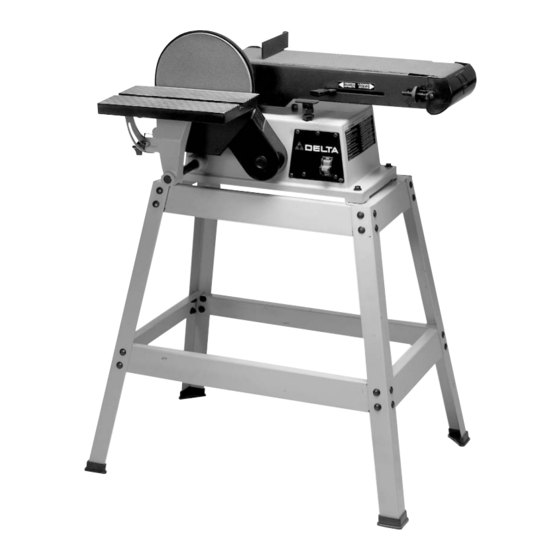
FUNCTIONAL DESCRIPTION FOREWORD The Delta Model 31-695 features a large 9" diameter abrasive disc out sharp corners. The Delta Model 31-695 also features an adjustable 6" belt unit horizontally or at any angle in between. UNPACKING AND CLEANING Carefully unpack the machine and all loose items from the shipping container(s). Remove the protective coating from all unpainted surfaces. - Page 7 Sander with 6" x 48" Sanding Belt and Backstop Sanding Disc Plate Belt and Pulley Cover 9" Sanding Disc Plug T-Wrench Drive Belt M6 x 55mm Hex Socket Head Screws (2) M6.4 Flat Washer (2 M6.4 Lockwasher (2) Disc Cover M4.2 x 13mm Panhead...
- Page 8 Carefully set the sander on the stand. Align the four holes on the top of stand (A) Fig. 5 with the four mounting holes on the base of sander (B). Place a 3/8" flat washer on an M8 x 45mm hex head screw (C). Insert the screw through the hole in the base of the machine (B) and stand (A).
-
Page 9: Sanding Disc Plate
BELT AND PULLEY GUARD Place an M6.4 lockwasher and an M6.4 flat washer in that order on two M6 x 55mm hex socket head screws (B), and attach the belt and pulley guard (A) Fig. 8 to the machine. NOTE: Install the plug (C) in the guard. SANDING DISC PLATE 1. -
Page 10: Starting And Stopping Sander
OPERATING CONTROLS AND ADJUSTMENTS STARTING AND STOPPING SANDER The switch (A) Fig. 16 is located on the sander base. To turn the sander “ON”, move the switch to the up position. To turn the sander “OFF”, move the switch to the down position. -
Page 11: Locking Switch In The "Off" Position
This can be done by grasping the switch toggle (B) and pulling it out of the switch, as shown in Fig. 20. With the switch toggle (B) removed, the switch will not operate. However, should the switch toggle be removed while the sander is running, it can be turned “OFF”... -
Page 12: Tilting The Table
2. Place a level (A) on the sanding belt. 3. To adjust, loosen the lock nut (B) Fig. 21, and turn the sanding arm stop (C) in or out until the sanding arm is level. After adjustment, tighten the lock nut (B). -
Page 13: Sanding Disc
SQUARING TABLE WITH SANDING DISC DISCONNECT MACHINE FROM POWER SOURCE. 1. Place one end of a combination square (C) Fig. 25 on the table with the other end against the sanding disc. 2. If the table surface is not 90 degrees to the disc, loosen the table lock knob (A) Fig. - Page 14 DUST SPOUT A dust spout (A) Fig. 32 is supplied with your sander and can easily be connected to a standard shop vacuum hose. The inside diameter opening of the dust spout (A) is 2-1/4".
-
Page 15: Wrench Storage
(A) Fig. 34 outward. WRENCH STORAGE A hole is provided in the stand for storing the hex wrench (A) Fig. 35, supplied with the sander. REMOVING UPPER SANDING DRUM GUARD You can remove the upper sanding drum guard (A) Fig. -
Page 16: Replacing Sanding Disc
“TIGHTEN” position. 7. Replace the support bracket, backstop and upper sanding drum guard, removed in STEPS 1 and 2. 8. Connect the electrical power to the sander. If the belt is not tracking properly, refer to section “TRACKING THE SANDING BELT.”... -
Page 17: Sanding Outside Curves
OPERATING CONTROLS AND ADJUSTMENTS Fig. 44 SURFACING OR EDGE SANDING WITH SANDING BELT When surfacing (Fig. 44) or edge sanding (Fig. 45), place the sanding arm in the horizontal position and use the backstop (A) Fig. 44 and Fig. 45 to keep the workpiece in place. Hold the workpiece firmly and keep your fingers away from the sanding belt. - Page 18 Fig. 48 END SANDING WITH THE DISC When sanding the ends of narrow workpieces, use the sanding disc and the accessory miter gauge (Fig. 48). Move the work from the center to the left side of the sanding disc. Always sand on the left (downward) side of the sanding disc. Sanding on the right (upward) side of the sanding disc could cause the workpiece to fly up, which could be hazardous.
-
Page 19: Keep Machine Clean
KEEP MACHINE CLEAN Periodically blow out all air passages with dry compressed air. All plastic parts should be cleaned with a soft damp cloth. NEVER use solvents to clean plastic parts. They could possibly dissolve or otherwise damage the material. Wear ANSI Z87.1 safety glasses while using compressed air. -
Page 20: Parts, Service Or Warranty Assistance
Two Year Limited New Product Warranty Delta will repair or replace, at its expense and at its option, any new Delta machine, machine part, or machine accessory which in normal use has proven to be defective in workmanship or material, provided that the customer returns the product prepaid to a Delta factory service center or authorized service station with proof of purchase of the product within two years and provides Delta with reasonable opportunity to verify the alleged defect by inspection. - Page 21 Phone: (604) 420-0102 Fax: (604) 420-3522 The following are trademarks of PORTER-CABLE • DELTA (Las siguientes son marcas registradas de PORTER-CABLE • DELTA S.A.) (Les marques suivantes sont des marques de fabriquant de la PORTER-CABLE • DELTA): Auto-Set Contractor’s Saw II™, Delta ®...
Need help?
Do you have a question about the (Model 31-695) and is the answer not in the manual?
Questions and answers