Table of Contents
Advertisement
Quick Links
Advertisement
Table of Contents

Related Manuals for ALLEN & HEATH iDR10


Summary of Contents for ALLEN & HEATH iDR10
- Page 1 ALLEN&HEATH iDR10 iLive System DSP MixRack USER GUIDE Publication AP6525...
-
Page 2: Limited Two Year Warranty
Allen & Heath could void the compliance of the product and therefore the users authority to operate it. iDR10 User Guide AP6525 Issue 1. Copyright © 2008 Allen & Heath. All rights reserved Manufactured in the United Kingdom by Allen & Heath Limited Kernick Industrial Estate, Penryn, Cornwall, TR10 9LU, UK http://www.allen-heath.com... -
Page 3: Read Instructions
Refer servicing to qualified technical personnel only. Installation Install the equipment in accordance with the instructions printed in this User Guide. Use the equipment connections for their intended purpose only. iDR10 User Guide... -
Page 4: Important Mains Plug Wiring Instructions
Ensure that the cables are located such that they cannot be stood on or tripped over. Modules: Do not remove the modules from the unit while power is applied. iDR10 User Guide... - Page 5 Introduction This is the user guide for the Allen & Heath iDR10 ‘MixRack’. We recommend that you read this fully before starting. Included is information on installing, connecting and operating the unit. Whilst we believe the information in this guide to be reliable we do not assume responsibility for inaccuracies.
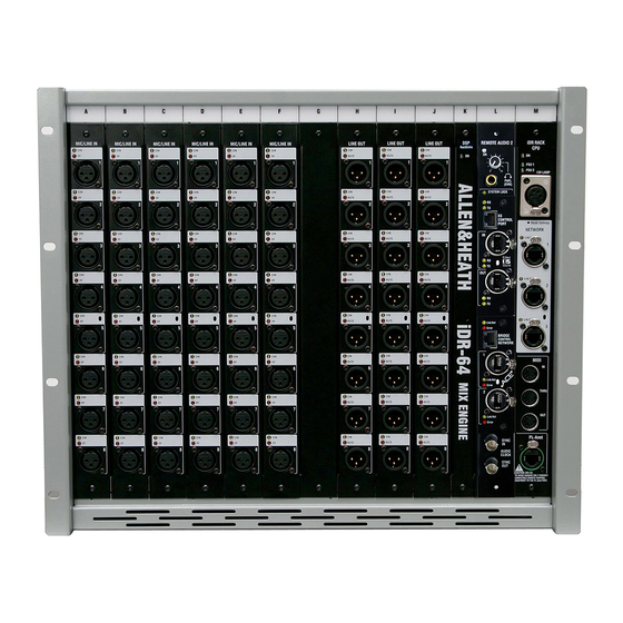
- Page 6 Welcome to the iDR10 MixRack The iDR10 is the heart of the iLive mixing system. It is called the ‘MixRack’ as it houses the iDR-64 DSP mix engine, the CPU module which manages and allows remote control of the mix functions, and the RAB (remote audio) module which provides up to two audio networking interfaces (currently both EtherSound).
-
Page 7: Flight Case
Note: Do not remove or plug POWER SUPPLY module in modules while power is Universal mains input. applied. The iLive system is not required. Fit second as redundant ‘hot pluggable’. supply backup. iDR10 User Guide... -
Page 8: Installation
Rack mounting The iDR10 is designed as a 19 inch rack mount unit and will occupy 9U of rack space. Ensure natural convection of airflow around the unit by allowing good ventilation below, in front of and behind the unit. -
Page 9: Connecting The System
Connecting the system The iDR10 requires two main system connections, both using CAT5 cables. NETWORK connects a remote controller such as the iLive Surface or a laptop. ESA connects audio to and from external locations such as the Surface and EtherSound equipped break in/out boxes. The optional ESB port can be used to connect audio between systems such as FOH/Monitor, broadcast or recording. -
Page 10: Power Up The System
Note: Read and understand the warnings in the safety sheet supplied with the iDR10 and printed on the power unit panel. Note: It is good practice to connect both the MixRack and... -
Page 11: Mic/Line Input
Lights when the socket is associated with a channel currently being PAFL’d, whether an output or insert send. MUTE A red LED lights when the output is muted. Note: The line outputs are relay switched to protect speaker systems from power on/off thumps. iDR10 User Guide... - Page 12 CHK will light whether the socket is the main mix output or an insert send. For example, three may be lit if you PAFL a stereo mix which has an insert assigned. MUTE A red LED lights when an output is muted. iDR10 User Guide...
- Page 13 PAFL’d at the surface or PC. This provides a quick way to check the socket patching, for example to identify which signals are feeding each channel of a personal monitoring system. MUTE A red LED lights when the output is muted. iDR10 User Guide...
-
Page 14: System Lock
Audio Clock Source is selected. Setting audio clock source (Surface TouchScreen MIXRACK / Mixer Pref / Audio Sync) If the iDR10 is part of a single rack system, or the master in a linked FOH/Monitor system then set the Clock Source to ‘Internal’. - Page 15 (Surface TouchScreen MIXRACK / Mixer Pref / Audio Sync) This screen lets you configure the iDR10 to be the ESB master or slave. If you are using ESB to provide audio to another system then set it as MASTER. If you are receiving the channel audio from another system then set it as MASTER/SLAVE.
-
Page 16: Cpu Module
NETWORK A 3 port Ethernet switch is built in. This lets you connect several network devices to the iDR10, for example an iLive Surface and a laptop running the iLive application software. The yellow Lnk/Act indicators flash to indicate network data activity. - Page 17 Using the iDR10 There are several ways the iDR10 can be used within an iLive system. It is one of many component options that may be configured to satisfy a host of demanding audio mixing applications. We recommend that you visit the Allen & Heath web site for information on the full range of iLive components available.
- Page 18 MAIN = LR I5-8 = MAIN1-4 I1-8 = ST AUX5-8 8x MTX = 4m 2st J1-4 = MTX1-4 J1-4 = MTX1-4 J5-6 = ST MTX1-2 J5-6 = ST MTX1 J7-8 = PAFL OUT MIC SPLITTER MONITOR SPLIT FOH SPLIT iDR10 User Guide...
- Page 19 I1-8 = ST AUX5-8 MAIN = LR MONITOR INPUTS J1-4 = MTX1-4 J1-4 = MTX1-4 8x MTX = 4m 2st A-F = BLANK J5-6 = ST MTX1 J5-6 = ST MTX1-2 CH1-56 = ESB J7-8 = PAFL OUT iDR10 User Guide...
- Page 20 18x AUX = 8m 1st 8FX I5-8 = MAIN1-4 I1-8 = ST AUX5-8 MAIN = LR J1-4 = MTX1-4 8x MTX = 4m 2st J1-4 = MTX1-4 J5-6 = ST MTX1 J5-6 = ST MTX1-2 J7-8 = PAFL OUT iDR10 User Guide...
- Page 21 AUDIO CLOCK = INTERNAL I3-4 = - ESB CONFIG = MASTER I5-8 = MAIN1-4 CH SOURCE = LOCAL INPUTS J1-4 = MTX1-4 J5-8 = ST MTX1-2 Set options using TOUCHSCREEN = MIXRACK / Mixer Pref / Audio Sync Networks iDR10 User Guide...
- Page 22 MIC SPLITTER (MIXRACK I/P 1-56) > ESB OUT AUDIO CLOCK = INTERNAL ESB CONFIG = MASTER CH SOURCE = LOCAL INPUTS STAGE INPUTS A1-G8 = I/P 1-56 CONFIG 26x AUX = 8m 2st 2FX 8x MTX = 4m 2st iDR10 User Guide...
- Page 23 G1-8 = AUX1-8 TB uses INPUT 48 H1-8 = ST AUX1-4 CONFIG I1-8 = ST AUX5-8 26x AUX = 8m 2st 2FX J1-4 = MTX1-4 8x MTX = 4m 2st J5-6 = ST MTX1 J7-8 = PAFL OUT iDR10 User Guide...
- Page 24 User Guide...
Need help?
Do you have a question about the iDR10 and is the answer not in the manual?
Questions and answers