
Related Manuals for Daewoo KOC-1B0K0S


Summary of Contents for Daewoo KOC-1B0K0S
-
Page 1: Microwave Oven
S/M No. : C1B0K0S003 Service Manual Microwave Oven Model : KOC-1B0K0S DAEWOO ELECTRONICS CO., LTD. http : //svc.dwe.co.kr Apr. 2001... -
Page 2: Table Of Contents
PRECAUTIONS TO BE OBSERVED BEFORE AND DURING SERVICING TO AVOID POSSIBLE EXPOSURE TO EXCESSIVE MICROWAVE ENERGY (a) Do not operate or allow the oven to be operated with the door open. (b) Make the following safety checks on all ovens to be serviced before activating the magnetron or other microwave source, and make repairs as necessary: (1) Interlock operation, (2) Proper door closing, (3) Seal and sealing surfaces (arcing, wear, and other damage), (4) Damage to or loosening of hinges and latches, (5) Evidence of dropping or abuse. -
Page 3: Safety And Precautions
1. SAFETY AND PRECAUTIONS 1. For Safe Operation Damage that allows the microwave energy (that cooks or heats the food) to escape will result in poor cooking and may cause serious bodily injury to the operator. IF ANY OF THE FOLLOWING CONDITIONS EXIST, OPERATOR MUST NOT USE THE APPLIANCE. -
Page 4: Specifications
2. SPECIFICATIONS MODEL KOC-1B0K POWER SUPPLY 230V~50Hz, SINGLE PHASE WITH EARTHING MICROWAVE 1500W POWER GRILL 1600W CONSUMPTION CONVECTION 2300W COMBINATION 3100W MICROWAVE ENERGY OUTPUT 1000W (IEC705) MICROWAVE FREQUENCY 2450MHz OUTSIDE DIMENSIONS (W X H X D) 560 x 344 x 542 mm (22.0 x 13.5 x 21.3 in.) CAVITY DIMENSIONS (W X H X D) 368.5 x 246 x 376.5 mm (14.5 x 9.7 x 14.8 in.) NET WEIGHT... -
Page 5: Feature Diagram
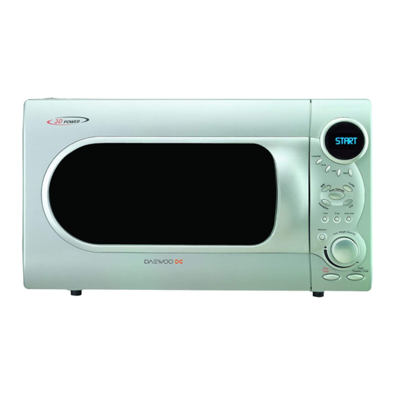
3-2. FEATURE DIAGRAM 1. Door hook – When the door is closed, it will automatically shut. If the door is opened while the oven is operating, the magnetron will immediately stop operating. 2. Door viewing screen – Allows viewing of food. The screen is designed so that light can pass through, but not the microwave. -
Page 6: Installation
• This appliance is supplied with cable of special type, which, if damaged, must be repaired with cable of same type. Such a cable can be purchased from DAEWOO and must be installed by a Qualified Person. -
Page 7: Control Panel
5. CONTROL PANEL DISPLAY WINDOW 1. MICROWAVE indicator, showing microwaving in progress 2. DEFROST indicator, showing defrosting in progress. 3. GRILL (upper grill heater) indicator showing grilling in progress. 4. GRILL (lower grill heater) indicator, showing grilling in progress. 5. CONVECTION indicator, showing convectioning in progress. -
Page 8: Disassembly And Assembly
6. DISASSEMBLY AND ASSEMBLY - Cautions to be observed when trouble shooting. Unlike many other appliances, the microwave oven is high-voltage, high-current equipment. It is completely safety during normal operation. However, carelessness in servicing the oven can result in an electric shock or possible danger from a short circuit. You are asked to observe the following precautions carefully. - Page 9 REMARK 3512204700 FRAME DOOR 3517006900 BARRIER-SCREEN*O TEMP GLASS T3.2 7112401011 SCREW TAPPING T1 TRS 4x10 MFZN 3515204900 STOPPER HINGE *T AS KOC-1B0K0S 3512302300 GASKET DOOR 7122401211 SCREW TAPPING T2S TRS 4x12 MFZN 3513101200 HOOK 3515101800 SPRING HOOK 3511714100 DOOR SEAL AS...
- Page 10 (1) Remove the gasket door from door plate. (2) Remove a screw from door plate. (3) Remove the door frame from door plate. (4) Remove the stopper hinge top from door plate. (5) Remove the spring and the hook. (6) Remove two screws from door frame. (7) Remove the handle door and barrier screen outer from door frame.
- Page 11 BUTTON FUNCTION-C ABS SG-175 SG-0760D 3516908400 BUTTON FUNCTION-B ABS SG-175 SG-0760D 7122401211 SCREW TAPPING T2S TRS 4X12 MFZN 3514323010 PCB MAIN AS KOC-1B0K0S 7121301011 SCREW TAPPING TS2 PAN 3X10 MFZN 3514323110 PCB SUB AS KOC-1B0K0S 3516908600 BUTTON FUNCTION-D ABS SG-175 SG-0760D...
- Page 12 6. To remove high voltage capacitor. (1) Remove a screw which secure the groun- ding ring terminal of the H.V.diode and the capacitor holder. (2) Remove the H.V. diode from the capacitor holder. (3) Reverse the above steps for reassembly. l High voltage circuit wiring 7.
- Page 13 8. To remove wind guide assembly. (1) Remove a screw for earthing. (2) Remove the noise filter from the wind guide. (3) Remove a screw which secure the wind guide assembly. (4) Draw forward the wind guide assembly. (5) Pull the fan from the motor shaft. (6) Remove two screws which secure the motor shaded pole.
- Page 14 T1 TRS 4X10 MFZN 3511407800 COVER LAMP STS430 T0.5 7112401011 SCREW TAPPING T1 TRS 4X10 MFZN 3513003900 HOLDER LAMP AS KOC-1B0K0S 3513602600 LAMP HALOGEN 3511407810 COVER LAMP GLASS T2.0 (1) Remove a screw and pull out Guideair outle (2) Remove two screws and pull out Insulator heater *t (3) Pull out the Lamp assembly.
- Page 15 GUIDE AIR OUTLET SA1D T0.5 3513302800 INSULATOR HEATER *T SBHG T0.6 7112401011 SCREW TAPPING T1 TRS 4X10 MFZN 3512767000 HARNESS HEATER KOC-1B0K0S 3510607700 BRACKET HEATER *T SA1D T0.5 3512803800 HEATER MIRACLON 115V 550W 270MM 3511407600 COVER HEATER *T STS430 T0.5 (1) Remove a screw and pull out Guide air outlet .
- Page 16 COVER MOTOR *B SBHG T0.6 7112401011 SCREW TAPPING T1 TRS 4X10 MFZN 3511407400 COVER *B SBHG T0.6 3512766900 HARNESS CONVECTION-B KOC-1B0K0S 3512803800 HEATER MIRACLON 115V 550W 270MM 3511407700 COVER HEATER *B SA1D T0.5 7113400814 SCREW TAPPING T1 BIN 4X8 MFNI...
- Page 17 13. To remove Motor synchro. And Under heater assembly parts. CUTTING (6EA) REF.NO PART CODE PART NAME DESCRIPTION Q’TY REMARK 7112401011 SCREW TAPPING T1 TRS 4X10 MFZN 3511407500 COVER HEATER *U STS430 T0.5 3515304000 SUPPORTER HEATER *U STS430 T0.5 3512802000 HEATER *U 230V 400W R18374001 7113400814...
-
Page 18: Interlock Mechanism And Adjustment
7. INTERLOCK MECHANISM AND ADJUSTMENT The door lock mechanism is a device which has been specially designed to completely eliminate microwave radiation when the door is opened during operation, and thus to perfectly prevent the danger resulting from the leakage of microwave. (1) Primary interlock switch When the door is closed, the hook locks the oven door. -
Page 19: Trouble Shooting Guide
8. TROUBLE SHOOTING GUIDE Following the procedure below to check if the oven is defective or not. 1) Check grounding before trouble checking. 2) Be careful of the high voltage circuit. 3) Discharge the high voltage capacitor. 4) When checking the continuity of the switches, fuse or high voltage tranformer, disconnect one load wire from these parts and check continuity with the AC plug removed. - Page 20 CONDITION CHECK RESULT CAUSE REMEDY Defective Outlet has Check continuity of Replace continuity magnetron. proper magnetron voltage fuse does not blow? Defective line Check continuity of noise filter Replace continuity board filter board Open power Check continuity of Replace continuity supply cord power supply cord Defective touch...
- Page 21 TROUBLE 3) No microwave oscillation even though fan motor rotates. CONDITION CHECK RESULT CAUSE REMEDY Check continuity of continuity high voltage fuse microwave oscillation Replace high voltage fuse Continuity Replace Check continuity of Defective high voltage capacitor terminals high voltage with wires removed transformer Continuity...
- Page 22 (TROUBLE 4) Grill heater (upper heater) is not heated; food will not become hot. CONDITION CHECK RESULT CAUSE REMEDY Malfunction of Adjust or Check continuity of Grill heater is primary Interlock replace continuity primary interlock switch not heated. switch Adjust or Malfunction of Check continuity of replace...
- Page 23 (TROUBLE 6) Lower heater is not heated; food will not become hot. CONDITION CHECK RESULT CAUSE REMEDY Malfunction of Adjust or Check continuity of Lower heater primary Interlock Replace continuity Primary interlock switch Is not heated switch Adjust or Check continuity of Malfunction of replace secondary interlock...
- Page 24 (TROUBLE 8) When “ERROR 2 ERROR 3” come on display. CAUSE CONDITION CHECK RESULT REMEDY “ERROR 2 & 0Ω or infinite Replace Replace Check continuity of thermistor ERROR 3” (resistance of thermistor) come on display Approx 200k~300kΩ (room temperature) Defective Replace Check continuity of heater continuty...
-
Page 25: Measurement And Test
9. MEASUREMENT AND TEST 9-1. MEASUREMENT OF THE MICROWAVE POWER OUTPUT Microwave output power can be checked by indirectly measuring the temperature rise of a certain amount of water exposed to the microwave as directed below. PROCEDURE Microwave power output measurement is made wit the microwave oven supplied at rated voltage and operated at its maximum microwave power setting with a load of 1000 ±... -
Page 26: Microwave Radiation Test
9-2. MICROWAVE RADIATION TEST WARNING Make sure to check the microwave leakage before and after repair of adjustment. Always start measuring of an unknown field to assure safety for operating personnel from microwave energy. Do not place your hands into any suspected microwave radiation field unless the safe density level is known. -
Page 27: Component Test Procedure
9-3. COMPONENT TEST PROCEDURE • High voltage is present at the high voltage terminal of the high voltage transformer during any cooking cycle. • It is neither necessary nor advisable to attempt measurement of the high voltage. • Before touching any oven components or wiring, always unplug the oven from its power source and discharge the capacitor. -
Page 28: Component Action
9-4. COMPONENT ACTION MAGNE- UPPER LOWER REAR CONVEC- COOKING MODE TRON ELEMENT ELEMENT ELEMENT TION FAN GRILL-1 GRILL-2 GRILL-3 COMBI-1 COMBI-2 MANUAL MODE COMBI-3 COMBI-4 COMBI-5 CONVECTION 100~130 ¡ É CONVECTION 140~150 ¡ É CONVECTION 160~250 ¡ É CAKE / BREAD TOUCH CRUSTY ROAST BEEF... -
Page 29: Wiring Diagram
10. WIRING DIAGRAM... -
Page 30: Exploded View And Parts List
11. EXPLODED VIEW AND PARTS LIST 11-1. DOOR ASSEMBLY Refer to 6.Disassembly and assembly. 11-2. CONTROL PANEL ASSEMBLY Refer to 6.Disassembly and assembly. 11-3. TOTAL ASSEMBLY... - Page 31 PART CORD PART NAME DESCRIPTION Q'TY 3511714000 DOOR AS KOC-1B0K0S 3516724900 CONTROL PANEL AS KOC-1B0K0S 3515202200 STOPPER HINGE *U AS KOR-121M0A 7122400800 SCREW TAPTITE TT3 TRS 4X8 MFZN 3510313500 BASE SBHG T0.8 7112401011 SCREW TAPPING T1 TRS 4X10 MFZN 3512101400...
- Page 32 PART CORD PART NAME DESCRIPTION Q'TY 3512766800 HARNESS CONVECTION-A KOC-1B0K0S 3511407700 COVER HEATER *B SA1D T0.5 3513302900 INSULATOR HEATER *B SA1D T0.5 7113400814 SCREW TAPPING T1 BIN 4X8 MFNI 3963514300 MOTOR SHADED POLE 230V 50Hz MW10CA-T02 3511800800 PP GF20 7601400811...
- Page 33 PART CORD PART NAME DESCRIPTION Q'TY 3514801400 SENSOR TEMPERATURE PTM-K312-D7 3512767000 HARNESS HEATER KOC-1B0K0S 3517207300 TRAY RACK AS KOC-1B0KOS 120MM 3517207310 TRAY RACK AS KOC-1B0KOS 30MM 3517207200 TRAY METAL SPP T0.6 3512521000 GUIDE ROLLER AS KOC-1B0K0S 3516003700 SPECIAL SCREW TT3 HEX 4X8 FLG MFZN...
-
Page 34: Printed Circuit Board
12. P R INT E D C IR C UIT B OAR D 1. C IR C UIT C HE C K P R OC E DUR E 1) Low voltage trans former check T he low voltage trans former is located on the P.C .B . Meas uring condition: Input voltage: 230 V / F requency: 50Hz Terminal V oltage(load) - Page 35 3) Case of no microwave oscillation (1) When touching M/W button, oven lamp turns on and Fan motor and turntable rotate, and cook indicator in display comes on. * Cause: RELAY 1 does not operate. - Check method STATE POINT A POINT B RELAY 1 ON +5V DC...
- Page 36 4) Case of no heating of upper grill When touching GRILL1 & COMBI button, oven lamp turns on and fan motor and turntable motor rotate and cook indicator in the display comes on. l Cause: RELAY 2 does not operate. STATE POINT A POINT B...
- Page 37 STATE POINT A POINT B RELAY 3 ON +5V DC RELAY 3 OFF +24V DC 7) Case of no stopping of the count do wn timer When the door is opened during operation, the count down timer does not stop. - Check method POINT STATE...
-
Page 38: Circuit Diagram
13. P.C.B. CIRCUIT DIAGRAM... - Page 39 PCB ASS ’Y PART LIST NAME SYMBOL SPECIFCATION PART CODE Q'TY PCB MAIN M223 95.5 X 197 3514322300 PCB SUB M224 90 X 197 3514322310 BUZZER BM-20K 3515600100 CAPACITOR CERAMIC C1~C3,C6~C11 104 50V Z AXIAL CCZF1H104Z CAPACITOR CERAMIC C4,C5 102 50V Z AXIAL CCZB1H102K CAPACITOR ELECTRO 50V RS 10uF...
Need help?
Do you have a question about the KOC-1B0K0S and is the answer not in the manual?
Questions and answers