Table of Contents
Advertisement
Quick Links
S/M No. : C1B0K0S004
Service Manual
Microwave Oven
Model: KOC-1B0K0S
KOC-1B2K0S
Caution
: In this Manual, some parts can be changed for improving,
their performance without notice in the parts list. So, if you
need the latest parts information, please refer to PPL(Parts
Price List) in Service Information Center (http://svc.dwe.co.kr).
Aug. 2008
Advertisement
Table of Contents

Subscribe to Our Youtube Channel
Related Manuals for Daewoo KOC-1B0K0S


Summary of Contents for Daewoo KOC-1B0K0S
- Page 1 S/M No. : C1B0K0S004 Service Manual Microwave Oven Model: KOC-1B0K0S KOC-1B2K0S Caution : In this Manual, some parts can be changed for improving, their performance without notice in the parts list. So, if you need the latest parts information, please refer to PPL(Parts Price List) in Service Information Center (http://svc.dwe.co.kr).
-
Page 2: Table Of Contents
PRECAUTIONS TO BE OBSERVED BEFORE AND DURING SERVICING TO AVOID POSSIBLE EXPOSURE TO EXCESSIVE MICROWAVE ENERGY (a) Do not operate or allow the oven to be operated with the door open. (b) Make the following safety checks on all ovens to be serviced before activating the magnetron or other microwave source, and make repairs as necessary: (1) Interlock operation, (2) Proper door closing, (3) Seal and sealing surfaces (arcing, wear, and other damage), (4) Damage to or loosening of hinges and latches, (5) Evidence of dropping or abuse. -
Page 3: Safety And Precautions
1. SAFETY AND PRECAUTIONS 1. FOR SAFE OPERATION Damage that allows the microwave energy (that cooks or heats the food) to escape will result in poor cooking and may cause serious bodily injury to the operator. IF ANY OF THE FOLLOWING CONDITIONS EXIST, OPERATOR MUST NOT USE THE APPLIANCE. (Only a trained service personnel should make repairs.) 1) A broken door hinge. -
Page 4: Specifications
2. SPECIFICATIONS MODEL KOC-1B0K / KOC-1B2K POWER SUPPLY 230V~50Hz, SINGLE PHASE WITH EARTHING MICROWAVE 1500W POWER GRILL 1600W CONSUMPTION COMBECTION 2300W COMBINATION 3100W MICROWAVE ENERGY OUTPUT 1000W(IEC705) MICROWAVE FREQUENCY 2450MHz OUTSIDE DIMENSIONS (W X H X D) 560X344X542mm (22.0X13.5X21.3 in.) CAVITY DIMENSIONS (W X H X D) 368.5X246X376.5mm (14.5X9.7X14.8 in.) NET WEIGHT... -
Page 5: Feature Diagram
3-2. FEATURE DIAGRAM 11.DOOR HOOK When the door is closed, it will automatically shut. If the door is opened while the oven is operating, the magnetron will immediately stop operating. 12.DOOR VIEWING SCREEN Allows viewing of food. The screen is designed so that light can pass through, but not the microwave. 13.METAL RACK 14.TOP HEATER Turns on when convection, grill and combi cooking is selected. -
Page 6: Installation
• This appliance is supplied with cable of special type, which, if damaged, must be repaired with cable of same type. Such a cable can be purchased from DAEWOO and must be installed by a Qualified Person. 6. Examine the oven after unpacking for any damage such as: A misaligned door, broken door or a dent in cavity. -
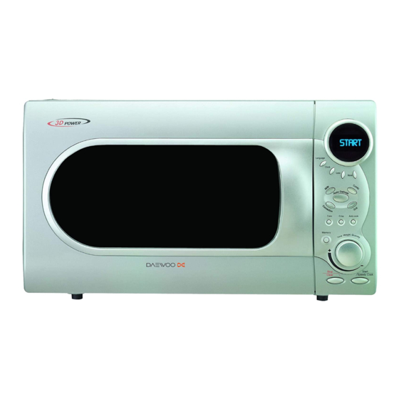
Page 7: Control Panel
18. cake : Press to select cake menu. 19. crusty : Press to select crusty menu. 20. auto cook : Press to select auto cook menu. 21. memory : Use to set favorite cooking mode.(KOC-1B0K0S/1B2K0S) barbecue : Press to select barbecue mode.(KOC-1B0K0S01/1B2K0S01) Stop/ Start/ 22. -
Page 8: Disassembly And Assembly
6. DISASSEMBLY AND ASSEMBLY - Cautions to be observed when trouble shooting. Unlike many other appliances, the microwave oven is high-voltage, high-current equipment. It is completely safety during normal operation. However, carelessness in servicing the oven can result in an electric shock or possible danger from a short circuit. - Page 9 1. To remove cabinet 1) Remove four screws on cabinet back. 2) Push the cabinet backward. 2. To remove door assembly 1) Remove two screws which secure the stopper hinge top. 2) Remove the door assembly from top plate of cavity. 3) Reverse the above for assembly.
- Page 10 3. To remove door parts. REF NO. PART CODE PART NAME DESCRIPTION Q’TY REMARK 3512204700 FRAME DOOR 3512204720 PC SPRAY KOC-1B0K0S only 3517006900 BARRIER-SCREEN*O TEMP GLASS T3.2 7112401011 SCREW TAPPING T1 TRS 4X10 MFZN 3515204900 STOPPER HINGE *T AS KOC-1B0K0S 3512302300...
- Page 11 4. Method to reduce the gap between the door seal and the oven front surface. (1) To reduce gap located on part ‘A’. • Loosen two screws on stopper hinge top, and then push the door to contact the door seal to oven front surface. •...
- Page 12 REF NO. PART CODE PART NAME DESCRIPTION Q’TY REMARK 3511605000 DECORATOR C-PANEL ABS XR-401 H-2938 3511605010 ABS XR-401 SPRAY KOC-1B0K0S only 3511605110 DECORATOR RING ABS SG-175 SG-0760D 3515501700 WINDOW DISPLAY PMMA 3516724100 CONTROL PANEL ABS XR-401 H-2938 3516724120 ABS XR-401 SPRAY...
- Page 13 6. To remove high voltage capacitor. (1) Remove a screw which secure the grounding ring terminal of the H.V.diode and the capacitor holder. (2) Remove the H.V. diode from the capacitor holder. (3) Reverse the above steps for reassembly. High voltage circuit wiring 7.
- Page 14 8. To remove wind guide assembly. (1) Remove a screw for earthing. (2) Remove the noise filter from the wind guide. (3) Remove a screw which secure the wind guide assembly. (4) Draw forward the wind guide assembly. (5) Pull the fan from the motor shaft. (6) Remove two screws which secure the motor shaded pole.
- Page 15 10. To remove Lamp assembly parts. REF NO. PART CODE PART NAME DESCRIPTION Q’TY REMARK 7112401011 SCREW TAPPING T1 TRS 4X10 MFZN 3512520500 GUIDE AIR OUTLET SA1D T0.5 3513302800 INSULATOR HEATER *T SBHG T0.6 7112401011 SCREW TAPPING T1 TRS 4X10 MFZN 3511407800 COVER LAMP STS430 T0.5...
- Page 16 GUIDE AIR OUTLET SA1D T0.5 3513302800 INSULATOR HEATER *T SBHG T0.6 7s432x4081 SPECIAL SCREW TT3 TRS 4*8 SE MFZN 3512767000 HARNESS HEATER KOC-1B0K0S 3510607700 BRACKET HEATER *T SA1D T0.5 3512803800 HEATER MIRACLON 115V 550W 270MM 3511407600 COVER HEATER *T STS430 T0.5...
- Page 17 COVER MOTOR *B SBHG T0.6 7S312X40A1 SCREW SPECIAL T1 TRS 4*10 SE MFZN 3511407400 COVER *B SBHG T0.6 3512766900 HARNESS CONVECTION-B KOC-1B0K0S 3512803800 HEATER MIRACLON 115V 550W 270MM 3511407700 COVER HEATER *B SA1D T0.5 7113400814 SCREW TAPPING T1 BIN 4X8 MFNI...
- Page 18 13. To remove Motor synchro. And Under heater assembly parts. CUTTING (6EA) REF NO. PART CODE PART NAME DESCRIPTION Q’TY REMARK 7S312X40A1 SCREW SPECIAL T1 TRS 4*10 SE MFZN 3511407500 COVER HEATER *U SA1D 3515304000 SUPPORTER HEATER *U STS430 T0.5 3512802000 HEATER *U 230V 400W R18374001...
-
Page 19: Interlock Mechanism And Adjustment
7. INTERLOCK MECHANISM AND ADJUSTMENT The door lock mechanism is a device which has been specially designed to completely eliminate microwave radiation when the door is opened during operation, and thus to perfectly prevent the danger resulting from the leakage of microwave. (1) Primary interlock switch When the door is closed, the hook locks the oven door. -
Page 20: Troubleshooting Guide
8. TROUBLESHOOTING GUIDE Following the procedure below to check if the oven is defective or not. 1) Check grounding before trouble checking. 2) Be careful of the high voltage circuit. 3) Discharge the high voltage capacitor. 4) When checking the continuity of the switches, fuse or high voltage tranformer, disconnect one load wire from these parts and check continuity with the AC plug removed. - Page 21 CONDITION CHECK RESULT CAUSE REMEDY Defective Outlet has Check continuity of Replace continuity magnetron. proper magnetron voltage fuse does not blow? Defective line Check continuity of noise filter Replace continuity filter board board Open power Check continuity of Replace continuity power supply cord supply cord Defective touch...
- Page 22 TROUBLE 3) No microwave oscillation even though fan motor rotates. CONDITION CHECK RESULT CAUSE REMEDY Check continuity of continuity high voltage fuse microwave oscillation Replace high voltage fuse Continuity Replace Check continuity of Defective high voltage capacitor terminals high voltage with wires removed transformer Continuity...
- Page 23 (TROUBLE 4) Grill heater (upper heater) is not heated; food will not become hot. CONDITION CHECK RESULT CAUSE REMEDY Malfunction of Adjust or Check continuity of Grill heater is primary Interlock replace continuity primary interlock switch not heated. switch Adjust or Malfunction of Check continuity of replace...
- Page 24 (TROUBLE 6) Lower heater is not heated; food will not become hot. CONDITION CHECK RESULT CAUSE REMEDY Malfunction of Adjust or Check continuity of Lower heater primary Interlock Replace continuity Is not heated Primary interlock switch switch Adjust or Check continuity of Malfunction of replace secondary interlock...
- Page 25 (TROUBLE 8) When “ERROR 2 ERROR 3” come on display. CAUSE CONDITION CHECK RESULT REMEDY “ERROR 2 & 0Ω or infinite Replace Replace Check continuity of thermistor ERROR 3” (resistance of thermistor) come on display Approx 200k~300kΩ (room temperature) Defective Replace Check continuity of heater continuty...
-
Page 26: Mesurement And Test
9. MEASUREMENT AND TEST 9-1. MEASUREMENT OF THE MICROWAVE POWER OUTPUT Microwave output power can be checked by indirectly measuring the temperature rise of a certain amount of water exposed to the microwave as directed below. PROCEDURE 1. Microwave power output measurement is made with the microwave oven supplied at rated voltage and operated at its maximum microwave power setting with a load of 1000 ±... -
Page 27: Microwave Radiation Test
9-2. MICROWAVE RADIATION TEST WARNING 1. Make sure to check the microwave leakage before and after repair of adjustment. 2. Always start measuring of an unknown field to assure safety for operating personnel from microwave energy. 3. Do not place your hands into any suspected microwave radiation field unless the safe density level is known. 4. -
Page 28: Component Test Procedure
9-3. COMPONENT TEST PROCEDURE • High voltage is present at the high voltage terminal of the high voltage transformer during any cooking cycle. • It is neither necessary nor advisable to attempt measurement of the high voltage. • Before touching any oven components or wiring, always unplug the oven from its power source and discharge the capacitor. -
Page 29: Component Action
9-4. COMPONENT ACTION MAGNE- UPPER LOWER REAR CONVEC- COOKING MODE TRON ELEMENT ELEMENT ELEMENT TION FAN GRILL-1 GRILL-2 GRILL-3 COMBI-1 COMBI-2 MANUAL COMBI-3 MODE COMBI-4 COMBI-5 CONVECTION100~130 CONVECTION140~150 CONVECTION160~250 CAKE/BREAD TOUCH CRUSTY ROAST BEEF ROAST CHICKEN ROAST PORK BAKED FISH AUTO BAKED POTATO MODE... -
Page 30: Wiring Diagram
10. WIRING DIAGRAM - KOC-1B0K0S/1B2K0S... -
Page 31: Exploded View And Parts List
11. EXPLODED VIEW AND PARTS LIST 11-1. DOOR ASSEMBLY Refer to 6. Disassembly and assembly. 11-2. CONTROL PANEL ASSEMBLY Refer to 6. Disassembly and assembly. 11-3. TOTAL ASSEMBLY... - Page 32 PART CORD PART NAME DESCRIPTION Q'TY REMARK 3511714000 DOOR AS KOC-1B0K0S KOC-1B0K0S 3511714020 KOC-1B2K0S KOC-1B2K0S PKCPSWLG00 CONTROL PANEL AS KOC-1B0K0S KOC-1B0K0S PKCPSWLG10 KOC-1B2K0S KOC-1B2K0S 3515202200 STOPPER HINGE *U AS KOR-121M0A 7122400800 SCREW TAPTITE TT3 TRS 4X8 MFZN 3510313530 BASE SBHG...
- Page 33 PART NAME DESCRIPTION Q'TY REMARK 7400104011 WASHER PLAIN PW-1-4-MFZN 7113400814 SCREW TAPPING T1 BIN 4X8 MFNI 3512766800 HARNESS CONVECTION-A KOC-1B0K0S 3511407700 COVER HEATER *B SA1D 3513302900 INSULATOR HEATER *B SA1D 7113400814 SCREW TAPPING T1 BIN 4X8 MFNI 3963514330 MOTOR SHADED POLE...
- Page 34 3512803800 HEATER MIRACLON 115V 550W 270MM 3510607700 BRACKET HEATER *T SA1D 3514801400 SENSOR TEMPERATURE PTM-K312-D7 3512767000 HARNESS HEATER KOC-1B0K0S 3517207300 TRAY RACK AS KOC-1B0KOS 120MM 3517207310 TRAY RACK AS KOC-1B0KOS 30MM 3517211100 TRAY METAL AS KOC-1B0K0S 3512521000 GUIDE ROLLER AS...
-
Page 35: Printed Circuit Board
12. PRINTED CIRCUIT BOARD CIRCUIT CHECK PROCEDURE 1. Low voltage transformer check The low voltage transformer is located on the P.C.B. Measuring condition: Input voltage: 230V / Frequency: 50Hz Terminal Voltage(load) Voltage(no load) AC 17.0 V AC 19.9 V AC 1.3 V AC 1.6 V 9-10 AC 1.3 V... - Page 36 3. Case of no microwave oscillation 1) When touching M/W button, oven lamp turns on and Fan motor and turntable rotate, and cook indicator in display comes on. *Cause: RELAY 1 does not operate. - Check method STATE POINT A POINT B RELAY 1 ON +5V DC...
- Page 37 4. Case of no heating of upper grill When touching GRILL1 & COMBI button, oven lamp turns on and Fan motor and turntable motor rotate and cook indicator in the display comes on. *Cause: RELAY 2 does not operate. STATE POINT A POINT B RELAY 2 ON...
- Page 38 7. Case of no stopping of the count down timer When the door is opened during operation, the count down timer does not stop. - Check method POINT STATE DOOR OPEN OPEN +5V DC DOOR CLOSED CLOSE CHECK NO METHOD REMEDY Check the stage(ON,OFF) of the door open Replace door open monitor swith.
-
Page 39: Circuit Diagram
13. P.C.B. CIRCUIT DIAGRAM... - Page 40 PCB ASS’Y PART LIST NAME SYMBOL SPECIFCATION PART CODE Q'TY PCB MAIN M223 95.5 X 197 3514322300 PCB SUB M224 90 X 197 3514322310 BUZZER BM-20K 3515600100 CAPACITOR CERAMIC C1~C3,C6~C11 104 50V Z AXIAL CCZF1H104Z CAPACITOR CERAMIC C4,C5 102 50V Z AXIAL CCZB1H102K CAPACITOR ELECTRO 50V RS 10uF...
- Page 41 DAEWOO ELECTRONICS CORP. 686, AHYEON-DONG MAPO-GU SEOUL, KOREA C.P.O. BOX 8003 SEOUL, KOREA TELEX: DWELEC K28177-8 CABLE: “DAEWOOELEC” S/M NO. : C1B0K0S004 PRINTED DATE: Aug. 2008...
- Page 42 ABOUT THIS MANUAL ABOUT THIS MANUAL...
Need help?
Do you have a question about the KOC-1B0K0S and is the answer not in the manual?
Questions and answers