Table of Contents
Advertisement
Quick Links
Advertisement
Table of Contents

Related Manuals for DFI CA100-D


Summary of Contents for DFI CA100-D
-
Page 1: System Board
CA100-D System Board User’s Manual 935-CA1001-000G A10940020... -
Page 2: Copyright
Copyright This publication contains information that is protected by copyright. No part of it may be reproduced in any form or by any means or used to make any transfor- mation/adaptation without the prior written permission from the copyright hold- ers. -
Page 3: Fcc And Doc Statement On Class B
FCC and DOC Statement on Class B This equipment has been tested and found to comply with the limits for a Class B digital device, pursuant to Part 15 of the FCC rules. These limits are designed to provide reasonable protection against harmful interference when the equipment is operated in a residential installation. -
Page 4: Table Of Contents
Introduction Table of Contents Copyright ................... 2 Trademarks ..................2 FCC and DOC Statement on Class B ..........3 About this Manual ................7 Warranty ..................7 Static Electricity Precautions ............. 8 Safety Measures ................. 8 About the Package ................9 Before Using the System Board ............ - Page 5 Introduction I/O Connectors ................38 CD-in Internal Audio Connector ..........38 S/PDIF-out Connector ............... 39 LVDS LCD Panel and LCD/Inverter Power Connector ..... 40 Digital I/O Connector ..............42 SATA (Serial ATA) Connectors ............ 43 IDE Connector ................. 44 Cooling Fan Connectors ............. 46 Chassis Instrusion Connector ............
- Page 6 Introduction Appendix A - Watchdog Sample Code ......... 108 Appendix B - System Error Message ..........110 Appendix C - Troubleshooting ............112...
-
Page 7: About This Manual
Introduction About this Manual An electronic file of this manual is included in the CD. To view the user’s manual in the CD, insert the CD into a CD-ROM drive. The autorun screen (Main Board Utility CD) will appear. Click “User’s Manual” on the main menu. Warranty 1. -
Page 8: Static Electricity Precautions
Introduction Static Electricity Precautions It is quite easy to inadvertently damage your PC, system board, components or devices even before installing them in your system unit. Static electrical dis- charge can damage computer components without causing any signs of physical damage. -
Page 9: About The Package
Introduction About the Package The system board package contains the following items. If any of these items are missing or damaged, please contact your dealer or sales representative for as- sistance. One system board One IDE cable One USB cable ... -
Page 10: Chapter 1 - Introduction
Introduction Chapter 1 - Introduction Specifications Processor • Intel Core 2 Penryn processor ® • Intel Celeron 575 processor ® ® • 1066/800/667MHz FSB • Intel 45nm transistor technology ® • Intel Trusted Execution Technology (Intel TXT) ® ® • Intel Virtualization Technology (Intel VT) DMA ® ® • Supports Data Bus Inversion (DBI) • Supports Message Signaled Interrupt (MSI) • Supports Intel architecture with Intel Wide Dynamic Execution... - Page 11 Introduction • JMicron JMB368 PCI Express to PATA host controller • Supports Native Mode operation • Supports PIO Modes 0, 1, 2, 3, 4 • Supports Multiword DMA Modes 0, 1, 2 • Supports Ultra DMA 33/66/100/133 • Supports ATA/ATAPI command • 1 mini-DIN-6 PS/2 mouse port Rear Panel I/O • 1 mini-DIN-6 PS/2 keyboard port Ports • 2 DB-9 serial ports • 1 DB-15 VGA port • 1 DVI-I port (DVI-D signal only) • 2 RJ45 LAN ports • 4 USB 2.0/1.1 ports • Mic-in, line-in and line out jacks • 2 connectors for 4 additional external USB 2.0/1.1 ports I/O Connectors • 1 LVDS LCD panel connector • 1 LCD/inverter power connector • 1 Digital I/O connector • 1 front audio connector for line-out and mic-in jacks • 1 CD-in internal audio connector • 1 S/PDIF connector • 4 Serial ATA connectors • 1 40-pin IDE connector • 1 20-pin ATX power connector • 1 front panel connector • 2 fan connectors • Award BIOS BIOS • 16Mbit SPI flash memory • Supports ACPI specification and OS Directed Power Manage- Energy Efficient ment Design • Supports ACPI STR (Suspend to RAM) function • Wake-On-Events include:...
-
Page 12: Features
Introduction Features Watchdog Timer The Watchdog Timer function allows your application to regularly “clear” the sys- tem at the set time interval. If the system hangs or fails to function, it will reset at the set time interval so that your system will continue to operate. DDR3 DDR3 delivers increased system bandwidth and improved performance. - Page 13 Introduction S/PDIF S/PDIF is a standard audio file transfer format that transfers digital audio sig- nals to a device without having to be converted first to an analog format. This prevents the quality of the audio signal from degrading whenever it is converted to analog.
- Page 14 Introduction Wake-On-PS/2 This function allows you to use the PS/2 keyboard or PS/2 mouse to power-on the system. Important: The 5V_standby power source of your power supply must support ≥720mA. Wake-On-USB This function allows you to use a USB keyboard or USB mouse to wake up a sys- tem from the S3 (STR - Suspend To RAM) state.
-
Page 15: Chapter 2 - Hardware Installation
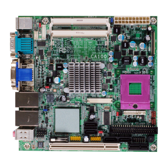
Hardware Installation Chapter 2 - Hardware Installation System Board Layout PS/2 power select ( DDR3_2 SODIMM Mouse ATX power Power-on select (J DDR3_1 SODIMM power Chassis COM 2 intrusion COM 1 Standby Power LED COM2 RS232/485 select ( Intel DVI-I G 45 USB 0-3 power select (... -
Page 16: System Memory
Hardware Installation Important: Electrostatic discharge (ESD) can damage your system board, processor, disk drives, add-in boards, and other components. Perform the upgrade instruction procedures described at an ESD workstation only. If such a station is not available, you can provide some ESD protection by wearing an antistatic wrist strap and attaching it to a metal part of the system chassis. -
Page 17: Installing The Dim Module
Hardware Installation Installing the SODIMM 1. Make sure the PC and all other peripheral devices connected to it has been powered down. 2. Disconnect all power cords and cables. 3. Locate the SODIMM socket on the board. 4. Note the key on the socket. The key ensures the module can be plugged into the socket in only one way. - Page 18 Hardware Installation 6. To seat the module into the socket, apply firm even pressure to each end of the module until it slips down into the socket. The contact fingers on the edge of the module will almost completely disappear inside the socket. Note: The board used in the following illustrations may not resemble the actual one.
-
Page 19: Cpu
Hardware Installation Overview The system board is equipped with a surface mount mPGA478 CPU socket. Note: The system board used in the following illustrations may not resemble the actual one. These illustrations are for reference only. Installing the CPU 1. Make sure the PC and all other peripheral devices connected to it has been powered down. - Page 20 Hardware Installation 5. Position the CPU above the socket. The gold triangular mark on the CPU must align with pin 1 of the CPU socket. Important: Handle the CPU by its edg- es and avoid touching the pins. Gold triangular mark Pin 1 6.
-
Page 21: Installing The Fan And Heat Sink
Hardware Installation Installing the Fan and Heat Sink The CPU must be kept cool by using a CPU fan with heat sink. Without sufficient air circulation across the CPU and heat sink, the CPU will overheat damaging both the CPU and system board. Note: •... - Page 22 Hardware Installation 4. Connect the CPU fan’s cable connector to the CPU CPU fan cable fan connector on the sys- tem board.
-
Page 23: Jumper Settings
Hardware Installation Jumper Settings Clear CMOS Data 1-2 On: Normal 2-3 On: (default) Clear CMOS Data If you encounter the following, a) CMOS data becomes corrupted. b) You forgot the supervisor or user password. you can reconfigure the system with the default values stored in the ROM BIOS. To load the default values stored in the ROM BIOS, please follow the steps below. -
Page 24: Ps/2 Power Select
Hardware Installation PS/2 Power Select 2-3 On: 1-2 On: 5V (default) 5V_standby JP1 is used to select the power of the PS/2 keyboard/mouse port. Selecting 5V_standby will allow you to use the PS/2 keyboard or PS/2 mouse to wake up the system. -
Page 25: Usb Power Select
Hardware Installation USB Power Select USB 0-3 (JP4) 1-2 On: 5V 2-3 On: 5V_standby (default) USB 4-7 (JP7) 2-3 On: 1-2 On: 5V (default) 5V_standby These jumpers are used to select the power of the USB ports. Selecting 5V_ standby will allow you to use a USB device to wake up the system. BIOS Setting “USB KB Wake-Up From S3”... -
Page 26: Com 2 Rs232/Rs485 Select
Hardware Installation COM 2 RS232/RS485 Select COM 2 JP5 is used to configure COM 2 to RS232 or RS485. The pin function of COM 2 will vary according to JP5’s setting. 5-6 On: RS485 1-2 On: RS232 (default) COM 2 1 2 3 4 5 1 2 3 4 5 6 7 8 9... -
Page 27: Power-On Select
Hardware Installation Power-on Select 1-2 On: 2-3 On: Power-on via Power-on via power button AC power (default) JP8 is used to select the method of powering on the system. If you want the system to power-on whenever AC power comes in, set JP8 pins 2 and 3 to On. If you want to use the power button, set pins 1 and 2 to On. -
Page 28: Panel Power Select
Hardware Installation Panel Power Select 1-4 On: 12V 2-5 On: 5V 3-6 On: 3.3V (default) JP9 is used to select the power supplied to the LCD panel. Important: Before powering-on the system, make sure JP9’s setting matches the LCD panel’s specification. Selecting the incorrect voltage will seriously damage the LCD panel. -
Page 29: Rear Panel I/O Ports
Hardware Installation Rear Panel I/O Ports PS/2 COM 2 LAN 1 LAN 2 Mouse Mic-in Line-in Line-out PS/2 COM 1 DVI-I USB 0-1 USB 2-3 (DVI-D signal only) The rear panel I/O ports consist of the following: • PS/2 mouse port • PS/2 keyboard port • 2 COM ports • VGA port • DVI-I port (DVI-D signal only) • 2 LAN ports •... -
Page 30: Ps/2 Mouse And Ps/2 Keyboard Ports
Hardware Installation PS/2 Mouse and PS/2 Keyboard Ports PS/2 Mouse PS/2 KB These ports are used to connect a PS/2 mouse and a PS/2 keyboard. The PS/2 mouse port uses IRQ12. If a mouse is not connected to this port, the system will reserve IRQ12 for other expansion cards. Important: Make sure to turn off your computer prior to connecting or disconnecting a mouse or keyboard. Failure to do so may damage the system board. Wake-On-PS/2 Keyboard/Mouse The Wake-On-PS/2 Keyboard/Mouse function allows you to use the PS/2 keyboard or PS/2 mouse to power-on the system. To use this function: • Jumper Setting JP1 must be set to “2-3 On: 5V_standby”. Refer to “PS/2 Power Select” in this chapter for more information. -
Page 31: Com (Serial) Ports
Hardware Installation COM (Serial) Ports COM 2 COM 1 1 2 3 4 5 COM 1 is fixed at RS232. 6 7 8 9 COM 2’s pin definition will vary according to JP5’s settings. Refer to “COM 2 RS232/RS485 Select” in this chapter for more information. The serial ports are asynchronous communication ports with 16C550A-compatible UARTs that can be used with modems, serial printers, remote display terminals, and other serial devices. -
Page 32: Vga Port
Hardware Installation VGA Port The VGA port is used for connecting a VGA monitor. Connect the monitor’s 15-pin D-shell cable connector to the VGA port. After you plug the monitor’s cable con- nector into the VGA port, gently tighten the cable screws to hold the connector in place. BIOS Setting Configure the onboard VGA in the Advanced Chipset Features submenu of the BIOS. Refer to chapter 3 for more information. -
Page 33: Dvi-I Port
Hardware Installation DVI-I Port DVI-I The DVI-I port is used to connect an LCD monitor. This port supports DVI-D sig- nal only. Connect the display device’s cable connector to the DVI-I port. After you plug the cable connector into the port, gently tighten the cable screws to hold the connec- tor in place. BIOS Setting Configure the display device in the Advanced Chipset Features submenu of the BIOS. Refer to chapter 3 for more information. -
Page 34: Rj45 Lan Port
Hardware Installation RJ45 LAN Ports LAN 1 LAN 2 The LAN ports allow the system board to connect to a local area network by means of a network hub. BIOS Setting Configure the onboard LAN ports in the Advanced Chipset Features submenu (“PCI Express Root Port Func” section) of the BIOS. Refer to chapter 3 for more information. -
Page 35: Usb Ports
Hardware Installation USB Ports USB 1 USB 0 USB 3 USB 6-7 USB 2 USB 4-5 USB allows data exchange between your computer and a wide range of simulta- neously accessible external Plug and Play peripherals. The system board is equipped with four onboard USB 2.0/1.1 ports. The two 10-pin connectors allow you to connect 4 additional USB 2.0/1.1 ports. The ad- ditional USB ports may be mounted on a card-edge bracket. Install the card-edge bracket to an available slot at the rear of the system chassis then insert the USB port cables to a connector. -
Page 36: Hardware Installation
Hardware Installation Wake-On-USB Keyboard/Mouse The Wake-On-USB Keyboard/Mouse function allows you to use a USB keyboard or USB mouse to wake up a system from the S3 (STR - Suspend To RAM) state. To use this function: • Jumper Setting JP4 and/or JP7 must be set to “2-3 On: 5V_standby”. Refer to “USB Power Select” in this chapter for more information. •... -
Page 37: Audio
Hardware Installation Audio Rear audio Mic-in Line-in Line-out Front audio Rear Audio The system board is equipped with 3 audio jacks. A jack is a one-hole connecting interface for inserting a plug. • Mic-in Jack (Pink) This jack is used to connect an external microphone. • Line-in Jack (Light Blue) This jack is used to connect any audio devices such as Hi-fi set, CD player, tape player, AM/FM radio tuner, synthesizer, etc. • Line-out Jack (Lime) This jack is used to connect a headphone or external speakers. Front Audio The front audio connector allows you to connect to the second line-out and mic- in jacks that are at the front panel of your system. -
Page 38: I/O Connectors
Hardware Installation I/O Connectors CD-in Internal Audio Connector Ground Ground Right audio Left audio channel channel The CD-in connector is used to receive audio from a CD-ROM drive, TV tuner or MPEG card. -
Page 39: S/Pdif-Out Connector
Hardware Installation S/PDIF Connector SPDIF out Ground SPDIF in The S/PDIF connector is used to connect an external S/PDIF port. Your S/PDIF port may be mounted on a card-edge bracket. Install the card-edge bracket to an available slot at the rear of the system chassis then connect the audio cable to the S/PDIF connector. Make sure pin 1 of the audio cable is aligned with pin 1 of the S/PDIF connector. -
Page 40: Lvds Lcd Panel And Lcd/Inverter Power Connector
Hardware Installation LVDS LCD Panel Connector LCD/Inverter Power Connector LVDS LCD panel LCD/Inverter power The system board allows you to connect a LCD Display Panel by means of the LVDS LCD panel connector and the LCD/Inverter power connector. These connec- tors transmit video signals and power from the system board to the LCD Display Panel. - Page 41 Hardware Installation LVDS LCD Panel Connector Pins Pins Function Function LVDS_Out3+ LVDS_Out7+ LVDS_Out3- LVDS_Out7- LVDS_Out2+ LVDS_Out6+ LVDS_Out2- LVDS_Out6- LVDS_Out1+ LVDS_Out5+ LVDS_Out1- LVDS_Out5- LVDS_Out0+ LVDS_Out4+ LVDS_Out0- LVDS_Out4- LVDS_CLK1+ LVDS_CLK2+ LVDS_CLK1- LVDS_CLK2- LVDS_DDCCLK N. C. LVDS_DDCDAA N. C. Panel Power Panel Power Panel Power Panel Power LCD/Inverter Power Connector...
-
Page 42: Digital I/O Connector
Hardware Installation Digital I/O Connector 5VSB Ground +12V DIO power The Digital I/O connector provides powering-on function to an external device that is connected to this connector. Digital I/O Connector Pins Function DIO0 DIO1 DIO2 DIO3 DIO4 DIO5 DIO6 DIO7... -
Page 43: Sata (Serial Ata) Connectors
Hardware Installation SATA (Serial ATA) Connectors SATA 0 SATA 3 SATA 2 SATA 1 The Serial ATA connectors are used to connect Serial ATA devices. Connect one end of the Serial ATA cable to a SATA connector and the other end to your Serial ATA device. BIOS Setting Configure the Serial ATA drives in the Integrated Peripherals submenu (“OnChip IDE Device” section) of the BIOS. Refer to chapter 3 for more information. -
Page 44: Ide Connector
Hardware Installation IDE Connector The IDE connector is used to connect hard drives. The connector on the IDE cable can be inserted into this connector only if pin 1 of the cable is aligned with pin 1 of this connector. The IDE connector supports 2 devices, a Master and a Slave. Use an IDE ribbon cable to connect the drives to the system board. An IDE ribbon cable have 3 connectors on them, one that plugs into the IDE connector on the system board and the other 2 connects to IDE devices. The connector at the end of the cable is for the Master drive and the connector in the middle of the cable is for the Slave... - Page 45 Hardware Installation Important: If you encountered problems while using an ATAPI CD-ROM drive that is set in Master mode, please set the CD-ROM drive to Slave mode. Some ATAPI CD-ROMs may not be recognized and cannot be used if incorrectly set in Master mode. BIOS Setting Configure the onboard IDE in the Integrated Peripherals submenu (“OnChip IDE Device” section) of the BIOS. Refer to chapter 3 for more information.
-
Page 46: Cooling Fan Connectors
Hardware Installation Cooling Fan Connectors Ground Power Sense CPU fan Ground Power Sense System fan The fan connectors are used to connect cooling fans. The cooling fans will provide adequate airflow throughout the chassis to prevent overheating the CPU and sys- tem board components. BIOS Setting The PC Health Status submenu of the BIOS will display the current speed of the cooling fans. Refer to chapter 3 for more information. -
Page 47: Chassis Instrusion Connector
Hardware Installation Chassis Instrusion Connector Ground Chassis signal The board supports the chassis intrusion detection function. Connect the chas- sis intrusion sensor cable from the chassis to this connector. When the system’s power is on and a chassis intrusion occurred, an alarm will sound. When the system’s power is off and a chassis intrusion occurred, the alarm will sound only when the system restarts. -
Page 48: Power Connectors
Hardware Installation Power Connectors Use a power supply that complies with the ATX12V Power Supply Design Guide Version 1.1. An ATX12V power supply unit has a standard 20-pin ATX main power connector that must be inserted into the board’s 20-pin connector. The power connector from the power supply unit is designed to fit the 20-pin connector in only one orientation. Make sure to find the proper orientation before plugging the connector. The system board requires a minimum of 300 Watt power supply to operate. Your system configuration (CPU power, amount of memory, add-in cards, peripherals, etc.) may exceed the minimum power requirement. To ensure that adequate power is provided, we strongly recommend that you use a minimum of 400 Watt (or greater) power supply. -
Page 49: Standby Power Led
Hardware Installation Standby Power LED Standby Power LED This LED will light when the system’s standby power is on. -
Page 50: Front Panel Connectors
Hardware Installation Front Panel Connectors HDD-LED RESET-SW PWR-LED PWR-BTN HDD-LED - HDD LED This LED will light when the hard drive is being accessed. RESET SW - Reset Switch This switch allows you to reboot without having to power off the system. PWR-BTN - Power Switch This switch is used to power on or off the system. PWR-LED - Power/Standby LED When the system’s power is on, this LED will light. When the system is in the S1 (POS - Power On Suspend) state, it will blink every second. When the system is in the S3 (STR - Suspend To RAM) state, it will blink every 4 seconds. -
Page 51: Expansion Slots
Hardware Installation Expansion Slots PCI Express x1 PCI Express x1 Slot Install PCI Express cards such as network cards or other cards that comply to the PCI Express specifications into the PCI Express x1 slot. PCI Slot The PCI slot supports expansion cards that comply with PCI specifications. -
Page 52: Battery
Hardware Installation Battery Battery The lithium ion battery powers the real-time clock and CMOS memory. It is an auxiliary source of power when the main power is shut off. Safety Measures • Danger of explosion if battery incorrectly replaced. • Replace only with the same or equivalent type recommend by the manufac- turer. • Dispose of used batteries according to local ordinance. -
Page 53: Chapter 3 - Bios Setup
BIOS Setup Chapter 3 - BIOS Setup Award BIOS Setup Utility The Basic Input/Output System (BIOS) is a program that takes care of the ba- sic level of communication between the processor and peripherals. In addition, the BIOS also contains codes for various advanced features found in this system board. -
Page 54: Standard Cmos Features
BIOS Setup Standard CMOS Features Use the arrow keys to highlight “Standard CMOS Features” and press <Enter>. A screen similar to the one below will appear. Phoenix - AwardBIOS CMOS Setup Utility Standard CMOS Features Thu, Jul 9 2009 Date <mm:dd:yy> Item Help Time <hh:mm:ss>... - Page 55 BIOS Setup IDE Channel 0 Master to IDE Channel 4 Slave To configure the IDE drives, move the cursor to a field then press <Enter>. The following screen will appear. Phoenix - AwardBIOS CMOS Setup Utility IDE Channel 0 Master Press Enter Item Help IDE HDD Auto-Detection...
- Page 56 BIOS Setup Head This field displays the number of read/write heads. Precomp This field displays the number of cylinders at which to change the write tim- ing. Landing Zone This field displays the number of cylinders specified as the landing zone for the read/write heads.
- Page 57 BIOS Setup Base Memory Displays the amount of base (or conventional) memory installed in the system. The value of the base memory is typically 512K for systems with 512K memory installed on the motherboard or 640K for systems with 640K or more memory installed on the motherboard.
-
Page 58: Advanced Bios Features
BIOS Setup Advanced BIOS Features The Advanced BIOS Features allows you to configure your system for basic op- eration. Some entries are defaults required by the system board, while others, if enabled, will improve the performance of your system or let you set some fea- tures according to your preference. -
Page 59: Execute Disable Bit
BIOS Setup CPU Feature This field is used to configure the CPU that is installed on the system board. Move the cursor to this field then press <Enter>. Phoenix - AwardBIOS CMOS Setup Utility CPU Feature C1E Function Item Help Auto Execute Disable Bit Enabled... -
Page 60: Hard Disk Boot Priority
BIOS Setup Hard Disk Boot Priority This field is used to select the boot sequence of the hard drives. Move the cursor to this field then press <Enter>. Use the Up or Down arrow keys to select a de- vice then press <+> to move it up or <-> to move it down the list. Phoenix - AwardBIOS CMOS Setup Utility Hard Disk Boot Priority 1. - Page 61 BIOS Setup APIC Mode Leave this field in its default setting. HDD S.M.A.R.T. Capability The system board supports SMART (Self-Monitoring, Analysis and Reporting Technology) hard drives. SMART is a reliability prediction technology for ATA/IDE and SCSI drives. The drive will provide sufficient notice to the system or user to backup data prior to the drive’s failure.
-
Page 62: Advanced Chipset Features
BIOS Setup Advanced Chipset Features Phoenix - AwardBIOS CMOS Setup Utility Advanced Chipset Features Enabled System BIOS Cacheable Item Help Memory Hole At 15M-16M Disabled Menu Level Disabled Support FSB and DDR3 667Mhz PCI Express Root Port Func Press Enter ... - Page 63 BIOS Setup PCI Express Root Port Func Phoenix - AwardBIOS CMOS Setup Utility PCI Express Root Port Func PCI Express GLAN1 Port Auto Item Help PCI Express GLAN2 Port Auto Menu Level PCI Express IDE Port Auto PCI Express Slot Port Auto PCI-E Compliancy Mode v1.0a...
- Page 64 BIOS Setup DVMT Mode This field is used to configure the DVMT mode. Total GFX Memory For Windows XP operating system, the maximum value is based on the system memory size. 512MB for 1GB DRAM 768MB for 1.5GB to 2GB DRAM 1GB for above 2GB DRAM The options are 128MB, 256MB and MAX.
-
Page 65: Integrated Peripherals
BIOS Setup Integrated Peripherals Phoenix - AwardBIOS CMOS Setup Utility Integrated Peripherals Press Enter Item Help OnChip IDE Device Press Enter Super IO Device Menu Level Press Enter USB Device Setting : Move Enter: Select +/-/PU/PD: Value F10: Save ESC: Exit F1: General Help... -
Page 66: Legacy Mode Support
BIOS Setup OnChip IDE Device Move the cursor to this field and press <Enter>. The following screen will appear. Phoenix - AwardBIOS CMOS Setup Utility OnChip IDE Device Item Help SATA Mode Disabled Legacy Mode Support Menu Level If your IDE hard drive supports block mode Select Enabled for automatic detection of... - Page 67 BIOS Setup Super IO Device Move the cursor to this field and press <Enter>. The following screen will appear. Phoenix - AwardBIOS CMOS Setup Utility Super IO Device Power On Function BUTTON ONLY Item Help Onboard Serial Port 1 3F8/IRQ4 Menu Level Onboard Serial Port 2 2F8/IRQ3...
- Page 68 BIOS Setup PWRON After PWR-Fail When power returns after an AC power failure, the system’s power is off. You must press the Power button to power-on the system. When power returns after an AC power failure, the system will automatically power-on.
- Page 69 BIOS Setup USB Device Setting Move the cursor to this field and press <Enter>. The following screen will ap- pear. Phoenix - AwardBIOS CMOS Setup Utility USB Device Setting USB 1.0 Controller Enabled Item Help Enabled USB 2.0 Controller Menu Level Disabled USB Keyboard Function ...
-
Page 70: Power Management Setup
BIOS Setup Power Management Setup The Power Management Setup allows you to configure your system to most ef- fectively save energy. Phoenix - AwardBIOS CMOS Setup Utility Power Management Setup Enabled ACPI Function Item Help ACPI Suspend Type S1(POS) Menu Level Instant-Off Soft-Off By PWR-BTTN ... - Page 71 BIOS Setup Wake-Up By PCI Card Enabled This field should be set to Enabled only if your PCI card such as LAN card or modem card uses the PCI PME (Power Management Event) signal to remotely wake up the system. Access to the LAN card or PCI card will cause the sys- tem to wake up.
-
Page 72: Pnp/Pci Configurations
BIOS Setup PnP/PCI Configurations This section shows how to configure the PCI bus system. It covers some very technical items and it is strongly recommended that only experienced users should make any changes to the default settings. Phoenix - AwardBIOS CMOS Setup Utility PnP/PCI Configurations Init Display First Onboard... -
Page 73: Irq Resources
BIOS Setup IRQ Resources Move the cursor to this field and press <Enter>. Set each system interrupt to either PCI Device or Reserved. Phoenix - AwardBIOS CMOS Setup Utility IRQ Resources IRQ-3 assigned to PCI Device Item Help PCI Device IRQ-4 assigned to Menu Level PCI Device... -
Page 74: Pc Health Status
BIOS Setup PC Health Status Phoenix - AwardBIOS CMOS Setup Utility PC Health Status Case Open Detection Disabled Item Help Current System Temp C/93 Menu Level Current CPU Temperature C/98 Current System Fan Speed Current CPU Fan Speed 4963 RPM Vcore 1.16V 12.13V... -
Page 75: Frequency/Voltage Control
BIOS Setup Frequency/Voltage Control Phoenix - AwardBIOS CMOS Setup Utility Frequency/Voltage Control Spread Spectrum Enabled Item Help Menu Level : Move Enter: Select +/-/PU/PD: Value F10: Save ESC: Exit F1: General Help ↑↓→← F5: Previous Values F6: Fail-Safe Defaults F7: Optimized Defaults The settings on the screen are for reference only. -
Page 76: Load Fail-Safe Defaults
BIOS Setup Load Fail-Safe Defaults The “Load Fail-Safe Defaults” option loads the troubleshooting default values per- manently stored in the ROM chips. These settings are not optimal and turn off all high performance features. You should use these values only if you have hard- ware problems. -
Page 77: Load Optimized Defaults
BIOS Setup Load Optimized Defaults The “Load Optimized Defaults” option loads optimized settings from the BIOS ROM. Use the default values as standard values for your system. Highlight this option in the main menu and press <Enter>. Phoenix - AwardBIOS CMOS Setup Utility Standard CMOS Features Frequency/Voltage Control ... -
Page 78: Set Supervisor Password
BIOS Setup Set Supervisor Password If you want to protect your system and setup from unauthorized entry, set a supervisor’s password with the “System” option selected in the Advanced BIOS Features. If you want to protect access to setup only, but not your system, set a supervisor’s password with the “Setup”... -
Page 79: Set User Password
BIOS Setup Set User Password If you want another user to have access only to your system but not to setup, set a user’s password with the “System” option selected in the Advanced BIOS Features. If you want a user to enter a password when trying to access setup, set a user’s password with the “Setup”... -
Page 80: Save & Exit Setup
BIOS Setup Save & Exit Setup When all the changes have been made, highlight “Save & Exit Setup” and press <Enter>. Phoenix - AwardBIOS CMOS Setup Utility Standard CMOS Features Frequency/Voltage Control Advanced BIOS Features Load Fail-Safe Defaults ... -
Page 81: Exit Without Saving
BIOS Setup Exit Without Saving When you do not want to save the changes you have made, highlight “Exit With- out Saving” and press <Enter>. Phoenix - AwardBIOS CMOS Setup Utility Standard CMOS Features Frequency/Voltage Control Advanced BIOS Features Load Fail-Safe Defaults ... -
Page 82: Updating The Bios
BIOS Setup Updating the BIOS To update the BIOS, you will need the new BIOS file and a flash utility, AWD- FLASH.EXE. Please contact technical support or your sales representative for the files. 1. Save the new BIOS file along with the flash utility AWDFLASH.EXE to a floppy disk. - Page 83 BIOS Setup 6. The following will appear. Do You Want to Save BIOS (Y/N) This question refers to the current existing BIOS in your system. We recom- mend that you save the current BIOS and its flash utility; just in case you need to reinstall the BIOS.
-
Page 84: Chapter 4 - Supported Software
Supported Software Chapter 4 - Supported Software The CD that came with the system board contains drivers, utilities and software applications required to enhance the performance of the system board. Insert the CD into a CD-ROM drive. The autorun screen (Mainboard Utility CD) will appear. -
Page 85: Intel Chipset Software Installation Utility
Supported Software Intel Chipset Software Installation Utility ® The Intel Chipset Software Installation Utility is used for updating Windows files so that the Intel chipset can be recognized and configured properly in the system. To install the utility, click “Intel Chipset Software Installation Utility” on the main menu. - Page 86 Supported Software 3. Go through the readme document for more installa- tion tips then click Next. 4. After all setup operations are done, click Next. 5. Click Finish to exit setup.
-
Page 87: Microsoft Directx 9.0C Driver
Supported Software Microsoft DirectX 9.0C Driver (for Windows XP) To install, click “Microsoft DirectX 9.0C Driver” on the main menu. 1. Click “I accept the agree- ment” then click Next. 2. You are now ready to install DirectX. Click Next. 3. -
Page 88: Intel Graphics Drivers (For Windows 7 / Windows Vista)
Supported Software Intel Graphics Drivers (for Windows 7 / Windows Vista) To install the driver, click “Intel Graphics Drivers” on the main menu. 1. Setup is now ready to in- stall the graphics driver. Click Next. By default, the “Automatically run WinSAT and enable the Windows Aero desktop theme”... - Page 89 Supported Software 2. Read the license agreement then click Yes. 3. Go through the readme document for system re- quirements and installation tips then click Next. 4. Setup is now installing the driver. Click Next to con- tinue.
- Page 90 Supported Software 5. Click “Yes, I want to restart this computer now” then click Finish. Restarting the system will allow the new software in- stallation to take effect.
-
Page 91: Intel Graphics Drivers (For Windows Xp)
Supported Software Intel Graphics Drivers (for Windows XP) To install the driver, click “Intel Graphics Drivers” on the main menu. 1. Setup is now ready to in- stall the graphics driver. Click Next. 2. Read the license agreement then click Yes. 3. - Page 92 Supported Software 4. Setup is currently installing the driver. After installation has completed, click Next. 5. Click “Yes, I want to restart this computer now.” then click Finish. Restarting the system will allow the new software in- stalllation to take effect.
-
Page 93: Audio Drivers
Supported Software Audio Drivers To install the driver, click “Audio Drivers” on the main menu. 1. Setup is ready to install the driver. Click Next. 2. Click “Yes, I want to restart my computer now” then click Finish. Restarting the system will allow the new software in- stallation to take effect. -
Page 94: Lan Drivers
Supported Software LAN Drivers To install the driver, click “Realtek LAN Drivers” on the main menu. 1. Setup is ready to install the driver. Click Next. 2. Click Install to begin the installation. 3. After completing installa- tion, click Finish. -
Page 95: Hardware Monitor For Windows (For Windows 7 / Windows Vista)
Supported Software Hardware Monitor for Windows (for Windows 7 / Windows Vista) The Hardware Monitor for Windows utility is capable of monitoring the system’s temperature, fan speed, voltage, etc. and allows you to manually set a range (Highest and Lowest Limit) to the items being monitored. If the settings/values are over or under the set range, a warning message will pop-up. - Page 96 Supported Software 3. Click Next to install or click Browse to select another folder. 4. Click Next to add the pro- gram icon to the Program Folder. 5. After completing instal- lation, click Finish to exit setup.
- Page 97 Supported Software 6. Click Yes if you want to create a Hardware Doctor shortcut at your desktop. 7. Click “Yes, I want to restart my computer now” then click Finish. Restarting the system will allow the utility to take ef- fect.
- Page 98 Supported Software Using the Hardware Monitor for Windows Utility 1. When you try to run the utility, which is usually done by double-clicking the Hard- ware Doctor shortcut, an error message will appear. 2. To solve this problem, right- click the Hardware Doctor shortcut.
- Page 99 Supported Software 4. You can now access the utility.
-
Page 100: Hardware Monitor For Windows (For Windows Xp)
Supported Software Hardware Monitor for Windows (for Windows XP) The Hardware Monitor for Windows utility is capable of monitoring the system’s temperature, fan speed, voltage, etc. and allows you to manually set a range (Highest and Lowest Limit) to the items being monitored. If the settings/values are over or under the set range, a warning message will pop-up. - Page 101 Supported Software 3. Click Install to begin the installation. 4. After completing installa- tion, click Finish.
-
Page 102: Intel Matrix Storage Manager Utility
Supported Software Intel Matrix Storage Manager Utility Intel Matrix Storage Manager is a utility that allows you to monitor the current status of the SATA drives. It enables enhanced performance and power manage- ment for the storage subsystem. Note: This utility is supported only when the SATA Mode field is set to AHCI. (The SATA Mode field is in the OnChip IDE Device section, Integrated Peripherals submenu of the BIOS utility.) To install the utility, click “Intel Matrix Storage Manager Utility”... - Page 103 Supported Software 3. Read the license agreement then click Yes. 4. Go through the readme d o c u m e n t f o r s y s t e m requirements and installa- tion tips then click Next. 5.
-
Page 104: Ahci For F6 During Windows Setup Floppy Driver
Supported Software AHCI for F6 During Windows Setup Floppy Driver This is used to create a floppy driver diskette needed when you install Windows ® XP using the F6 installation method. This will allow you to install the operating system onto a hard drive when in AHCI mode. 1. -
Page 105: Adobe Acrobat Reader 9.3
Supported Software Adobe Acrobat Reader 9.3 To install the reader, click “Adobe Acrobat Reader 9.3” on the main menu. 1. Click Next to install or click Change Destination Folder to select another folder. 2. Click Install to begin instal- lation. 3. -
Page 106: Installing The Ahci Driver During Windows Vista Installation
Supported Software Installing the AHCI Driver During Windows Vista Installation The AHCI driver must be installed during Windows Vista installation. This is re- ® quired in order to install the operating system onto a hard drive when in AHCI mode. 1. - Page 107 Supported Software 3. Insert the provided floppy diskette then click OK. 4. The screen on the right will appear. Select the driver.
-
Page 108: Appendix A - Watchdog Sample Code
Watchdog Timer Appendix A - Watchdog Sample Code ;Software programming example: ;---------------------------------------------------------------- ;(1) Enter Superio Configuration mode ;---------------------------------------------------------------- DX,4EH AL,87H DX,AL DX,AL ;-------------------------------------------------------------------------------- ;(2) Configuration Logical Device 8, register CRF5/CRF6/CRF7 (WDT count mode / count value / control mode) ;-------------------------------------------------------------------------------- DX,4EH AL,07H ;Ready to Program Logical Device... - Page 109 Watchdog Timer DX,4FH AL,02H ;Set CRF7[Bit:7,6]=11, WDT reset by mouse/keyboard interrupt DX,AL ;------------------------------------------- ;(3) Exit extended function mode ;------------------------------------------- DX,4EH AL,AAH DX,AL...
-
Page 110: Appendix B - System Error Message
System Error Message Appendix B - System Error Message When the BIOS encounters an error that requires the user to correct something, either a beep code will sound or a message will be displayed in a box in the mid- dle of the screen and the message, PRESS F1 TO CONTINUE, CTRL-ALT-ESC or DEL TO ENTER SETUP, will be shown in the information box at the bottom. - Page 111 System Error Message Hard Disk(s) fail (20) HDD initialization error. Hard Disk(s) fail (10) Unable to recalibrate fixed disk. Hard Disk(s) fail (08) Sector Verify failed. Keyboard is locked out - Unlock the key The BIOS detects that the keyboard is locked. Keyboard controller is pulled low. Keyboard error or no keyboard present Cannot initialize the keyboard.
-
Page 112: Appendix C - Troubleshooting
Troubleshooting Appendix C - Troubleshooting Troubleshooting Checklist This chapter of the manual is designed to help you with problems that you may encounter with your personal computer. To efficiently troubleshoot your system, treat each problem individually. This is to ensure an accurate diagnosis of the problem in case a problem has multiple causes. -
Page 113: Power Supply
Troubleshooting The picture seems to be constantly moving. 1. The monitor has lost its vertical sync. Adjust the monitor’s vertical sync. 2. Move away any objects, such as another monitor or fan, that may be creating a magnetic field around the display. 3. -
Page 114: Hard Drive
Troubleshooting Hard Drive Hard disk failure. 1. Make sure the correct drive type for the hard disk drive has been entered in the BIOS. 2. If the system is configured with two hard drives, make sure the bootable (first) hard drive is configured as Master and the second hard drive is config- ured as Slave. - Page 115 Troubleshooting System Board 1. Make sure the add-in card is seated securely in the expansion slot. If the add-in card is loose, power off the system, re-install the card and power up the system. 2. Check the jumper settings to ensure that the jumpers are properly set. 3.
Need help?
Do you have a question about the CA100-D and is the answer not in the manual?
Questions and answers