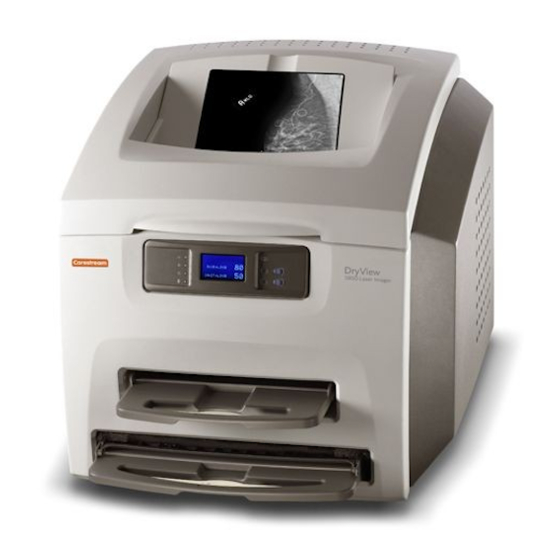
Kodak Dryview 5800 User Manual
Laser imager
Hide thumbs
Also See for Dryview 5800:
- Service manual (328 pages) ,
- User manual (78 pages) ,
- Safety manual (22 pages)
Table of Contents
Advertisement
Quick Links
Advertisement
Table of Contents

Related Manuals for Kodak Dryview 5800


Summary of Contents for Kodak Dryview 5800
- Page 1 KODAK DRYVIEW 5800 Laser Imager CARESTREAM DRYVIEW 5850 Laser Imager User’s Guide...
-
Page 3: Table Of Contents
DRYVIEW 5800 and 5850 Laser Imagers - - - - - - - - - - - - - - - - - - - - - - - - - - - - - - - - - -... - Page 4 Table of Contents Clearing Film Jams - - - - - - - - - - - - - - - - - - - - - - - - - - - - - - - - - - - - - - - - - - - - - - - - - - - - - - - - 3-13 Film Jam - Code 2x-116 - - - - - - - - - - - - - - - - - - - - - - - - - - - - - - - - - - - - - - - - - - - - - - - - - - 3-14 Film Jam - Code 2x126 - - - - - - - - - - - - - - - - - - - - - - - - - - - - - - - - - - - - - - - - - - - - - - - - - - - 3-17 Film Jam - Code 26325 - - - - - - - - - - - - - - - - - - - - - - - - - - - - - - - - - - - - - - - - - - - - - - - - - - - 3-19...
-
Page 5: Overview
Chapter 5 of this manual. Intended Use The KODAK DRYVIEW 5800 Laser Imager provides high quality hard copy film output from digital imaging source modalities for use in medical imaging diagnosis and referral. Electronic image information signals are managed and transformed optically to expose KODAK DRYVIEW media. -
Page 6: How The Laser Imager Works
Overview How the Laser Imager Works The imager is a network printer connected on a network along with one or more medical imaging devices. It prints images sent over the network from medical imaging devices or workstations sending images concurrently. Modality Network Modality... -
Page 7: System Components
Overview System Components Film trays. Your imager is configured with two film trays. Each film tray holds a different size of film. Both film trays must be installed in order for the imager to operate. Film feed transport. The film feed transport orients and centers the film while moving the film from the film tray to the imaging portion of the imager. -
Page 8: Print Sequence
Overview Print Sequence When the imager receives a print request, it determines the requested film size and type and then it selects the appropriate film tray. Each time the imager receives a print request, the following print sequence occurs: 1. Suction cups in the pickup area lift a single sheet of film out of the tray and feed the film into the transport rollers. -
Page 9: Automatic Image Quality Control
Overview Automatic Image Quality Control An internal densitometer is a key element in the Automatic Image Quality Control (AIQC) process. The densitometer enables the imager to automatically adjust image processing parameters to produce the best image. The imager adjusts these parameters each time it prints a calibration film. A calibration film is printed when: •... -
Page 11: Using And Maintaining The Imager
Using and Maintaining the Imager Operator Control of the Imager During normal operation, the imager receives and automatically prints images sent by modalities over a network. Very little operator control is required. The main responsibilities of the operator are described in the following section, along with overview information about using the imager. -
Page 12: Local Panel And Display Screen
Using and Maintaining the Imager Local Panel and Display Screen Local Panel / Display Screen Ready LED. When steady on, the LED indicates that the imager is ready for printing. When flashing, the imager is processing and printing films. When unlit, the imager is not ready to print. -
Page 13: Display Screen Icons
Using and Maintaining the Imager Display Screen Icons Icon Description This icon indicates that film calibration is required. The imager is unable to print jobs from this tray until a successful calibration occurs. This icon indicates that a door is open on the imager. This icon indicates an error with the film tray. - Page 14 Using and Maintaining the Imager Icon Description Icons in Menu Selection Mode The following icons appear on the display screen when you are in Menu Selection Mode. These icons represent the changed functionality of the buttons on the right side of the local panel. While in Menu Selection Mode, press the button (6 in the graphic on page 2-2) to display the Test Print or Maintenance Reset screen.
-
Page 15: Web Portal
Using and Maintaining the Imager Web Portal The Web Portal is your interface to additional functions on the imager. In the Web Portal, you can view and manage the imager's connections over the network, configure features, and view and correct error messages and general status. -
Page 16: Accessing The Web Portal
Using and Maintaining the Imager Accessing the Web To access the Web Portal, you will need a desktop or laptop computer that is Portal connected to the network. 1. On a desktop or laptop computer, start MICROSOFT INTERNET EXPLORER. 2. In the address field, type: http://<IP address> NOTE: <IP address>... -
Page 17: Operations
Using and Maintaining the Imager Operations Unloading and IMPORTANT: Leave the imager powered on while loading or unloading loading the Film Tray the film tray. When 100 sheets of film have been used, a 0 film count appears on the display screen. - Page 18 Using and Maintaining the Imager Bag holder Film package Diverter 4. Pull the diverter (plastic bar) and bag holder (silver bar) into the up position. 5. Press the new film package down in the tray with the label facing up. 6.
- Page 19 Using and Maintaining the Imager Tear strip 10. Remove the tear strip from the plastic bag. 11. Swing the diverter of the film tray back in place. IMPORTANT: Do not install the film saver onto the film tray. 12. Slide the tray back into the imager slot. Plastic bag 13.
-
Page 20: Inserting The Film Saver And Removing The Film Tray
Using and Maintaining the Imager Inserting the Film A film saver must be inserted into a film tray before: Saver and Removing • The hood is opened. the Film Tray • Any panel on the imager is removed. • Film tray with film in it is removed. 1. -
Page 21: Calibration Prints
Using and Maintaining the Imager Calibration Prints imager calibration is performed by printing a calibration print. A calibration print has a step wedge pattern with a series of 26 stripes of increasing optical density. The only purpose of a calibration print is to calibrate the imager. -
Page 22: Working With Quality Test Prints
Using and Maintaining the Imager Working with Quality The imager can print an internally generated density test print with a Test Prints SMPTE pattern. Density test prints can be used as a quality assurance tool to verify the uniformity of films printed by the imager. The 5850 Laser Imager provides additional test images that can be used for mammography quality control. -
Page 23: Operator Maintenance
Using and Maintaining the Imager Operator Maintenance Changing the Charcoal Filter CAUTION In the U.S., exhausted charcoal filters are considered to be non-hazardous waste according to the U.S. Environmental Protection Agency Resource Conservation Recovery Act (RCRA). Municipality owned and licensed solid waste management facilities are an appropriate disposal option. - Page 24 Using and Maintaining the Imager 3. Raise the hood. 4. Pull the front panel forward. 5. Remove the charcoal filter by lifting it up and pulling it forward. 6. Install a new charcoal filter. 7. Close the front panel. 8. Close the hood. 9.
-
Page 25: Troubleshooting
Troubleshooting Error and Alarm Indications The imager can detect errors and other conditions that require operator action. These errors or abnormal conditions are reported on the display screen and on the Web Portal in the form of condition codes and messages. -
Page 26: Printer Status Messages
Troubleshooting Printer Status Messages The following table describes how the local panel and Web Portal indicate printer status to the user. Table 3-2: Printer Status Messages Printer Web Portal Local Panel DICOM Status Description Status Display Any Film • Ready LED off Not Ready WARNING / At least one of the film... -
Page 27: Film Tray Status Messages
Troubleshooting Table 3-2: Printer Status Messages (Continued) Printer Web Portal Local Panel DICOM Status Description Status Display Warming • Ready LED off Warming=xx WARNING / The Processor is warming • Warming LED on PROC INIT up and will not be ready to •... - Page 28 Troubleshooting Table 3-3: Film Tray Status Messages (Continued) Film Tray Web Portal Local Panel Description State Display Manual Mode • Attention LED on The film in this film tray does • Status code: 21002 (upper), not meet AIQC standards. 23002 (lower) However, the user has selected •...
-
Page 29: Job Manager Status Messages
Troubleshooting Job Manager Status Messages The following table describes how the local panel and Web Portal indicate job status to the user. Table 3-4: Job Manager Status Messages Job Manager Web Portal Display Screen Description Status Display Active Shows how many The imager is accepting DICOM job jobs having this requests and film is available for all current... -
Page 30: Condition Codes
Troubleshooting Condition Codes Condition codes are shown on the display screen in the order in which they are generated. If there is more than one code associated with the current condition of the imager, the first code is shown on the display screen for six seconds, while other codes in the list are displayed for three seconds as the list is cycled. - Page 31 Troubleshooting Table 3-5: Condition Codes (Continued) Code Web Portal Message User Action 10003 MIS: Image Buffer Error 1. Shut down the imager, then start the imager. 2. If the error persists, call for service. 10015 MIS: Database Error 1. Shut down the imager, then start the imager. 2.
- Page 32 Troubleshooting Table 3-5: Condition Codes (Continued) Code Web Portal Message User Action 20703 none 1. Press and hold the Menu Selection button for five seconds. 2. Press and release the Menu Selection button again to display the Error Reset menu. Delete the jobs in the Unprintable Jobs Queue.
- Page 33 Troubleshooting Table 3-5: Condition Codes (Continued) Code Web Portal Message User Action 21119 or xxxxx Supply: Internal 1. Cover the film tray with the film saver. Remove the 23119 Hardware Failure tray from the imager. 2. Re-insert the film tray and remove the film saver. 3.
- Page 34 Troubleshooting Table 3-5: Condition Codes (Continued) Code Web Portal Message User Action 21146 or xxxxx Supply: Unsupported 1. The imager has not been configured to use this film 23146 Film Size size. 2. Try a different film size or reconfigure the imager. 3.
- Page 35 Troubleshooting Table 3-5: Condition Codes (Continued) Code Web Portal Message User Action 27123 Optics: Internal Hardware 1. Shut down the imager, then start the imager. Failure 2. If the error persists, call for service. 27601 Optics: Calibration Failed 1. Shut down the imager, then start the imager. 2.
- Page 36 Troubleshooting Table 3-5: Condition Codes (Continued) Code Web Portal Message User Action 28931 Processor: Internal 1. Shut down the imager, then start the imager. Communications Failure 2. If the error persists, call for service. 29154 Densitometer: Internal 1. Shut down the imager, then start the imager. Communications Failure 2.
-
Page 37: Clearing Film Jams
Troubleshooting Clearing Film Jams CAUTION Shutting off power to clear a film jam is not required. Jam Areas and Film Path 2011-09-09 2G0733 3-13... -
Page 38: Film Jam - Code 2X-116
Troubleshooting Film Jam - Code 1. Remove the film trays (see “Inserting the Film Saver and Removing 2x-116 the Film Tray”). Film tray slots 2. Remove any misplaced films from Area 1. This area can be accessed through the film trays slots. NOTE: If the film is not accessible from the front of the imager, continue with... - Page 39 Troubleshooting Hood Left panel 2 thumb screws 3. Open the hood. 4. Loosen the 2 thumb screws and remove the left panel. 2011-09-09 2G0733 3-15...
- Page 40 Troubleshooting Pickup access areas 5. Remove any misplaced films seen in the pickup access areas. 6. If Area 1 did not contain misplaced films, take the film trays to a dark room and remove the film saver. Remove any misplaced films and cover the tray with the film saver.
-
Page 41: Film Jam - Code 2X126
Troubleshooting Film Jam - Code 1. Remove the film trays (see “Inserting the Film Saver and Removing 2x126 the Film Tray”). Film tray slots 2. Remove any misplaced films from Area 1. This area can be accessed through the film trays slots. 3. - Page 42 Troubleshooting Hood Left panel 2 thumb screws 5. Open the hood. 6. Loosen the 2 thumb screws and remove the left panel. Pickup access areas 3-18 2G0733 2011-09-09...
-
Page 43: Film Jam - Code 26325
Troubleshooting 7. Remove any misplaced films seen in the pickup access areas. 8. Set the left panel in place and tighten the 2 thumb screws. 9. Close the hood. Film Jam - Code IMPORTANT: If this error occurred at the same time as 2x-126, follow the 26325 instructions for “Film Jam - Code... - Page 44 Troubleshooting 4. Carefully remove any films found in the drum area. 5. Close the drum cover and secure the cover latches. If the film was not found in the drum area, continue with Step Hood Left panel 2 thumb screws 6.
-
Page 45: Film Jam - Code 26544
Troubleshooting Film advance knob 8. Use the manual advance knob to move the film through the processor. 9. Set the left panel in place and tighten the 2 thumb screws. 10. Close the hood. If film was not previously removed, the misplaced films will emerge from the imager within two minutes. -
Page 46: Calling For Support
Troubleshooting Calling for Support If you cannot correct a condition and need help, call for support. Have the following information ready when you call: • Model Number • Serial Number or K-Number • Condition code and message if they are shown on the display screen and Web Portal 3-22 2G0733... -
Page 47: Film Technical Information
Film Technical Information General Description This section describes the characteristics of laser imaging film, not the operation of the laser imager. The laser imaging film is a high-resolution, infrared-sensitive, photothermographic film designed specifically for the laser imager. The laser imaging film is packaged in daylight-load packages and is available in blue, clear, and mammography film types. -
Page 48: Environmental Impact
Film Technical Information Environmental Tests show that the laser imaging film is not considered hazardous to the Impact environment. As a result, you can develop, recycle, and dispose of film with less impact on the environment than if you were using wet-developed silver halide films. -
Page 49: Archiving Developed Film
Film Technical Information lighting. This is virtually undetectable and has no effect on image quality (typically 0.02 change in density). This small density increase is uniform and permanent upon full exposure of the film under normal handling conditions (room light or view box). Archiving Developed The laser imaging film has been tested and can be archived for more than Film... -
Page 51: Specifications
Specifications Location Equipment Specifications Unpacked Packed Height 62 cm (24 in.) 95 cm (37 in.) Width 62 cm (24 in.) 81 cm (32 in.) Depth 66 cm (26 in.) without film trays 106 cm (42 in.) 76 cm (30 in.) with film trays Weight 70 kg (155 lb) 147.4 kg (325.0 lb) -
Page 52: Other Location Considerations
Specifications Other Location Additional factors that influence where the imager is located include Considerations proximity to patients, flammable materials, liquids, and other equipment. CAUTION This equipment is not contained in a sealed cabinet. Do not use this equipment in locations where it can come in contact with liquids, including body fluids. -
Page 53: Environmental Requirements
Specifications Environmental Requirements Temperature • Operating: 15–33 °C (59–91 °F) • Storage: From –40 through 60 °C (From –40 through 140 °F) Relative Humidity • Operating: 20–80 % RH, noncondensing • Storage: 10–90 % RH, noncondensing Altitude 30 m (100 ft) below sea level to 2438 m (8000 ft) above sea level Surface Condition The surface must be a level (must be level within 1 °) table top or counter capable of supporting the weight of the imager. -
Page 54: Power Requirements
KODAK DRYVIEW DVB+ Laser Imaging Film • KODAK DRYVIEW DVB+ Premium Laser Imaging Film • 5850 Laser Imager only: KODAK DRYVIEW Mammography Laser Imaging Film and KODAK DRYVIEW DVM+ Mammography Laser Imaging Film NOTE: Not all film types are available in every country. 2G0733... -
Page 55: Film Sizes
Specifications Film Sizes The imager accommodates the following film sizes: • 20 x 25 cm (8 x 10 in.) • 25 x 30 cm (10 x 12 in.) • 28 x 35 cm (11 x 14 in.) • 35 x 35 cm (14 x 14 in.) •... -
Page 57: Glossary
Glossary Computed Radiography, the process of creating digital radiographic images. Computed Tomography, the process of creating digital tomographic images. Cycle power Cycle power means to shut down and power up the Laser Imager. DICOM Digital Imaging and Communications in Medicine. A TCP/IP-based protocol for transmitting and receiving medical imaging and related data over a network. - Page 58 Glossary Test type The type of test film that will be printed. Two film test types are available: a density test film (SMPTE pattern) and a calibration film. Transfer Function Tables. Unprintable queue The queue of jobs that cannot be printed because of problems with the job description.
- Page 59 Index Agency compliance, 1-5 Job manager status messages, 3-5 Altitude, 5-3 Automatic image quality control (AIQC), 1-5 Laser specifications, 5-3 Local panel layout, 2-2 Calling for support, 3-22 Conventions, 1-5 Correcting film jams, 3-13 MCS printer status messages, 3-2 Messages DICOM printer status, 3-1 DICOM, 1-1 Film supply status, 3-3...
- Page 61 Publication History Revision Date Reason for Change 2008-01-14 First release 2009-02-27 Incorporated details for 5850 Laser Imager. 2009-05-06 Updated the Intended Use statement for the 5850 Laser Imager 2011-09-09 Modified formatting of dates and measurements (EN 1041)
- Page 62 Carestream Health, Inc. 150 Verona Street Rochester, NY 14608 © Carestream Health, Inc., 2011 CARESTREAM and DRYVIEW are trademarks of Carestream Health, Inc. The Kodak trademark and trade dress are used under license from Kodak. Pub No. 2G0733 Rev. D...
Need help?
Do you have a question about the Dryview 5800 and is the answer not in the manual?
Questions and answers