Table of Contents
Advertisement
SAFETY NOTICE:
If this appliance is not properly installed, a house fire may
result. For your safety, follow the installation directions.
Contact local building or fire officials about restrictions
and installation inspection requirements in your area.
Owner's Manual
Copyright 2007, T.I.
$10.00
93508061
4050526
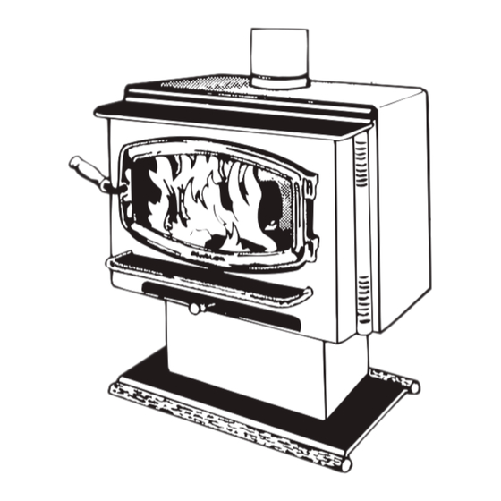
Olympic
( 1 1 9 0 )
Wood Stove and
Fireplace Insert
Residential Freestanding Stove
Mobile-Home Freestanding Stove
Alcove Approved
Hearth-Stove Approved
Masonry Fireplace Insert
Save these instructions
for future reference
Listed:
OMNI-Test Laboratories, Inc.
Beaverton, Oregon
Tested to: U.L. 1482
Report # 028-S-27-2 (June, 1999)
Advertisement
Table of Contents

Related Manuals for Travis Industries Avalon Olympic


Summary of Contents for Travis Industries Avalon Olympic
-
Page 1: Safety Notice
Olympic ( 1 1 9 0 ) Wood Stove and Fireplace Insert Residential Freestanding Stove Mobile-Home Freestanding Stove Alcove Approved Hearth-Stove Approved Masonry Fireplace Insert Save these instructions for future reference SAFETY NOTICE: If this appliance is not properly installed, a house fire may result. -
Page 2: General Information Introduction & Important Information
Introduction Introduction We welcome you as a new owner of an Avalon Olympic wood-burning stove. In purchasing an Avalon Olympic you have joined the growing ranks of concerned individuals whose selection of an energy system reflects both a concern for the environment and aesthetics. The Avalon Olympic is one of the finest appliances the world over. -
Page 3: Table Of Contents
Insert with Direct Connection (Masonry Fireplace) ..23 Stove Legs ..............40 Pedestal ..............40 Rear Blower Installation ..........42 Outside Air Boot Installation ........43 Surround Panels ............44 Front Blower ............... 45 ................46 Index © Travis Industries 93508061 4050526... -
Page 4: Safety Precautions
Type Clay cause a house fire. residential type chimney or an Liner Do not connect this appliance to approved masonry chimney with any chimney serving another a standard clay tile, or stainless appliance. steel liner. © Travis Industries 93508061 4050526... - Page 5 Avoid placing wood against the glass when loading. Do not slam the door or strike the glass. Do not throw this manual away. Travis Industries, Inc. grants This manual has important no warranty, implied or This operating and maintenance...
-
Page 6: Features & Specifications
* For inserts, add 1" for the flue collar. 20-1/2"** ** See "Fireplace Requirements" for details on fireplace insert installation. Figure 1 Emissions 2.6 Grams Per Hour (EPA Phase II Approved) – Tests conducted by E.E.S.P.C. © Travis Industries 93508061 4050526... -
Page 7: Stove Installation
Planning The Installation We suggest that you have an authorized Travis Industries dealer install your stove. If you install the stove yourself, your authorized dealer should review your installation plans. Check with local building officials for any permits required for installation of this stove and notify your insurance company before proceeding with installation. -
Page 8: Floor Protection Requirements
(for qualified installers only) Floor Protection Requirements Stove must be placed on the Travis Industries legs or Pedestal. Floor protection must extend 6" to the sides and rear of the stove and 16" to the front of the stove (41-3/8"... -
Page 9: Travis Industries
Measure rear and side clearances from the nearest edge of the stove top. NOTE: vent diameter varies depending on brand and model. 16” Min. Floor Protection Measure front clearances from the face of the stove (unibody). Figure 3 © Travis Industries 93508061 4050526... -
Page 10: Chimney Requirements
Drafting barometric pressure, topography, or factors of the home (negative pressure from exhaust Performance fans, chimneys, air infiltration, etc.), may adversely affect draft. Travis Industries can not be responsible for external forces leading to less than optimal performance. Standard residential installations may use single-wall connector (Mobile-Homes may not) ... -
Page 11: Chimney Termination Requirements
Air may be drawn from a ventilated Outside air entrance must be placed so crawl space or use an air duct. it does not become blocked by snow. Figure 6 © Travis Industries 93508061 4050526... -
Page 12: Alcove Installation Requirements
Minimum height of alcove 84" 6" above stove top Non-combustible alcove construction (on walls and ceiling) - see the explanation above. Ventilated air space 3 1/2" thick non- combustible material 1" Min. Non-combustible reinforcer Figure 7 © Travis Industries 93508061 4050526... -
Page 13: Mobile Home Requirements
Minimum Stove home (consult your building official). Clearance (as outlined above) WARNING:DO NOT INSTALL IN SLEEPING ROOM. CAUTION:THE STRUCTURAL INTEGRITY OF THE MOBILE HOME FLOOR, WALL, AND CEILING/ROOF MUST BE MAINTAINED. Figure 9 © Travis Industries 93508061 4050526... -
Page 14: Standard Ceiling With A Factory Built Chimney
(some require a radiation usually 2") shield). Minimum 15' Chimney Maximum 33' Connector Sections Floor Protection Stove Clearances (See the section "Floor (See the section "Stove Protection Requirements" Placement Requirements" for more details) for more details) Figure 11 © Travis Industries 93508061 4050526... -
Page 15: Exterior Factory Built Chimney
Airtight Insulated Clean-Out installation and support. Remove damper or wire it open Floor Protection (See the section "Floor Protection See the section Requirements" "Stove Placement for more details) Requirements" for minimum clearances required. Figure 13 © Travis Industries 93508061 4050526... -
Page 16: Hearth Stove Direct Connection
UBC approved Placement Requirements" for masonry connector minimum clearances required. or a factory built (U.L. Listed) wall thimble. Chimney connector sections See the section Make sure the "Floor Protection clean-out seals in Requirements" place. Figure 15 © Travis Industries 93508061 4050526... -
Page 17: Fireplace Insert Installation
Planning The Installation We suggest that you have an authorized Travis Industries dealer install your fireplace insert. If you install the fireplace insert yourself, your authorized dealer should review your installation plans. Check with local building officials for any permits required for installation of this fireplace insert and notify your insurance company before proceeding with installation. -
Page 18: Top Air Chamber Extension
3. Attach the grill to the air chamber top. Attach the bypass extension rod included in the owner’s kit to the damper yoke. Attach the bypass pull ring to the extension rod to complete the installation. © Travis Industries 93508061... -
Page 19: Fireplace Requirements
Mantel Shield 38-1/4" 39-1/4" * This is the distance the insert protrudes from Mantel Height 53-1/4" 54-1/4" the fireplace opening plus the required 16" of with Mantel Shield 40-1/4" 41-1/4" hearth extension. Figure 16 © Travis Industries 93508061 4050526... -
Page 20: Insert Placement Requirements
Entire fireplace, including chimney, must be clean and undamaged. Any damage must be repaired prior to installation of the insert Chimney height: 15' minimum; 33' maximum. Entire fireplace, including chimney, must meet local building requirements © Travis Industries 93508061 4050526... -
Page 21: Drafting Performance
This appliance relies upon natural draft to operate. External forces, such as wind, barometric pressure, topography, or factors of the home (negative pressure from exhaust fans, chimneys, air infiltration, etc.), may adversely affect draft. Travis Industries can not be responsible for external forces leading to less than optimal performance. -
Page 22: Block-Off Plate Installation
Measurement "C" See the dimensions to determine the location of the Measurement "B" center of the Firebox flue. See the dimensions to determine the location of the center of the flue. Figure 19 © Travis Industries 93508061 4050526... -
Page 23: Insert With Positive Connection
(see "Block-off Insulated Plate Installation" on Clean-Out page 22). Remove Surround Panels damper or wire it open See the section "Insert Placement Block-off plate or Requirements" for damper adapter minimum clearances and hearth required. © Travis Industries 93508061 4050526... -
Page 24: Travis Industries
Surround Panels with insulation (see "Surround Panels" installation instructions in the back of the manual) Airtight Insulated Clean-Out See the section "Insert Placement Requirements" for minimum clearances and hearth required. Remove damper or wire it open © Travis Industries 93508061 4050526... -
Page 25: Operating Your Appliance
The door becomes hot during use. Use a glove to open the door if the handle is hot. To prevent smoke from entering the room, open the bypass before opening the door (see following page for directions). You can also open the door a small amount and let air enter the firebox. © Travis Industries 93508061 4050526... -
Page 26: Bypass Operation
When starting or re-loading, pull the bypass out. During normal operation, push the bypass in. Bypass Pulled Out Used for starting and re-loading Use the included pull tool to operate the bypass rod Bypass Pushed In Used for normal operation © Travis Industries 93508061 4050526... -
Page 27: Starting A Fire
This should start the chimney drafting (this eliminates "cold air blockage"). Use plenty of kindling to ensure the stove reaches a proper temperature. Once the kindling is burning rapidly, place a few larger pieces of wood onto the fire. © Travis Industries 93508061 4050526... -
Page 28: Adjusting The Burn Rate
If the ashes are disposed of by burial in soil or otherwise locally ASHES dispersed, they should be retained in the closed container until all cinders have thoroughly cooled. © Travis Industries 93508061 4050526... -
Page 29: Optional Blower Operation
- this is normal. Blower Sounds: The blower will make a slight "humm" as it pushes air through the stove. Hint: Make sure the leveling bolts on legs are extended - preventing the hearth from amplifying any vibrations. © Travis Industries 93508061 4050526... -
Page 30: Hints For Burning
Wood Cutting and Storage Cut wood to length and Store the wood off the ground in a chop into quarters. covered area. Allow for airflow Air Flow around the wood to dry the wood. Air Flow Air Flow © Travis Industries 93508061 4050526... -
Page 31: Troubleshooting
See the section "Door and Glass Inspection" on page 33 for details. Check the ash bed for coals. Often, coals are still glowing under a slight bed of flyash. By raking these into a pile you can re-start your stove quickly. © Travis Industries 93508061 4050526... -
Page 32: Maintaining Your Appliance
The ash acts as a light abrasive. The glass will develop a very slight haze over time. This is normal and will not affect viewing of the fire. © Travis Industries 93508061 4050526... -
Page 33: Monthly Maintenance
If you are not certain of creosote inspection, contact your dealer or local chimney sweep for a full inspection. Excess creosote buildup may cause a chimney fire, that may result in property damage, injury, or death. © Travis Industries 93508061 4050526... -
Page 34: Yearly Maintenance
Slight scaling or rusting of the metal is normal. Make sure the push pins hold the air tubes in place. Floor and Wall Firebricks - replace any severely damaged firebrick along the side or floor of the firebox. © Travis Industries 93508061 4050526... -
Page 35: Door Parts
You may need to open and close the door repeatedly to get the gasket to seat fully. Replacing the Door Handle See the illustration above for a component list (see pg. 33 for details on adjusting the door). © Travis Industries 93508061 4050526... -
Page 36: Firebox Parts
Do not pry firebrick - they chip and crack easily. Remove the floor firebricks first. The side firebrick are removed later because they are pinned in place by the floor firebrick. Clean the firebox prior to replacing the firebrick. © Travis Industries 93508061 4050526... -
Page 37: Baffle Removal And Replacement
Air Tube Removal & Replacement Air Tube Collar Air Tube Remove the left pin on the air tube collar Roll Pin Slide the air tube to the left, swing it down and remove from the firebox. © Travis Industries 93508061 4050526... - Page 38 Limited 7 Year Warranty To register your TRAVIS INDUSTRIES, INC. 7 Year Warranty, complete the enclosed warranty card and mail it within ten (10) days of the appliance purchase date to: TRAVIS INDUSTRIES, INC., 4800 Harbour Pointe Blvd. SW, Mukilteo, WA 98275. TRAVIS INDUSTRIES, INC. warrants this gas appliance (appliance is defined as the equipment manufactured by Travis Industries, Inc.) to be defect-free in material and workmanship to the original purchaser from the date of purchase as follows:...
-
Page 39: Listing Information
10850 117th Pl. N.E. Kirkland, WA 98033 U.S. ENVIRONMENTAL PROTECTION AGENCY Certified to comply with July 1990 particulate emission standards. DATE OF MANUFACTURE 1999 2000 2001 Jan. Feb. Mar. Apr. June July Aug. Sep. Oct. Nov. Dec. © Travis Industries 93508061 4050526... -
Page 40: Optional Equipment
Pedestal The dowels insert onto If using outside air, tuck the front and back edge the insulation under the of the pedestal base. sides of the pedestal. © Travis Industries 93508061 4050526... - Page 41 Remove the two screws that hold the bridge to the cover plate. Then replace Air Control the bridge when the cover plate is in place. The cover plate has a clip which attaches it underneath the air control. © Travis Industries 93508061 4050526...
-
Page 42: Rear Blower Installation
Attach the quick-connects leading from the snap disk to the Plug the power cord into a 110 V. outlet after installing the quick-connects from the blower blower. (orientation does not matter). © Travis Industries 93508061 4050526... -
Page 43: Outside Air Boot Installation
The hole in the floor (and hearth) must be a minimum 16 square inches. It should be 1/2” smaller than the footprint of the air boot in each dimension to allow for the Floor (and hearth) gasket to seal. © Travis Industries 93508061 4050526... -
Page 44: Surround Panels
Install the top panel so the tabs insert sides if the power cord is routed behind the the fireplace. Use a into the joggle clips on the top panel surround panel. screwdriver to tuck any exposed insulation behind the panels. © Travis Industries 93508061 4050526... -
Page 45: Front Blower
Baseplate of Appliance (Below Ashlip) Front of Insert the baseplate This clip aligns the blower Appliance of the appliance into inside the convection channel. this gap. © Travis Industries 93508061 4050526... -
Page 46: Index
Hearth (Floor Protection - Stove) ......8 Hearth Stove ............16 Heating Specifications ........... 6 Hints for Burns ............30 Installation Options ..........6 Installation (stove) ..........7 Leg Installation ............40 Listing Label ............39 © Travis Industries 93508061 4050526...
Need help?
Do you have a question about the Avalon Olympic and is the answer not in the manual?
Questions and answers