Table of Contents
Advertisement
Quick Links
SAFETY NOTICE:
If this appliance is not properly installed, a house fire may result.
For your safety, follow the installation directions. Contact local
building or fire officials about restrictions and installation
inspection requirements in your area.
12521 Harbour Reach Drive
Mukilteo, WA 98275
French language manual can be found at lopistoves.com
Les manuel en français sont disponibles sur lopistoves.com
Copyright 2019, T.I.
$10.00
8/2/2023
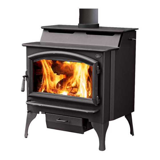
Liberty
Wood Stove
( E P A 2 0 2 0 C o m p l i a n t )
Manual
Freestanding Stove
Mobile Home (US) & Transportable Building
(CAN) Approved
Alcove Approved
Hearth-Stove Approved
Save these instructions for future reference
100-01511
Report #0028WS065S & 0028WS065E
Certified to UL 1482-2022 & CAN/ULC S627-2023
Listed by
Omni-Test Laboratories, Inc.
Advertisement
Table of Contents

Subscribe to Our Youtube Channel
Related Manuals for Travis Industries Lopi Liberty


Summary of Contents for Travis Industries Lopi Liberty
- Page 1 Liberty Wood Stove ( E P A 2 0 2 0 C o m p l i a n t ) Manual Freestanding Stove Mobile Home (US) & Transportable Building (CAN) Approved Alcove Approved Hearth-Stove Approved Save these instructions for future reference SAFETY NOTICE: If this appliance is not properly installed, a house fire may result.
-
Page 2: Introduction
Introduction Introduction We welcome you as a new owner of a Lopi Liberty wood-burning stove. In purchasing a Lopi Liberty you have joined the growing ranks of concerned individuals whose selection of an energy system reflects both a concern for the environment and aesthetics. The Lopi Liberty is one of the finest appliances the world over. -
Page 3: Table Of Contents
Removal .............. 37 Bypass Operation .......... 20 Replacement ............39 Before Starting a Fire ........21 Listing Label ........... 41 Adjusting the Burn Rate ........ 22 © Travis Industries 8/2/2023 - 1511 Liberty... - Page 4 Do not place clothing or other to the floor, have outside air, and not flammable items on or near this Mobile be installed in the bedroom (per appliance. Home H.U.D. requirements). Check with local building officials. © Travis Industries 8/2/2023 - 1511 Liberty...
- Page 5 Burn the fire directly on the bricks. Avoid placing wood against the glass when loading. Do not slam the door or strike the glass. Travis Industries, Inc. grants no Do not throw this manual away. This warranty, implied or stated, for the...
-
Page 6: Installation Options
This heater meets the 2020 U.S. EPA’s cord wood emission limits for wood heaters. Tested to EPA Alt-125, ASTM E3053-17, ASTM 2515-11, CSA B415.1-10 this heater has been shown to deliver heat at rates ranging from 15,155 to 63,239 BTU/hr and an emission value of 2.5g/h. Report No. 0028WS062E © Travis Industries 8/2/2023 - 1511 Liberty... -
Page 7: Planning The Installation
Planning The Installation We suggest that you have an authorized Travis Industries dealer install your stove. If you install the stove yourself, your authorized dealer should review your installation plans. Check with local building officials for any permits required for installation of this stove and notify your insurance company before proceeding with installation. -
Page 8: Packing List
Bypass Tool Gloves Floor Protection Requirements Stove must be placed on the Travis Industries legs. Floor protection must extend to the sides, rear, and front of the stove (see “Clearances” below for minimum floor protection). Floor protection must be non-combustible and at least .018" thick (26 gauge). -
Page 9: Clearances - Single Wall Connector
Can. 8" (204mm) 30” (762mm) 9-1/2" (242mm) 6-1/4” (159mm) Connector App. 6" (153mm) dia. 24-7/16” (621mm) US 6" (153mm) Can. 8" (204mm) TOP OF STOVE US 16" (407mm) Can. 18" (458mm) FLOOR PROTECTION © Travis Industries 8/2/2023 - 1511 Liberty... -
Page 10: Clearances - Reduced Clearance Connector10
Standard Masonry Chimney with any one of the above listed connectors Connector App. 7" (178mm) dia. 24-7/16” (621mm) US 6" (153mm) Can. 8" (204mm) TOP OF STOVE US 16" (407mm) Can. 18" (458mm) FLOOR PROTECTION © Travis Industries 8/2/2023 - 1511 Liberty... -
Page 11: Chimney Connector Requirements
(US) or Transportable Building (CAN) must use the clearances listed in this manual under "Additional Requirements for Mobile Home (US) or Transportable Building (CAN) Installations". The Chimney connector must be in good condition and kept clean. © Travis Industries 8/2/2023 - 1511 Liberty... -
Page 12: Chimney Requirements
Inadequate draft may cause backpuffing into the room and `plugging' of the chimney. Inadequate draft will cause the appliance to leak smoke into the room through appliance and chimney connector joints. An uncontrollable burn or excessive temperature indicates excessive draft. © Travis Industries 8/2/2023 - 1511 Liberty... -
Page 13: Chimney Termination Requirements
(10323mm) or 6’ (1.83M) with a minimum cross section of 7 square inches (4517mm). IDB1206 Outside Air Connector Outside air entrance must be placed so it does not become blocked by snow. Figure 4 © Travis Industries 8/2/2023 - 1511 Liberty... -
Page 14: Alcove Installation Requirements
(1220mm) (1220mm) combustible (f) Minimum width of 62” 42” material alcove (1575mm) (1067mm) 1" (25mm) (g) Minimum height of 84” 6” alcove (2134mm) (153mm) Min. above stove top Non-combustible reinforcer IDB1121 IDB1235 © Travis Industries 8/2/2023 - 1511 Liberty... -
Page 15: Mobile Home (Us) Or Transportable Building (Can) Requirements
(as outlined above) WARNING: DO NOT INSTALL IN SLEEPING ROOM. CAUTION: THE STRUCTURAL INTEGRITY OF THE MOBILE HOME (US) OR TRANSPORTABLE BUILDING (CAN) FLOOR, WALL, AND IDB1166 CEILING/ROOF MUST BE MAINTAINED. Figure 6 © Travis Industries 8/2/2023 - 1511 Liberty... -
Page 16: Standard Ceiling With A Factory Built Chimney
Minimum 15' (4.57M) Maximum 33' (10.06M) Connector Pipe Sections Stove Clearances (See the section "Stove Floor Protection Placement Requirements" (See the section "Floor for more details) Protection Requirements" for more details) IDB1123 Figure 8 © Travis Industries 8/2/2023 - 1511 Liberty... -
Page 17: Exterior Factory Built Chimney
Min. 36" (915mm) Remove damper or wire it open Floor Protection See the section (See the section "Stove Placement "Floor Protection Requirements" for Requirements" minimum clearances for more details) required. IDB1125 Figure 10 © Travis Industries 8/2/2023 - 1511 Liberty... -
Page 18: Interior Or Exterior Masonry Chimney
NFPA 211 standard (See the section "Stove Placement Requirements" for more details) Make sure the Floor Protection (See the section "Floor clean-out seals in Protection Requirements" place. for more details) IDB1127 Figure 11 © Travis Industries 8/2/2023 - 1511 Liberty... -
Page 19: Safety Notice
Over-firing may lead to damage of plated surfaces. If you are uncertain of over-firing conditions, we suggest placing a stove thermometer (e.g. Rutland® Model 710) directly over the door on the stove top - temperatures exceeding 800° are generally considered over-firing and will void the warranty. © Travis Industries 8/2/2023 - 1511 Liberty... -
Page 20: Opening The Door
During normal operation, push the bypass in. Use the included pull tool Bypass Pulled Out to operate the bypass rod Used for starting and re-loading Bypass Pushed In Used for normal operation IDB1239 © Travis Industries 8/2/2023 - 1511 Liberty... -
Page 21: Before Starting A Fire
(this eliminates "cold air blockage"). Use plenty of kindling to ensure the stove reaches a proper temperature. Once the kindling is burning rapidly, place a few larger pieces of wood onto the fire. © Travis Industries 8/2/2023 - 1511 Liberty... -
Page 22: Adjusting The Burn Rate
The air control may become hot during operation - use gloves or a tool to prevent burns. The air control may take several minutes to influence the burn rate. When making adjustments, you may wish to let the stove burn for 10 minutes to gauge performance. © Travis Industries 8/2/2023 - 1511 Liberty... -
Page 23: Understanding Your Heater's Combustion System
If you are unsure how well your heater is burning look at the chimney cap to monitor visible emissions. © Travis Industries 8/2/2023 - 1511... -
Page 24: Burning Your Heater
© Travis Industries 8/2/2023 - 1511... -
Page 25: Ash Removal
1. Twist the ash pan handle down and pull out the ash pan. 2. Lift out the ash pan by the edges and use the handle to transport the ash pan to the metal container. © Travis Industries 8/2/2023 - 1511... -
Page 26: Optional Blower Operation
Blower Sounds: The blower will make a slight "humm" as it pushes air through the stove. Hint: Make sure the leveling bolts on legs are extended - preventing the hearth from amplifying any vibrations. © Travis Industries 8/2/2023 - 1511 Liberty... -
Page 27: Hints For Burning
When burned wet wood must release water stored within the wood. This cools the fire, creates creosote, and hampers a complete burn. Ask any experienced wood burner and he or she will agree: dry wood is crucial to good performance. Wood Cutting and Storage © Travis Industries 8/2/2023 - 1511 Liberty... -
Page 28: Do Not Burn List
Burning these materials may result in release of toxic fumes or render the heater ineffective and cause smoke. © Travis Industries 8/2/2023 - 1511 Liberty... -
Page 29: Troubleshooting
By raking these into a pile you can re-start your stove quickly. Check ash pan seal. Ash pan door must be closed tight and gasket must make a good seal. © Travis Industries 8/2/2023 - 1511 Liberty... -
Page 30: Daily Maintenance (While Stove Is In Use)
The ash acts as a light abrasive. The glass will develop a very slight haze over time. This is normal and will not affect viewing of the fire. © Travis Industries 8/2/2023 - 1511 Liberty... -
Page 31: Monthly Maintenance (While Appliance Is In Use)
Tighten the nut and test operation. You may need to repeat this process, either moving the nut inwards or outwards, until the door catch is in the correct position. Door Handle © Travis Industries 8/2/2023 - 1511 Liberty... -
Page 32: Creosote - Formation And Need For Removal
Floor and Wall Firebricks - replace any severely damaged firebrick along the side or floor of the firebox. Bypass Rod IDB1245 & Yoke Slide Plate Ceramic Fiber Baffle Blanket Damper Plate Air Tube & Pin Baffle Board © Travis Industries 8/2/2023 - 1511 Liberty... -
Page 33: Door Parts
You may need to open and close the door repeatedly to get the gasket to seat fully. Replacing the Door Handle See the illustration above for a component list (see pg. 31 for details on adjusting the door). © Travis Industries 8/2/2023 - 1511 Liberty... -
Page 34: Firebox Parts
Do not pry firebrick - they chip and crack easily. Remove the floor firebricks first. The side firebricks are removed later because they are pinned in place by the floor firebrick. Clean the firebox prior to replacing the firebrick. © Travis Industries 8/2/2023 - 1511 Liberty... -
Page 35: Air Tube Removal & Replacement
The pin will then disengage from the air tube (you may wish to rotate the tube slightly). IDB1152 Pivot the air tube downwards and slide it out of the air channel on the opposite side. © Travis Industries 8/2/2023 - 1511 Liberty... -
Page 36: Air Tube Identification
NOTE: The baffle rests on the top of the air tubes. Make sure to support the baffle while removing the tubes. Bypass Rod IDB1245 & Yoke Slide Plate Ceramic Fiber Baffle Blanket Damper Plate Air Tube & Pin Baffle Board © Travis Industries 8/2/2023 - 1511 Liberty... -
Page 37: Removal
Push up on the baffle slightly and slide the front air tube to the left until the end is clear of the manifold. Lower the right end of the tube and maneuver left end of the tube out of the manifold on the left side of the firebox. Remove the baffle cap. © Travis Industries 8/2/2023 - 1511 Liberty... - Page 38 Gently slide the baffle board and blanket forward until it is free of the rear air tube. Lower the front edge of the baffle and fold the edges of the blanket inward. © Travis Industries 8/2/2023 - 1511 Liberty...
-
Page 39: Replacement
NOTE: Make sure that the fiber blanket is underneath the damper plate in the rear of the firebox when reassembling. Make sure the baffle is above the rear tube and the blanket is below the baffle plate © Travis Industries 8/2/2023 - 1511 Liberty... - Page 40 16. If for any reason any section of this warranty is declared invalid, the balance of the warranty remains in effect and all other clauses shall remain in effect. 17. This 7 year warranty is the only warranty supplied by Travis Industries, Inc., the manufacturer of the appliance. All other warranties, whether express or implied, are hereby expressly disclaimed and purchaser’s recourse is expressly limited to the warranties set forth herein.
-
Page 41: Listing Label
Listing Information Listing Label © Travis Industries 8/2/2023 - 1511 Liberty... - Page 42 Notes © Travis Industries 8/2/2023 - 1511 Liberty...
- Page 43 Notes © Travis Industries 8/2/2023 - 1511 Liberty...
- Page 44 Why Dry Wood is Key ........27 Firebox Parts ............ 34 Wood Cutting and Storage ......27 Firebrick and Baffle Inspection ......32 Yearly Maintenance ......... 32 Floor Protection Requirements ......8 Hearth Stove Positive Connection ....17 © Travis Industries 8/2/2023 - 1511 Liberty...
Need help?
Do you have a question about the Lopi Liberty and is the answer not in the manual?
Questions and answers