
Related Manuals for Response Alarms PA6


Summary of Contents for Response Alarms PA6
-
Page 1: Alarm System
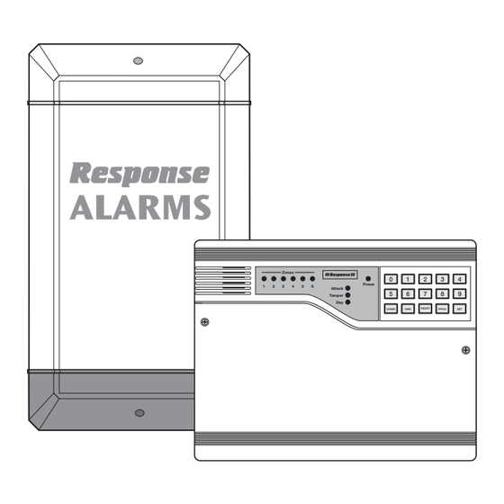
PA6/PA8 6 Zone Wired Intruder Alarm System Zones Power Attack Tamper CHIME OMIT RESET PROG Installation & Operating Manual... -
Page 2: Safety Warnings
FOREWORD The PA6 and PA8 Alarm Systems are designed for ease of Note: Where a Control Panel Back-up Battery is not installation using only conventional domestic tools. However, readily available it is recommended that the Control it is essential that the installer reads and fully understands the... -
Page 3: Table Of Contents
INSTALLING THE PIR MOVEMENT DETECTORS ALARM RECORD Mounting The PIR Movement Detectors Wiring The PIR Movement Detectors TROUBLE SHOOTING Testing The PIR Movement Detectors At The Control Panel EXTENDING YOUR ALARM SYSTEM TYPICAL WIRING ARRANGEMENTS 12-13 COMPONENT SPECIFICATION Back Cover PA6/PA8 Alarm... -
Page 4: Kit Contents
KIT CONTENTS The PA6 and PA8 Alarm kits contain the following components. Zones Power Attack Tamper CHIME OMIT RESET PROG Control Panel Zone 1 Zone 2 Zone 3 Zone 4 Zone 5 Zone 6 Zone 7 Zone 8 Tamper Chime... -
Page 5: Introduction & Overview
INTRODUCTION & OVERVIEW The PA6 and PA8 Alarm kits contain all components This is because the PIR detectors require a period of necessary to install a complete system. The items included 3-4 minutes to stabilise before they operate correctly in your package are shown opposite, the main components... -
Page 6: External Siren & Strobe
Entry/Exit sounder can The Control Panel and Remote Keypad are protected from be silenced after just a few seconds. unauthorised disarming by means of initiating a Tamper Alarm if more than 20 incorrect key pushes are made. PA6/PA8 Alarm... -
Page 7: Programmable Zone Options
Second User - not programmed An Instant Program will be Set silently 3 seconds after the Two User Access Codes are available to Arm/Disarm and Exit route has been initiated. test the system. Each code is 4 digit, selectable from PA6/PA8 Alarm... -
Page 8: Planning The Installation
When considering and deciding upon the mounting position tone (emitted by the Control Panel) effectively when setting for the detector the following points should be considered to the system. It is preferable that the Exit tone can be heard ensure trouble free operation: PA6/PA8 Alarm... -
Page 9: External Siren & Strobe
Zone 4 (This is the Zone which will be Plan your cable runs for ease of installation and neatness of final intentionally omitted when the system is armed at night). appearance, allowing for concealing cables where necessary. PA6/PA8 Alarm... -
Page 10: Installing The Control Panel And Remote Keypad
(adjust the screw as required so that it is a snug fit to the keyhole slot). Hold the Control Panel 5. Ensure the Control Panel speaker wires are connected casing in position and mark the two bottom mounting to terminals marked with a speaker symbol. PA6/PA8 Alarm... -
Page 11: Mounting The Remote Keypad
Control Panel PCB following the colour coding indicated above. Removing the TAMP wire link 1. Thread the cable through the entry on the base, then as the wires are connected. strip back 5mm of each core, twist the strand ends PA6/PA8 Alarm... -
Page 12: Testing The Control Panel (And Remote Keypad)
4. Remove the wire links from each Zone in turn. As you do so the panel will beep and the appropriate Zone LED will illuminate. Replace the link to silence the alarm. The Zone LED will remain illuminated. PIR Detection Pattern (90°Spread) PA6/PA8 Alarm... -
Page 13: Mounting The Pir Movement Detectors
Alternatively, the unit can be touch the PIR detector lens. ceiling mounted using the two holes at the extreme top of the casing. Cable entry cut outs are provided top and Continued on Page 14 bottom, as required. PA6/PA8 Alarm... -
Page 14: Typical Wiring Arrangements
GREEN WHITE BLACK BLUE YELLOW YELLOW BLUE GREEN Twist (or Solder) cable cores together WHITE and insulate MAGNETIC CONTACT Wiring diagram for PIR and Magnetic Contact Detector on different zones with all cables returning to the Control Panel PA6/PA8 Alarm... - Page 15 Detector 1 Detector 2 Detector 3 Detector 4 Detector 1 Detector 2 Detector 3 Detector 4 Siren Tamper Connections Series wiring of zone connections from Series wiring 24-hour connections multiple detectors on a single zone from multiple detectors PA6/PA8 Alarm...
-
Page 16: Testing The Pir Movement Detectors At The Control Panel
Contact Switch is held closed by the magnetic All Zone LEDs will extinguish, the Attack, Tamper and field from the Magnet. Opening the protected door or Day LED’s will be illuminated. window will remove the magnetic field and allow the Contact PA6/PA8 Alarm... -
Page 17: Wiring The Magnetic Contacts
Max Gap 9mm (door/window closed) Magnet using two 25mm Counter-sunk fixing screws. Ensure that the parallel gap between the Magnet and Typical position of contact fitted to door Contact Switch positions is no greater than 9mm. PA6/PA8 Alarm... -
Page 18: Testing Magnetic Contacts At The Control Panel
1. Ensure that the mains power is switched off and the Back-up Battery is disconnected at the Control Panel. The External Siren & Strobe should be fitted to the outside of the building in a prominent position that is clearly 2. Strip back 5mm off all cable strands. PA6/PA8 Alarm... -
Page 19: Connecting The Control Panel Mains Supply
Live (L) fuse ‘Bell/Strobe/13V’ at the Control Panel. Correct the Neutral (N) Black wiring fault and/or replace the fuse if blown, then return Earth (E) Green/Yellow sleeved bare central copper conductor to the siren, replace the ‘BATT’ link. PA6/PA8 Alarm... -
Page 20: Programming
SECOND USER ACCESS CODE Press Factory default - not programmed The ‘Attack’, Zone 1 and Zone 2 LEDs illuminate. Press Enter the required time in 10 second increments, The ‘Attack’ and Zone 1 - 4 LEDs will illuminate. divided by 10. PA6/PA8 Alarm... -
Page 21: Installer Access Code
Zone LED. CONDITIONS. ACTIVE ZONES Should you need to reset the Control Panel to the factory Press to display the active Zones - key in each default program settings, proceed as follows:- PA6/PA8 Alarm... -
Page 22: Reset To Factory Set Default Conditions
3 months. Press for the required program, the With the Control Panel in Standby Mode (‘Day’ LED ON). sounder will bleep to acknowledge the program number. Press PROG PA6/PA8 Alarm... -
Page 23: Faults During Setting
Press to stop the memory recall or wait for the Any Zone may set to be on or off chime by pressing the RESET scrolling to stop automatically key and then keying in the required Zone number(s). CHIME PA6/PA8 Alarm... -
Page 24: Maintenance
You may make a note of your User Access Codes and Installer Access Code below. User Access Codes Installer Access Code Purchase Date/Installation Date This information is highly confidential and should be kept in a very safe location. PA6/PA8 Alarm... -
Page 25: Trouble Shooting
Control Panel or on the the mains supply wiring. If in doubt, consult a 2. Check that gap between Magnet and Switch qualified electrician. Contact blocks with the door/window closed is less than 9mm. continued overpage PA6/PA8 Alarm... -
Page 26: Extending Your Alarm System
If you have a problem with your alarm, (Lines open 9.00am to 5.00pm, Monday to Friday) please call the helpline on: EXTENDING YOUR PA6/PA8 WIRED INTRUDER ALARM SYSTEM Your system may be expanded to give additional protection by adding additional PIR Movement Detectors and Magnetic Contact Sets. - Page 27 2. A full description of the fault. 3. All relevant batteries (disconnected). Friedland is a trade mark of Novar ED&S. Friedland, Novar Electrical Devices and Systems The Arnold Centre, Paycocke Road Basildon, Essex SS14 3EA PA6/PA8 - 6 Zone Wired Intruder Alarm System Friedland...
-
Page 28: Component Specification
12 Vdc operated, powered from the Control Panel Backlit Keypad (Lines open 9.00am to 5.00pm, Tamper protected Monday to Friday). Personal Attack facility Friedland, Novar Electrical Devices and Systems. The Arnold Centre, Paycocke Road, Basildon, Essex SS14 3EA. UK. © Novar ED&S, 2004 45166PL Ed.4...
Need help?
Do you have a question about the PA6 and is the answer not in the manual?
Questions and answers