
Subscribe to Our Youtube Channel
Related Manuals for Response Alarms SA3


Summary of Contents for Response Alarms SA3
- Page 1 6 Zone Wirefree Alarm System ZONE 1 ZONE 2 ZONE 3 ZONE 4 ZONE 5 ZONE 6 FIRE TAMPER ENTER Installation & Operating Manual...
- Page 2 The use of ear defenders is advisable when working in Double layer brick wall: 30-70% close proximity to the Siren due to the high sound Metal Panel/Radiator: 90-100% level produced by this device. Friedland SA3 6 Zone Wirefree Alarm System...
-
Page 3: Table Of Contents
CONTENTS Page No. Page No. KIT CONTENTS EXTERNAL CONNECTIONS INTRODUCTION AND OVERVIEW TESTING THE SYSTEM System Arming Initial Testing Entry/Exit Delay Testing An Installed System Zones Zone Lockout FACTORY DEFAULTS Tamper Protection Reset Factory Default Conditions Jamming Detection Battery Monitoring PROGRAMMING System House Code User Access Code... -
Page 4: Kit Contents
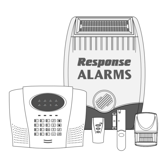
KIT CONTENTS Alarm System should contain the following components. 1 x External Solar Siren 1 x Control Panel 1 x Remote Control 2 x PIR Movement Detectors 2 x Magnetic Contact Detectors Also included: Power Supply Adaptor Installation & Operating Manual Fixing pack Batteries WP1.2-6... -
Page 5: Introduction And Overview
INTRODUCTION AND OVERVIEW SYSTEM ARMING detector on a Delay Armed zone is triggered, an alarm condition will not be triggered until after the Entry/Exit The system has a full ‘Arm’ and a ‘Part-Arm’ mode. period has elapsed. If the system is not disarmed Full ARM will arm all zones while the ‘Part-Arm’... -
Page 6: Tamper Protection
TAMPER PROTECTION SYSTEM HOUSE CODE All system devices (except any Remote Control order to prevent any unauthorised attempt to Units) incorporate Tamper protection features to operate or disarm your system, you must configure protect against unauthorised attempts to interfere your system to accept radio signals only from your with the device. -
Page 7: Planning And Extending Your Wirefree Alarm System
PLANNING AND EXTENDING YOUR WIREFREE ALARM SYSTEM Before attempting to install your Alarm System it is TYPICAL INSTALLATION important to study your security requirements and plan The following example below shows typical property your installation. incorporating the suggested positions for the External Siren, PIR and Magnetic Detectors. -
Page 8: Remote Control Unit
Typical Installation using only detectors supplied: IMPORTANT: All system components must be set to the same Place the 1st Magnetic Contact detector (set on House Code. Zone 1) on the front door. The default User Access Code for the Control 2. -
Page 9: Configuring The Remote Control
CONFIGURING THE REMOTE 1. The Control Panel should be located in a position out CONTROL of sight of potential intruders and in a safe location, but easily accessible for system operation. Remove the rear cover by undoing the small screw on the rear of the Remote Control. -
Page 10: Configuring The Control Panel House Code
Power Supply Cable Route External Tamper N.O. N.C. TAMP Switch Jumper Upper Keyhole Link P51 Fixing Hole Upper Keyhole Fixing Hole -ve Terminal (Black Lead) +ve Terminal (Red Lead) -ve Terminal +ve Terminal (Blue Lead) (Blue Lead) Lower Fixing Hole Reset Jumper Link P1 Power Supply... -
Page 11: Testing The Control Panel & Remote Control
The Panel will beep twice and the Arm and TESTING THE CONTROL PANEL Part-Arm LEDs will illuminate. All Zone, Fire & REMOTE CONTROL and Tamper LEDS will flash. Arm the Panel by pressing the button on This puts the Control Panel into programming mode. the Remote Control. -
Page 12: Passive Infra-Red (Pir) Movement Detectors
PASSIVE INFRA RED (PIR) MOVEMENT DETECTORS PIR detectors are designed to detect movement in a protected area by detecting changes in infra-red radiation levels caused for example when a person Detector Range (metres) moves within or across the devices field of vision. If movement is detected an alarm signal will be generated, (if the system is armed). -
Page 13: Installing And Configuring The Pir Movement Detectors
Note: When the system is Armed, pets should not 5. Configure the House Code for the PIR Detector be allowed into an area protected by a PIR Detector by setting DIP switches 1-8 of SW2 to the same as their movement would trigger the PIR and trigger ON/OFF combination as the House Code DIP an alarm. -
Page 14: Testing The Pir Movement Detectors
Check that the detector PCB is located and set in LED behind the lens will flash. In addition, the Control the correct position to give the detection zone Panel will bleep twice to indicate that the alarm signal pattern required. has been received and the appropriate zone LED which the detector is configured for will illuminate. -
Page 15: Positioning The Magnetic Contact Detectors
occurs the batteries should be replaced as soon as 2. The detector and magnet should be mounted possible. together along the opening edge of the Window/ Door opposite the hinges. Ensure that the parallel Any number of Magnetic Contact Detectors can be gap between the magnet and detector is less than used with the system, providing they are all coded 10mm and that the arrow on the magnet is aligned... -
Page 16: Testing The Magnetic Contact Detectors
If an additional wired contact is connected to the TESTING THE MAGNETIC CONTACT detector then jumper link S2 on the PCB must be DETECTORS removed. Ensure that the system is in Test mode , (see IMPORTANT: If an additional wired contact is not page 17). -
Page 17: Positioning The Solar Siren
generate a full alarm should any unauthorised attempt Shadows cast by neighbouring walls, trees and roof be made to interfere with and remove the siren cover. overhangs should also be avoided. If the Siren is to be mounted below the eaves, it should be positioned a The Siren is powered by a high capacity 6V/1.2Ahr distance of at least twice the width of the eaves rechargeable sealed lead acid battery. -
Page 18: Power-Up Of The Solar Siren
Solar Panel Front cover 7.5 Volt DC locating tabs charging adaptor Receiver input Aerial DIP switch cover Beep Disable Link Tamper switch Siren Disable Link Jamming 6 Volt 1.2Ahr Detection Link rechargeable battery 9 Volt PP3 initial House Code Printed circuit power up battery DIP switches 1-8 board enclosure... -
Page 19: Testing The Solar Siren
Switched Press the anti tamper switch, both indicator LEDs 12Vdc output Hardwired for wired will flash together four times. Siren Siren (300mA max.) 3. Hinge the front cover locating tabs over the top External Tamper Switch Permanent Jumper Link P51 edge of the back plate and carefully push the base 12Vdc power Terminal... -
Page 20: Factory Defaults
Note: After completing all required test functions CONTROL PANEL LED TEST press to leave Test mode and return to Standby. Press Zone LED 4 will illuminate. DETECTOR TEST Before commencing testing please ensure that there is buttons to scroll through no movement in any PIR protected area, all doors/ and illuminate each LED in turn. -
Page 21: Reset Factory Default Conditions
RESET FACTORY DEFAULT To change the setting press CONDITIONS Zone LEDs 1-4 will illuminate. Press Enter the new 4 digit User Access code. As each digit is entered, an illuminated zone LEDs will be ENTER User Access Code turned OFF. This puts the system into Test Mode. -
Page 22: Instant/Delay Zones
INSTANT/DELAY ZONES Press to save the new setting and return ENTER to programming mode, or This defines which zones will operate in conjunction with the systems entry/exit delay period and which Press to return to programming mode zones will instantly trigger an alarm when activated without saving. -
Page 23: Zone Lockout
The zone LEDs corresponding to the zones currently Press active during Part-Arm mode will be illuminated. LEDs The zone 1 LED will illuminate to indicate the current for zones disabled during PART-ARM will be OFF. status of the Entry/Exit warning tone. LED ON Zone enabled in Part-Arm LED ON... -
Page 24: No/Nc Relay Contacts
NO/NC RELAY CONTACTS immediately initiate a Full Alarm condition. This setting controls the operation period for the Fire NO/NC hardwired output relay contacts following an use to provide 24 hour monitoring of any Fire/Smoke alarm condition being initiated. If this is set to ‘ON detectors fitted to the system. -
Page 25: Operating Instructions
OPERATING INSTRUCTIONS When leaving the premises, the system must be alarm duration expires or after 3 minutes, Armed. However, before doing so, check that all whichever occurs first. windows are closed and locked, all protected doors are closed and PIR Movement Detectors are not ARMING THE SYSTEM obstructed. -
Page 26: Personal Attack (Pa) Alarm
PERSONAL ATTACK (PA) ALARM Control Panel: A full Alarm condition can be immediately initiated at With the system in Standby Mode: any time (whether the system is Armed or Disarmed) in Press the event of threat or danger by activating a Personal Attack (PA) switch on either the Remote Control or the ENTER User Access Code... -
Page 27: Battery Monitoring
Press to return to Standby mode. Under normal battery conditions the LED will not illuminate as the Detector is operated, (unless the After approximately 6 seconds the Siren will produce a Detector is in Test Mode with the battery cover single long beep to indicate that it has switched into removed). -
Page 28: Alarm Record
Note: Before removing the Solar Siren from the wall BATTERIES in order to replace the batteries or for any other reason Note: Before removing the battery cover on any device to ensure that the Siren is first switched into Service replace the battery ensure that the siren is switched into Mode to prevent the Siren’s Tamper switch operating Service mode to avoid initiating a Full Alarm condition. -
Page 29: Trouble Shooting
TROUBLE SHOOTING Symptom Recommendation Symptom Recommendation Control Unit not working – Power LED OFF Detection Zone triggered (LED flashing) but or flashing. no alarm is sounding. Mains power failure - check if other electrical Entry/Exit delay still running and not yet expired. circuits are operable. - Page 30 TROUBLE SHOOTING - continued Symptom Recommendation Symptom Recommendation LED on Remote Control not illuminating, or is Magnetic Contact Detector not working. dim when unit is operated. Ensure that magnet is correctly positioned in Ensure battery is fitted with correct polarity. relation to detector and that the gap between magnet and detector is not too large.
-
Page 31: Extending Your Alarm System
If an item develops a fault, the product must be returned to the point of sale with: Proof of purchase. A full description of the fault. All relevant batteries (disconnected). Friedland is a trade mark of Novar ED&S. Friedland, Novar Electrical Devices and Systems. Arnold Centre, Paycocke Road, Basildon, Essex. SS14 3EA. -
Page 32: Component Specification
(Lines open 9.00am to 5.00pm, Jamming Detection Battery Life >1 year Monday to Friday). Battery Indicator Battery Indicator Friedland, Novar Electrical Devices and Systems. Arnold Centre, Paycocke Road, Basildon, Essex SS14 3EA. UK. © Novar ED&S, 2004 45172PL Ed.3...
Need help?
Do you have a question about the SA3 and is the answer not in the manual?
Questions and answers