
Subscribe to Our Youtube Channel
Related Manuals for Response Alarms SA3


Summary of Contents for Response Alarms SA3
-
Page 1: Alarm System
6 Zone Wirefree Alarm System ���� � ���� � ���� � ���� � ���� � ���� � ���� ������ � � � � � � � � � � � � ��� ����� Installation & Operating Manual... -
Page 2: Device Range
FOREWORD SYSTEM SECURITY This system has been designed to both detect intruders All devices in this wirefree Alarm System are designed and act as a strong deterrent to would-be intruders and manufactured to provide a high standard of security when installed correctly. protection and long, reliable service. -
Page 3: Table Of Contents
CONTENTS FACTORY SETTINGS Reset Factory Settings KIT CONTENTS PROGRAMMING INTRODUCTION AND OVERVIEW User Access Code System Arming System House Code Entry/Exit Delay Instant/Delay Zones Zones Entry/Exit Delay Zone Lockout Alarm Duration Tamper Protection Part-Arm Jamming Detection Zone Lockout Battery Monitoring Entry/Exit Warning Tone System House Code Jamming Detection... -
Page 4: Kit Contents
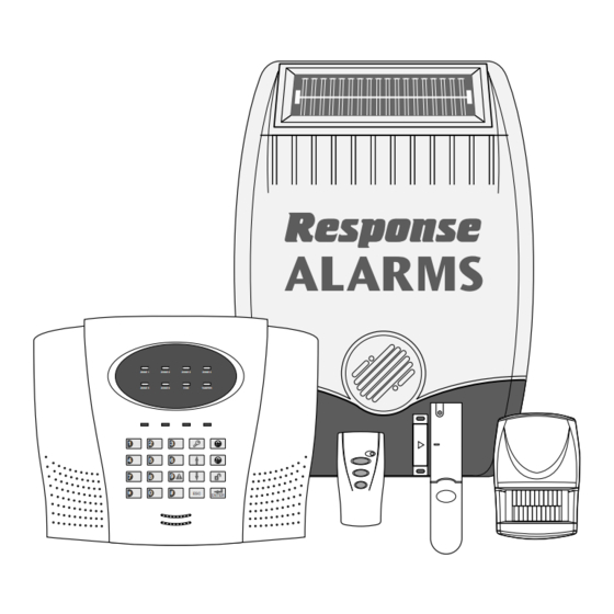
KIT CONTENTS The Alarm System should contain the following devices: 1 x Solar Siren 1 x Control Panel 1 x Remote Control 2 x PIR Movement Detectors 2 x Magnetic Contact Detectors Also included: PIR Movement Detector Power Supply Adaptor Installation &... -
Page 5: Introduction And Overview
INTRODUCTION AND OVERVIEW SYSTEM ARMING ZONES The system has a ‘Full Arm’ and a ‘Part-Arm’ facility. The system incorporates 6 wirefree alarm zones for Full Arm will arm all zones while the ‘Part-Arm’ mode the connection of the detectors used to independently will only arm the zones that are selected and enabled monitor different areas of the property. -
Page 6: Battery Monitoring
possible that it may detect other local radio interference operating legally or illegally on the same frequency. If it is planned to operate the Jamming Detection feature we recommend that the system is monitored for false jamming alarms for at least 2 weeks prior to leaving the Jamming Detection function permanently enabled. -
Page 7: Planning And Extending Your Alarm System
PLANNING AND EXTENDING YOUR ALARM SYSTEM Before attempting to install your Alarm System it is TYPICAL INSTALLATION important to study your security requirements and plan The following example below shows typical property your installation accordingly. incorporating the suggested positions for the External Siren, PIR and Magnetic Contact Detectors. -
Page 8: Remote Control Unit
Typical Installation using only the • Part-Arm is configured to operate with detectors on detectors supplied: zones 1 to 4 only. 1. Place the 1 Magnetic Contact Detector (configured IMPORTANT: All system devices must be set to the on zone 1) on the front door. same House Code. -
Page 9: Configuring The Remote Control
CONTROL PANEL However, under low-battery conditions this LED will continue to flash after the button has been released. When this occurs the battery should be replaced as soon as possible. ��������� ������ ������ ������ ������ CONFIGURING THE REMOTE CONTROL ������ ������... -
Page 10: Installing The Control Panel
INSTALLING THE CONTROL PANEL ������������ ����������� ��������������� ������������� ������������ � �������� ����������� ������������� ����������� ������������ ������������ ������������ ���������� ������������ ������������ ����������� ����������� ������������ ���� ������������ ������� ������������ ����������� Inside View of Control Panel 1. Undo the two cover fixing screws on top of the panel panel. -
Page 11: Configuring The Control Panel House Code
8. Connect battery leads to both back-up batteries and 2. Press refit batteries. This prepares the Control Panel ready to learn the LEFT Battery: Red lead to the Red ( ) battery system House Code. terminal The current House Code setting will be displayed on Blue lead to the Black ( ) battery the status LEDs with an illuminated LED indicating a... -
Page 12: Passive Infra-Red (Pir) Movement Detectors
the beep rate will increase. When the entry/exit delay The PIR Detector also incorporates a sensitivity is completed the beeping will stop and the Arm LED will adjustment feature to compensate for situations stop flashing and be constantly illuminated. where the detector may be triggered by environmental changes, (e.g. -
Page 13: Installing And Configuring The Pir Detectors
The Position of the Circuit Board inside the PIR can 2. Carefully drill out the required mounting holes in the be set to 5 different positions to adjust the range of rear cover using a 3mm drill according to whether the the detection pattern created by the PIR. - Page 14 7. DIP switch 4 of SW3 is used to configure the PIR PCB Position Range Detector for Walk Test, which overrides the 2 minute sleep period and allows the operation of the detector to be checked during installation. Walk Test 11.
-
Page 15: Magnetic Contact Detectors
Note: When the detector is fully installed, i.e. battery Contact Detectors fitted). However additional detectors cover fitted and in operating mode; in order to conserve may be fitted where required to other more vulnerable power and maximise battery life the PIR Detector will doors or windows, (e.g. - Page 16 �������� ����� ��� ���������� ����� �������� ������� ����������� ��������� ����������� ������ �������� �� �������� ������ ���� �� ����� ����������� ������ �� ��� � � � � � � � � � �� �� �� �������� ���� ��� ���� �������� 3. If fixing the detector with screws first remove the �����...
-
Page 17: External Solar Siren
EXTERNAL SOLAR SIREN Testing the Magnetic Contact Detector: 10. With the Control Panel in Test Mode, press The Siren is encapsulated within a tough polycarbonate select Detector Test. housing that also provides full protection against adverse weather conditions. The panel will beep and the zone 1 LED will illuminate. An LED indicator unit is built into the Siren to act as 11. -
Page 18: Installing And Configuring The Solar Siren
INSTALLING AND CONFIGURING THE sufficient daylight in order to maintain the battery SOLAR SIREN charge at acceptable levels. ����� Ensure that the system is in Test Mode (see page 20). �������� 1. Remove the fixing screw from the bottom edge of the ��������... -
Page 19: Power-Up The Solar Siren
POWERING UP THE SIREN 8. Under the cover you will find a series of 9 DIP switches. 1. Connect the 9V PP3 power-up battery to the battery Note: When the Siren is viewed as shown above (Solar clip. Panel at top) the DIP switches are ‘upside down’. Connect the rechargeable battery to the charging 9. -
Page 20: External Connections
EXTERNAL CONNECTIONS The hardwired zone and tamper switches should be volt free and normally closed, with the contacts opening (optional) in order to trigger an alarm. Note: The External Tamper Switch jumper link �������� ��� ������������ P51 should be fitted into the ON position only if the ����������... -
Page 21: Siren Test
SIGNALLING RELAY CONTACTS TEST 2. Press The Control Panel will beep and the ARM LED will Press flash. The internal relay driving the Signaling Relay Contacts (NO/NC) will be activated for a period of approximately 3. Press 5 seconds. The Control Panel will beep and the PART-ARM LED will flash. -
Page 22: Factory Settings
FACTORY SETTINGS PROGRAMMING INSTRUCTIONS User Access Code: 1 2 3 4 With the system in Standby (i.e. with the Power LED Alarm Duration: 3 minutes ON). Hardwired Siren: Equal to Alarm Duration Note: To get to Standby Mode simply press Zone Operating Mode: Intruder (all zones) repeatedly until only the POWER LED is illuminated. -
Page 23: Instant/Delay Zones
For example, a house code of 1101 0011, will be To change the setting: indicated as shown below: Press the button corresponding to the zone number to be changed. The zone’s status (delay or instant) will switch to the opposite state each ����... -
Page 24: Part-Arm
ZONE LOCKOUT Default setting: 3 minutes This feature if enabled, will only allow a single zone Press to trigger an alarm up to 3 times before the system is The zone LED corresponding to the current setting will disarmed. However, if this feature is disabled there is illuminate. -
Page 25: Jamming Detection
JAMMING DETECTION To change the setting: Press the key corresponding to the required activation This allows the Control Panel’s anti-jamming detection period, the corresponding zone LED will illuminate as facility to be switched ON or OFF as required. If the setting is changed. enabled, the system will continuously scan for radio jamming signals on the system’s operating frequency Press... -
Page 26: Operating Instructions
OPERATING The zone LED corresponding to the current operating mode will illuminate. INSTRUCTIONS Zone 1 LED Personal Attack (PA) When leaving the premises, the system must be Zone 2 LED Intruder Armed. However, before doing so, check that all Zone 3 LED 24 Hour Intruder windows are closed and locked, all protected doors are closed and PIR Detectors are not obstructed. -
Page 27: Arming The System
ARMING THE SYSTEM The alarm will continue either for the alarm duration after which the system will automatically reset or until The system can be set in FULL ARM mode using either the system is disarmed. the Remote Control or the Control Panel as follows: DEVICE TAMPER a. -
Page 28: Siren Operating Mode
The Siren will produce 2 short beeps as the button is In addition, if any PIR or Magnetic Contact Detector pressed followed by a single long beep approximately has a low battery status it will be indicated on the ‘LOW 6 seconds later to indicate that it has switched into BAT’... -
Page 29: Maintenance
MAINTENANCE CONTROL PANEL The rechargeable batteries have a typical life in excess Your Alarm System requires very little maintenance. of 3 to 4 years and need no maintenance during this However, a few simple tasks will ensure its continued period, provided they are kept charged. The batteries reliability and operation. -
Page 30: Alarm Record
ALARM RECORD Complete the following information during installation for future reference, when adding to your system and to assist trouble shooting. Zone Settings Zone Instant/ Zone Detector Type(s) Location Operating Part-Arm Delay Mode You may make a note of your User Access Codes and Installer Access Code below. User Access Code System House Code Use the above diagram to record your House Code e.g. -
Page 31: Troubleshooting
TROUBLESHOOTING Symptom / Recommendation Control Unit not working – Power LED OFF or flashing. Siren not responding to Control Panel. Mains power failure - check if other electrical circuits are Ensure ‘House Code’ is correctly set to the same code operable. - Page 32 LED on Magnetic Contact Detector illuminating when Ensure DIP switches 1, 2 and 3 of SW3 are correctly door or window is opened set according to the required zone. Ensure that detector is mounted the correct way up, (i.e. Low battery - replace batteries. with detection window at the bottom).
-
Page 33: Accessories
If an item develops a fault, the product must be returned to the point of sale with: 1. Proof of purchase. 2. A full description of the fault. 3. All relevant batteries (disconnected). Friedland is a trademark of Novar ED&S. -
Page 36: Component Specification
Monday to Friday) • Low Battery Indicator Novar Electrical Devices and Systems are Quality Assurance Registered to BS EN ISO9001 : 2000, by Asta. Friedland, Novar Electrical Devices and Systems. The Arnold Centre, Paycocke Road, Basildon, Essex SS14 3EA. UK. 45172PL Ed.4...
Need help?
Do you have a question about the SA3 and is the answer not in the manual?
Questions and answers