Table of Contents
Advertisement
Quick Links
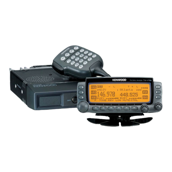
144/440MHz FM DUAL BANDER
TM-V708A
SERVICE MANUAL
Panel (DISPLAY)
(A62-0775-03)
Button knob
(K29-5400-11)
Knob (ENC)
(K29-5381-03)
Cabinet (UPPER)
(A01-2122-23)
Panel (MAIN UNIT)
(A62-1122-03)
CIRCUIT DESCRIPTION ......................................... 2
SEMICONDUCTOR DATA ................................... 14
COMPONENTS DESCRIPTION ........................... 17
TERMINAL FUNCTION ........................................ 19
PARTS LIST .......................................................... 20
EXPLODED VIEW ................................................. 31
PACKING .............................................................. 32
ADJUSTMENT ..................................................... 33
Microphone
(T91-0636-05)
CONTENTS
TX-RX UNIT (X57-5860-12) ............................ 47
PANEL UNIT (X54-3290-00) ........................... 53
SCHEMATIC DIAGRAM ....................................... 57
BLOCK DIAGRAM ................................................ 67
INTERCONNECTION DIAGRAM ......................... 69
LEVEL DIAGRAM ................................................. 70
OPTION (PG-4X) .................................................. 71
SPECIFICATIONS .............................. BACK COVER
©
2004-11 PRINTED IN JAPAN
B51-8704-00 (S) 237
Button knob
(K29-5400-11)
Knob (SQL)
(K29-5223-03)
Knob (VOL)
(K29-5222-03)
Advertisement
Table of Contents

Related Manuals for Kenwood TM-V708A


Summary of Contents for Kenwood TM-V708A
-
Page 1: Table Of Contents
144/440MHz FM DUAL BANDER TM-V708A SERVICE MANUAL © 2004-11 PRINTED IN JAPAN B51-8704-00 (S) 237 Microphone (T91-0636-05) Panel (DISPLAY) (A62-0775-03) Button knob (K29-5400-11) Button knob (K29-5400-11) Knob (SQL) (K29-5223-03) Knob (ENC) (K29-5381-03) Cabinet (UPPER) Knob (VOL) (A01-2122-23) (K29-5222-03) Panel (MAIN UNIT) -
Page 2: Circuit Description
TM-V708A CIRCUIT DESCRIPTION Outline List of Destination This device is a dual-band 144/440MHz FM car transceiver Guarantee frequency range (MHz) Output Power (W) Model & planned and designed for amateur radio communications and Destination has the following features. TM-V708A 144-148 438-450 1. -
Page 3: Circuit Description
TM-V708A CIRCUIT DESCRIPTION 1. Frequency configuration The TM-V708A has an individual VCO and PLL unit for The UHF VCO is used for the following functions: both VHF and UHF bands. Using these separate VCO and (i) UHF transmission PLL circuit, it can receive 2 separate bands at the same time. -
Page 4: Receiver System
TM-V708A CIRCUIT DESCRIPTION 2. Receiver system 2-1. Main VHF Receiver The incoming signal from the antenna passes through a the signal is converted by the first local oscillator (Upper filter circuit and goes to the RF amplifier (Q205). The heterodyne) to generate a 38.85MHz first IF signal. The signal... - Page 5 TM-V708A CIRCUIT DESCRIPTION 2-3. Sub VHF Receiver The signal distributed from the RF amplifier (Q205) at the frequency to generate a 45.05MHz first IF signal. The signal main VHF receiver circuit passes through a filter circuit. Then passes through the MCF (XF400). Then it is amplified by the it enters the RF amplifier (Q507).
-
Page 6: Circuit Description
TM-V708A CIRCUIT DESCRIPTION Item Rating Item Rating Center Frequency 38.85MHz Center Frequency 45.05MHz ±7.5kHz or more at 3dB ±7.5kHz or more at 3dB Pass band width Pass band width ±25kHz or less at 40dB ±22kHz or less at 25dB Attenuation band width... - Page 7 TM-V708A CIRCUIT DESCRIPTION RAV and RAU is de-emphasized audio signal RDV and RDU is not de-emphasized. RAV from IF RDV from IF RAU from IF RDU from IF IC702 BEEP sound from CPU VS-3 vocal sound of option DTMF/1750 signal from CPU DTMF sound from MIC.
- Page 8 TM-V708A CIRCUIT DESCRIPTION 3. Transmitter system 3-1. Modulation Circuit The audio modulation input from the microphone is UHF VCOs as a modulation signal. The TONE/CTCSS/DCS amplified by IC801. The DTMF signal and 1750Hz tone signal signal generated by the CPU is fed to IC802 in the same way generated by the CPU are also mixed by IC801.
- Page 9 TM-V708A CIRCUIT DESCRIPTION 3-3. APC circuit The Automatic transmission Power Control (APC) circuit the reference voltage output from the CPU. The output signal has a differential amplifier (IC200) that compares the DC is amplified by Q209 and Q208 and fed to the power module voltage generated by detecting part of the transmission to keep transmission output constant.
- Page 10 TM-V708A CIRCUIT DESCRIPTION 4-2. Phase comparator 5-2. Voltage detection processing Part of the VHF VCO output is amplified by Q3 and goes to The CPU (IC604) monitors and process various voltage VHF PLL IC. Also, a part of the UHF VCO output is amplified status at IC604 A/D ports.
- Page 11 However, with when a key is ON operates the corresponding function. Also, the TM-V708A, the power ON/OFF switch function can be the key input interrupt circuit is for switching the power ON/ registered to the PF key on the microphone.
- Page 12 TM-V708A CIRCUIT DESCRIPTION 7. Data Terminal and Peripheral Circuits J700 (data terminal) is the data communications terminal Different types of modulation, such as GMSK and G3RUH, on the front. It handles transmission control, data input/ are distinguished by the type of band limiting filter.
- Page 13 TM-V708A CIRCUIT DESCRIPTION 7-2. Reception signals 8-3. Display circuit PR9 is the 9600bps data communications reception The TM- V708A display section is a 188x54-dot full-dot output. It outputs the FM detection circuit output (RD signals) matrix LCD controlled by two LCD. As shown is Figure 17, through a buffer amp (Q700).
-
Page 14: Semiconductor Data
TM-V708A SEMICONDUCTOR DATA 30622M8759GP (PANEL UNIT CPU : IC4) Active Active Port Name I/O Function Port Name I/O Function Level Level KYCALL [CALL] key input Not used (VCC) KYVFO [VFO] key input 37-41 Not used KYMR [MR] key input Read signal... - Page 15 TM-V708A SEMICONDUCTOR DATA 78F4218AGJZXA (TX-RX UNIT CPU : IC604) Pin No. Port Name Function Active Level UPLLEN U PLL Enable output MB1511PFV VPLLEN V PLL Enable output MB1511PFV PSW1 Transceiver main power switch (SBSW) H:ON PSW2 Transceiver main power switch (CPU)
- Page 16 TM-V708A SEMICONDUCTOR DATA Pin No. Port Name Function Active Level − 54-58 Not used − Not used 60-63 SIM0-3 Destination judgment bit 0-3 Destination, channel display mode [PTT] key input L:Push down PEPTR Common clock (XSW, 2099, E2P, DAC, VPLL, UPLL)
-
Page 17: Components Description
TM-V708A COMPONENTS DESCRIPTION TX-RX UNIT (X57-5860-12) Operation/Condition/ Operation/Condition/ Ref No. Application/Function Ref No. Application/Function Compatibility Compatibility PLL IC VHF PLL Q111 AGC amp Q112 IF amp Power Module Q113 Power Module Q200 1st Mixer IC100 IF LC A band Q201... - Page 18 TM-V708A COMPONENTS DESCRIPTION Operation/Condition/ Operation/Condition/ Ref No. Application/Function Ref No. Application/Function Compatibility Compatibility Q905 Power switch R8V, R8U D305 RF switch UHF LO Q906 Power switch RM43, RM80 D306 RF switch UHF TX Q907 Power switch RS14, RM30 D307 RF switch...
-
Page 19: Terminal Function
TM-V708A TERMINAL FUNCTION TX-RX UNIT (X57-5860-12) PANEL UNIT (X54-3290-00) CN No. Pin No. Name Function CN No. Pin No. Name Function CN601 VS-3 clock LCD driver data VS-3 data LCD driver data VS-3 chip select LCD driver data VS-3 reset... -
Page 20: Parts List
E: Europe Les articles non mentionnes dans le Parts No. ne sont pas fournis. Y: AAFES (Europe) X: Australia M: Other Areas Teile ohne Parts No. werden nicht geliefert. TM-V708A (Y51-4570-12) PANEL UNIT (X54-3290-00) Ref. No. Address Parts No. Description Destination Ref. - Page 21 TM-V708A PARTS LIST PANEL UNIT (X54-3290-00) TX-RX UNIT (X57-5860-12) Ref. No. Address Parts No. Description Destination Ref. No. Address Parts No. Description Destination parts parts R27 -29 RK73GB1J102J CHIP R 1.0K J 1/16W CK73GB1H102K CHIP C 1000PF K R30 -32...
- Page 22 TM-V708A PARTS LIST TX-RX UNIT (X57-5860-12) Ref. No. Address Parts No. Description Destination Ref. No. Address Parts No. Description Destination parts parts C142 CK73FB1C105K CHIP C 1.0UF C304 CC73GCH1H060D CHIP C 6.0PF C144,145 CK73GB1C104K CHIP C 0.10UF K C305 CC73GCH1H050C CHIP C 5.0PF...
- Page 23 TM-V708A PARTS LIST TX-RX UNIT (X57-5860-12) Ref. No. Address Parts No. Description Destination Ref. No. Address Parts No. Description Destination parts parts C378 CC73GCH1H0R5B CHIP C 0.5PF C534 CC73GCH1H050C CHIP C 5.0PF C379 CC73GCH1H020B CHIP C 2.0PF C535 CC73GCH1H030B CHIP C 3.0PF...
- Page 24 TM-V708A PARTS LIST TX-RX UNIT (X57-5860-12) Ref. No. Address Parts No. Description Destination Ref. No. Address Parts No. Description Destination parts parts C736,737 CK73FB1C105K CHIP C 1.0UF C903 CK73GB1H103K CHIP C 0.010UF K C738,739 CC73GCH1H101J CHIP C 100PF C904 CK73GB1H102K...
- Page 25 TM-V708A PARTS LIST TX-RX UNIT (X57-5860-12) Ref. No. Address Parts No. Description Destination Ref. No. Address Parts No. Description Destination parts parts L205,206 L40-5675-54 SMALL FIXED INDUCTOR(56NH) L77-1831-05 CRYSTAL RESONATOR(12.8MHZ) L207 L34-4506-15 COIL X300 L77-1831-05 CRYSTAL RESONATOR(12.8MHZ) L209 L34-4506-15 COIL...
- Page 26 TM-V708A PARTS LIST TX-RX UNIT (X57-5860-12) Ref. No. Address Parts No. Description Destination Ref. No. Address Parts No. Description Destination parts parts R215 RK73GB1J184J CHIP R 180K J 1/16W R109 R92-1252-05 CHIP R 0 OHM J 1/16W R216 RK73GB1J471J CHIP R...
- Page 27 TM-V708A PARTS LIST TX-RX UNIT (X57-5860-12) Ref. No. Address Parts No. Description Destination Ref. No. Address Parts No. Description Destination parts parts R330 RK73GB1J470J CHIP R J 1/16W R423 R92-1252-05 CHIP R 0 OHM J 1/16W R331 RK73GB1J102J CHIP R 1.0K...
- Page 28 TM-V708A PARTS LIST TX-RX UNIT (X57-5860-12) Ref. No. Address Parts No. Description Destination Ref. No. Address Parts No. Description Destination parts parts R646 RK73GB1J223J CHIP R J 1/16W R807 RK73GB1J102J CHIP R 1.0K J 1/16W R647 RK73GB1J104J CHIP R 100K...
- Page 29 TM-V708A PARTS LIST TX-RX UNIT (X57-5860-12) Ref. No. Address Parts No. Description Destination Ref. No. Address Parts No. Description Destination parts parts R887 R92-1252-05 CHIP R 0 OHM J 1/16W D503 DAN235E DIODE R889 R92-1252-05 CHIP R 0 OHM J 1/16W...
- Page 30 TM-V708A PARTS LIST TX-RX UNIT (X57-5860-12) Ref. No. Address Parts No. Description Destination Ref. No. Address Parts No. Description Destination parts parts Q104 DTA114EE DIGITAL TRANSISTOR Q105-108 2SC4617(R) TRANSISTOR Q110,111 2SC4617(R) TRANSISTOR Q112 2SC5108(Y) TRANSISTOR Q113 2SC4617(R) TRANSISTOR Q200,201 2SK302(GR)
-
Page 31: Exploded View
TM-V708A EXPLODED VIEW : N14-0569-04 : N33-2606-45 34(Fuse) : N67-3008-46 : N80-2010-45 : N80-2610-45 : N83-2608-46 : N87-2606-46 (SP) 700 (Chassis) TX-RX UNIT(X57) PANEL UNIT (X54 A/3) (X54 B/3) (X54 C/3) Parts with the exploded numbers larger than 700 are not supplied. -
Page 32: Packing
TM-V708A PACKING 20.Instruction Manual (B62-1834-00) 19.Warranty card (B46-0469-20) 55.Packing Fixture (H12-3075-03) 64.Foot (J02-0488-04) 69.Bracket (J29-0663-13) 48.Cushion 65.Holder (Bracket) 59.Protection Bag (J19-1526-04) (G13-1757-04) (H25-0103-04) 76.Screw set (N99-0382-05) 77.Screw set (N99-2014-05) 58.Protection Bag 66.Bracket (Main unit) (H25-0085-04) (J29-0628-23) 34.Fuse (15A) 80.Microphone (F51-0017-15) (T91-0636-05) 25.Moduler Cable... -
Page 33: Adjustment
TM-V708A ADJUSTMENT Measuring Equipment for Adjustment Preparation • Set the controls and switches to the positions listed below 1. Digital voltmeter (D.V.M) unless otherwise specified. Input impedance: High VOL control Fully counterclockwise 2. RF valve voltmeter (RF V.M) Input impedance: 1MΩ or more, 2 pF or less Voltage... - Page 34 TM-V708A ADJUSTMENT Adjustment Service Jig Data terminal short plug (W05-0611-00) Service jigs usage 6(SQC) 5(PR1) 3(PKS) 4(PR9) E(GND) 2(DE) 1(PKD) Pin assignment seen from direction B Short plug Terminals 3 and 6 are short circuited. [Reference] 3 PKS (SEND switch for DATA terminal) Connect PTT output.
- Page 35 TM-V708A ADJUSTMENT Parts layout Front panel CALL Encoder (BAND B) TONE REV LOW MUTE CTRL (BAND A) VOL/BAND SEL VOL/BAND SEL (BAND A) (BAND B) Rear panel Adjustment parts layout • TX-RX UNIT (Foil side view) (Unit under) • Adjustment parts No.
- Page 36 TM-V708A ADJUSTMENT B. S meter (value set for each band) Adjustment mode 1. Press the [ ] and [ ] keys to display “S METER”. The current S meter input value is displayed on the • This is the adjustment mode for making adjustments or screen and adjustment can be performed.
- Page 37 TM-V708A ADJUSTMENT F. Tone deviation 6. Upper limit frequency transmission output setting. (1)Set the upper limit frequency and press the (values set independently for 144MHz and 430MHz) microphone PTT button to enter transmit mode. 1. Press the [ ] and [ ] keys to display “TONE DEV”.
- Page 38 TM-V708A ADJUSTMENT Common section Measurement Adjustment Specifications/ Item Condition Test- Unit Terminal Unit Parts Method Remarks equipment 1. Setting 1) Power voltage:13.8V 2) Band A, Band B VOL, SQL knob:MIN 2. Reset PARTIAL OR FULL RESET? 1. Press [MNU] to enter Menu mode.
- Page 39 TM-V708A ADJUSTMENT Receiver section Measurement Adjustment Specifications/ Item Condition Test- Unit Terminal Unit Parts Method Remarks equipment 1. AF distortion 1) Band A Rear TX-RX L200 SINAD adjust FREQ.:146.250MHz Oscilloscope panel EXT.SP L102 SSG:0.178µV (-122dBm) AF V.M AF output:0.63V/8Ω Distortion...
- Page 40 TM-V708A ADJUSTMENT Receiver section Measurement Adjustment Specifications/ Item Condition Test- Unit Terminal Unit Parts Method Remarks equipment 4. Squelch 4) FREQ.:146.350MHz Rear Display [SET] key Write write SSG:0.20µV (-121dBm) panel EXT.SP SSG MOD:60% 1kHz 5) FREQ.:127.100MHz SSG:0.20µV (-121dBm) SSG MOD:60% 1kHz 6) FREQ.:223.100MHz...
- Page 41 TM-V708A ADJUSTMENT Receiver section Measurement Adjustment Specifications/ Item Condition Test- Unit Terminal Unit Parts Method Remarks equipment 5. Squelch 5) SSG:0.112µV Rear Display Check Squelch open. check (-126dBm) Oscilloscope panel EXT.SP BUSY lights on. 6) Squelch knob: AF output disappear.
- Page 42 TM-V708A ADJUSTMENT Receiver section Measurement Adjustment Specifications/ Item Condition Test- Unit Terminal Unit Parts Method Remarks equipment 6. S-meter 4) FREQ.:146.350MHz Rear Display [S1] key Write One Segment in write SSG MOD:60%,1kHz panel S-meter lights. SSG:0.28µV (-118dBm) [S7] key All segments in SSG:39.8µV (-75dBm)
- Page 43 TM-V708A ADJUSTMENT Receiver section Measurement Adjustment Specifications/ Item Condition Test- Unit Terminal Unit Parts Method Remarks equipment 6. S-meter Band B Rear Display [S1] key Write One Segment in write 11)FREQ.:444.350MHz panel S-meter lights. SSG DEV:3kHz MOD:1kHz SSG:0.28µV (-118dBm) [S7] key All segments in SSG:3.54µV (-96dBm)
- Page 44 TM-V708A ADJUSTMENT Transmission section Measurement Adjustment Specifications/ Item Condition Test- Unit Terminal Unit Parts Method Remarks equipment 1. Transmission 1) Band A f. counter Rear TX-RX 146.000 Not Warm up the set. ±100Hz frequency FREQ.:146.000MHz Power meter panel adjust Transmission...
- Page 45 TM-V708A ADJUSTMENT Transmission section Measurement Adjustment Specifications/ Item Condition Test- Unit Terminal Unit Parts Method Remarks equipment 2-2.POWER 5) FREQ.:438.000MHz Power Rear Check 28 ~ 42W write or check FREQ.:449.975MHz meter panel Band B POWER:HI Ammeter Transmission 6) POWER:MID 10 ~ 14W...
- Page 46 TM-V708A ADJUSTMENT Transmission section Measurement Adjustment Specifications/ Item Condition Test- Unit Terminal Unit Parts Method Remarks equipment ±0.5 ~ 1.3kHz 5. TONE DEV 4) FREQ.:445.100MHz Power meter Rear Check write or check TONE:88.5Hz Linear panel Band B Transmission detector Oscilloscope ±0.8kHz±0.15kHz...
-
Page 47: Pc Board
TM-V708A PC BOARD TX-RX UNIT Component side TX-RX UNIT (X57-5860-12) Component side view (J72-0653-11) Ref.NO. Address DTA114EE NJM2904V R922 R917 IC806 Q911 DTC114EE C919 C926 R916 Q912 J801 C850 C858 Q910 IC904 C854 IC101 C929 IC301 C916 R919 C857 C920... - Page 48 TM-V708A PC BOARD TX-RX UNIT TX-RX UNIT (X57-5860-12) Foil side view (J72-0653-11) Foil side 2SB1132 PST9130NR Ref.NO. Address Ref.NO. Address 2SC2954 R865 2SC3357 IC100 Q903 C848 C925 CN601 IC200 Q904 Q804 C864 R870 IC300 Q905 R890 R875 R872 C855 R892...
- Page 49 TM-V708A PC BOARD TX-RX UNIT Component side + Foil side TX-RX UNIT (X57-5860-12) Component side + Foil side view (J72-0653-11) Ref.NO. Address Ref.NO. Address Q203 R865 Q204 C848 R922 R917 IC806 C925 CN601 Q911 Q205 R916 C919 C926 Q804 C864...
-
Page 50: Panel Unit (X54-3290-00)
TM-V708A PC BOARD PANEL UNIT (X54-3290-00) Component side view (J72-0707-12) PANEL UNIT Component side Ref.NO. Address X54-3290-00 (A / 3) J72-0707-12 CP10 CP12 CP11 CP13 2SA1162 DTC143EKA L78LR05B-FA DA221 30622M8759GP AT29C020-90TI TC4SB1F Component side Layer 1 Layer 2 Foil side... - Page 51 TM-V708A PC BOARD PANEL UNIT (X54-3290-00) Foil side view (J72-0707-12) PANEL UNIT Foil side Ref.NO. Address X54-3290-00 (A / 3) X54-3290-00 (A / 3) J72-0707-12 J72-0707-12 CP10 CP12 CP11 CP13 2SA1162 DTC143EKA L78LR05B-FA DA221 30622M8759GP AT29C020-90TI TC4SB1F Component side Layer 1...
-
Page 52: Schematic Diagram
TM-V708A SCHEMATIC DIAGRAM Note : The components marked with a dot ( ● ) are parts of layer1. - Page 53 TM-V708A SCHEMATIC DIAGRAM Note : The components marked with a dot ( ● ) are parts of layer1.
-
Page 54: Schematic Diagram
TM-V708A SCHEMATIC DIAGRAM ● Note : The components marked with a dot ( ) are parts of layer1. -
Page 55: Block Diagram
TM-V708A TM-V708A BLOCK DIAGRAM MA4PH633 MA4PH633 78F4218AGJZXA X57-5860-12... -
Page 56: Interconnection Diagram
TM-V708A INTERCONNECTION DIAGRAM... -
Page 57: Level Diagram
TM-V708A LEVEL DIAGRAM Transmitter Section MODULE 1.6V 2.5mV 0.63V 0.53V 80mV 0dBm +10dBm +19dBm +25dBm IC801 Q801 Q802 IC804 1200bps MODULE 80mV -2dBm -1dBm +14dBm +21dBm +26dBm 9600bps (data communications) Q304 Q307 Q309 Q310 IC302 Note1: Set the AG so that the microphone socket input is 3kHz Note2: The transmit frequency is 145.0 or 435.0MHz. -
Page 58: Option (Pg-4X)
TM-V708A OPTION PG-4X (Extension cable kit) PG-4X MAIN PARTS LIST Ref. New Parts No. Q'ty Parts Name No Parts E30-3199-15 DC CORD (6m) ∗ E30-7521-05 MODULAR CABLE (4m:MIC) E30-3395-05 MODULAR CABLE (4m:PANEL) E30-3399-05 TRUNK CABLE (4m:SP) E58-0472-05 MODULAR JACK (6 PIN) -
Page 59: Specifications
KENWOOD ELECTRONICS SINGAPORE PTE LTD. 13, Boulevard Ney, 75018 Paris, France 1 Ang Mo Kio Street 63, Singapore 569110 KENWOOD ELECTRONICS U.K. LIMITED KENWOOD House, Dwight Road, Watford, Herts., WD18 9EB, United Kingdom KENWOOD ELECTRONICS EUROPE B.V. Amsterdamseweg 37, 1422 AC Uithoorn, The Netherlands...
Need help?
Do you have a question about the TM-V708A and is the answer not in the manual?
Questions and answers