
Related Manuals for Kenwood TM-481A


Summary of Contents for Kenwood TM-481A
-
Page 1: Instruction Manual
TM-281A/ TM-481A 144 MHz FM TRANSCEIVER 430 MHz FM TRANSCEIVER INSTRUCTION MANUAL 144 MHz FM 调频对讲机 430 MHz FM 调频对讲机 使用说明书 © B62-2348-20 (M,M3) 09 08 07 06 05 04 03 02... - Page 2 INSTRUCTION MANUAL 144 MHz FM TRANSCEIVER TM-281A 430 MHz FM TRANSCEIVER TM-481A...
- Page 3 The market code is printed on the barcode label of the transceiver is no exception. As you learn how to use this carton box. transceiver, you will find that Kenwood is pursuing “user Refer to the product specifications {pages 69, 70} for friendliness”. For example, each time you change the information on the available operating frequencies within Menu No.
- Page 4 • If an abnormal odor or smoke is detected coming from the transceiver, turn OFF the power immediately. Contact a Kenwood service station or your dealer. • This transceiver is designed for a 13.8 V power source.
-
Page 5: Table Of Contents
CONTENTS SUPPLIED ACCESSORIES ........1 VFO M ............15 MHz M ............16 WRITING CONVENTIONS FOLLOWED IN THIS MANUAL ............1 ........16 IRECT REQUENCY NTRY CHAPTER PREPARATION CHAPTER MENU SETUP MOBILE INSTALLATION .......... 2 WHAT IS A MENU? ..........18 MENU ACCESS ............ - Page 6 CTCSS F ......45 ........30 ELECTING A REQUENCY SING THE UNING ONTROL CTCSS F ID S ........ 45 ......31 REQUENCY SING THE ICROPHONE EYPAD DCS ................. 46 CLEARING A MEMORY CHANNEL ....... 31 DCS C ........46 NAMING A MEMORY CHANNEL ......32 ELECTING A DCS C ID S...
- Page 7 LOCK FUNCTION ........... 56 TUNE ENABLE ............56 MICROPHONE PF KEYS (K ) ..57 EYPAD ODELS NARROW BAND FM OPERATION ......58 POWER-ON MESSAGE ......... 58 PROGRAMMABLE VFO ......... 59 TIME-OUT TIMER ........... 60 CHAPTER MICROPHONE CONTROL MIC LOCK ............... 62 CHAPTER OPTIONAL ACCESSORIES CHAPTER...
-
Page 8: Supplied Accessories
SUPPLIED ACCESSORIES WRITING CONVENTIONS FOLLOWED IN THIS MANUAL After carefully unpacking the transceiver, identify the The writing conventions described below have been items listed in the table below. We recommend you keep followed to simplify instructions and avoid unnecessary the box and packaging for shipping. repetition. -
Page 9: Chapter 1 Preparation
PREPARATION 2 Position the transceiver, then insert and tighten MOBILE INSTALLATION the supplied hexagon SEMS screws (4) and flat To install the transceiver, select a safe, convenient washers (4). location inside your vehicle that minimizes danger to your • Double check that all hardware is tightened to prevent passengers and yourself while the vehicle is in motion. -
Page 10: Dc Power Cable Connection
4 Confirm the correct polarity of the connections, then DC POWER CABLE CONNECTION attach the power cable to the battery terminals; red connects to the positive (+) terminal and black connects to the negative (–) terminal. Locate the power input connector as close to the transceiver as •... -
Page 11: Fixed Station Operation
2 Connect the transceiver’s DC power connector to the IXED TATION PERATION connector on the DC power cable. In order to use this transceiver for fixed station operation, • Press the connectors firmly together until the locking tab you will need a separate 13.8 V DC power supply (not clicks. -
Page 12: Replacing Fuses
If newly installed fuses continue to blow, disconnect the type of antenna and its correct installation. The the power cable and contact your authorized Kenwood transceiver can give excellent results if the antenna dealer or an authorized Kenwood service center for system and its installation are given careful attention. -
Page 13: Accessory Connections
ACCESSORY CONNECTIONS ICROPHONE For voice communications, connect a 600 Ω microphone XTERNAL PEAKER equipped with an 8-pin modular plug into the modular socket on the front of the main unit. Press firmly on the If you plan to use an external speaker, choose a speaker plug until the locking tab clicks. -
Page 14: Pc Connection
To utilize the optional MCP-1A software, you must first connect the transceiver to your PC using an optional Programming Cable (via the microphone jack). The MCP-1A is free downloadable software available from Kenwood at the following URL: http://www.kenwood.com/i/products/info/amateur/software_download.html Note: Ask your dealer about purchasing a Programming Cable. -
Page 15: Chapter 2 Your First Qso
YOUR FIRST QSO 1 Press [ ] (Power) briefly to switch the transceiver power ON. Are you ready to give your transceiver a quick try? Reading this section should get your voice on the • A high pitched double beep sounds and a Power-on message appears momentarily. -
Page 16: Chapter 3 Getting Acquainted
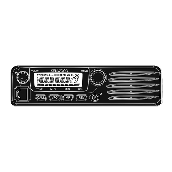
GETTING ACQUAINTED Press [F] then press [MENU] to enter Menu Mode FRONT PANEL {page 18}. Note: This section describes only the main functions of the front Turn to select: panel controls. Explanations for functions not described here are provided in the appropriate sections of this instruction manual. •... -
Page 17: Display
In MR Mode, press [F] then press [VFO] to transfer DISPLAY the contents of the selected Memory Channel to the VFO {page 33}. t MR key Press to enter Memory Recall Mode {page 30}. In this mode, you can change memory channels using the Tuning control or Mic [UP]/[DWN]. - Page 18 Appears when the Automatic Simplex Check (ASC) Appears when the Memory Channel Lockout function is function is activated {page 26}. ON {page 42}. Appears when the Priority Scan function is activated Shows the strength of transmitted {page 15} and received {page 42}.
-
Page 19: Rear Panel
REAR PANEL MICROPHONE DTMF Microphone Microphone (KMC-30) q Antenna connector q PTT (Push-to-Talk) switch Connect an external antenna {page 5} here. When Press and hold to transmit. Release to receive. making test transmissions, connect a dummy load in place of the antenna. The antenna system or load w DWN/ should have an impedance of 50 Ω. -
Page 20: Mic Keypad Direct Entry
r CALL/A key EYPAD IRECT NTRY Identical to the front panel CALL key. This key can The microphone keypad (keypad models only) allows you be reprogrammed if desired {page 57}. Press and hold to make various entries depending on which mode the Mic [PTT], then press [CALL/A] to transmit A. -
Page 21: Chapter 4 Operating Basics
OPERATING BASICS SWITCHING THE POWER ON/OFF ADJUSTING THE SQUELCH 1 Press [ ] (Power) to switch the transceiver power The purpose of Squelch is to mute the speaker when no signals are present. With the squelch level correctly set, you will hear sound only while actually receiving signals. •... -
Page 22: Transmitting
2 Press [MENU] and turn the Tuning control to select “H” (high; default) or “L” (low) power. TRANSMITTING 3 Press [MENU] to store the setting or any other key to 1 To transmit, hold the microphone approximately 5 cm cancel. (2 inches) from your mouth, then press and hold Mic [PTT] and speak into the microphone in your normal 4 Press any key other than [MENU] to exit Menu Mode. -
Page 23: Mhz Mode
IRECT REQUENCY NTRY If the desired operating frequency is far away from the In addition to turning the Tuning control or pressing Mic current frequency, it is quicker to use the MHz Tuning [UP]/[DWN], there is another way to select the frequency. Mode. - Page 24 Note: If the entered frequency does not match the current frequency Example 1 step size, the frequency is automatically rounded down to the next To enter 145.750 MHz: available frequency. When the desired frequency cannot be entered exactly, confirm the frequency step size {page 54}. Key in Display [Enter]...
-
Page 25: Chapter 5 Menu Setup
MENU SETUP 2 Turn the Tuning control to select your desired Menu. WHAT IS A MENU? • As you change the Menu No., a brief explanation of each Many functions on this transceiver are selected or menu appears along with its current parameter. configured via a software-controlled Menu rather than through the physical controls of the transceiver. -
Page 26: Menu Function List
Page 2.5( )/5 / 6.25/ 10/ 12.5/ 15/ TM-281A Only TM-281A: 12.5 kHz Frequency step size 20/ 25/ 30/ 50/ 100 kHz TM-481A: 25 kHz Tone frequency 67.0 ~ 254.1 kHz 88.5 CTCSS frequency 67.0 ~ 254.1 kHz 88.5 DCS code... - Page 27 On the Menu Function Selections Default display Page Varies (see CALL key CALL/ 1750 25,35 reference page) 1750 Hz tone TX hold ON/ OFF Time-out Timer 3/ 5/ 10 min. Busy Channel Lockout ON/ OFF P.ON.MSG Power-on message 6 character −...
- Page 28 On the Menu Function Selections Default display Page MONI/ ENTER/ 1750/ VFO/ MR/ CALL/ Microphone programmable MHZ/ REV/ SQL/ M--V/ M.IN/ C.IN/ function key MENU/ SHIFT/ LOW/ BRIGHT/ LOCK/ TONE/ STEP MONI/ ENTER/ 1750/ VFO/ MR/ CALL/ Microphone programmable MHZ/ REV/ SQL/ M--V/ M.IN/ C.IN/ function key MENU/ SHIFT/ LOW/ BRIGHT/ LOCK/ TONE/ STEP...
-
Page 29: Offset Programming Flow
OPERATING THROUGH REPEATERS Repeaters, which are often installed and maintained OFFSET PROGRAMMING FLOW by radio clubs, are usually located on mountain tops Select a receive frequency. or other elevated locations. They generally operate at higher ERP (Effective Radiated Power) than a typical station. -
Page 30: Programming An Offset
PROGRAMMING AN OFFSET ELECTING AN FFSET REQUENCY You must first select an amateur radio repeater To access a repeater which requires an odd-split downlink frequency as described in “S frequency pair, change the offset frequency from the ELECTING AN FFSET ”. -
Page 31: Ctivating The Electing A
4 Press any key other than [MENU] to exit Menu Mode. CTIVATING THE UNCTION To activate Tone, press [F], [CALL]. Available Tone Frequencies • As you press [F], [CALL], the selection cycles as follows: 42 Tone Frequencies (Hz) “OFF” ➞ “TONE” ➞ “CTCSS” ➞ “DCS” ➞ “OFF”. •... -
Page 32: Automatic Repeater Offset
AUTOMATIC REPEATER OFFSET TRANSMITTING A 1750 Hz TONE This function automatically selects an offset direction, Call Channel default settings: according to the frequency on the VHF band. The • On M market models, pressing [CALL] changes the transceiver is programmed for an offset direction as transceiver to the Call Channel {page 35}. -
Page 33: Reverse Function
Note: REVERSE FUNCTION You can turn the Reverse function ON when you are operating in ◆ Simplex Mode. However, it does not change the Transmission/ The reverse function exchanges a separate reception Reception frequencies. and transmission frequency. So, while using a repeater, If pressing [REV] places the reception frequency outside the ◆... -
Page 34: Tone Frequency Id Scan
Note: • To quit the function, press any key. Pressing [PTT] causes the “ ” icon to quit blinking. ◆ • When the tone frequency is identified, a beep sounds and ASC can be activated while operating in Simplex Mode. ◆... -
Page 35: Chapter 7 Memory Channels
MEMORY CHANNELS In Memory Channels, you can store frequencies and 4 Press [MENU] to accept or press any other key to related data that you frequently use so that you do not cancel. need to reprogram that data every time. You can quickly Note: recall a programmed channel through simple operation. -
Page 36: Storing Simplex Frequencies Or Standard Repeater Frequencies
Note: The data listed below can be stored in each Memory Channel: ◆ Memory Channel Lockout cannot be set to the Program Scan Memory (L0/U0 ~ L2/U2) and Priority Channel (Pr). Simplex & Parameter Odd-Split Repeater STORING SIMPLEX FREQUENCIES OR STANDARD REPEATER FREQUENCIES 1 Press [VFO]. -
Page 37: Storing Odd-Split Repeater Frequencies
• Memory Channel numbers L0/U0 ~ L2/U2 {page 38}, Pr {page 41} are reserved for other functions. 5 Turn the Tuning control or press Mic [UP]/[DWN] to select the Memory Channel in which you want to store the data. 6 Press [MR] to store the data to the channel. Note: ◆... -
Page 38: Using The Microphone Keypad
CLEARING A MEMORY CHANNEL SING THE ICROPHONE EYPAD You can also recall a Memory Channel by entering a To erase an individual Memory Channel: desired Memory Channel number with the microphone 1 Recall the Memory Channel you want to erase. keypad. -
Page 39: Naming A Memory Channel
5 Press [MR]. NAMING A MEMORY CHANNEL • The cursor moves to the next digit. You can name Memory Channels using up to 6 alphanumeric characters. When you recall a named Memory Channel, its name appears on the display in place of the stored frequency. -
Page 40: Memory Channel Transfer
MEMORY CHANNEL TRANSFER HANNEL HANNEL RANSFER You can copy channel information from one Memory \ VFO T EMORY RANSFER Channel to another. This function is useful when storing frequencies and associated data that you temporarily After retrieving frequencies and associated data from change in Memory Recall Mode. - Page 41 The tables below illustrate how data is transferred ∆ Channel 01 ~ 199 L0/U0 L2/U2, Pr between Memory Channels. ∆ ∆ Channel 01 ~ 199 Channel 01 ~ 199 ∆ ∆ ∆ ∆ ∆ ∆ ∆ ∆ ∆ ∆ ∆ ∆...
-
Page 42: Call Channel
Call Channel. The default Call Channel frequency is as follows; TM-281A: 144.000 MHz TM-481A: 440.000 MHz Note: Unlike Memory Channels 0 to 199, the Call Channel cannot be cleared. To also store a separate transmit frequency, continue with the following... - Page 43 While in Channel Display mode, you cannot activate the CHANNEL DISPLAY following functions: While in this mode, the transceiver displays only Memory • VFO Mode Channel numbers (or Memory Names if they have been stored), instead of frequencies. • VFO Scan 1 With the transceiver power OFF, press [REV]+[ •...
-
Page 44: Chapter 8 Scan
SCAN Scan is a useful function for hands-off monitoring of your Note: favorite frequencies. By becoming comfortable with all When the CTCSS or DCS function is activated, the transceiver ◆ stops at a busy frequency and decodes the CTCSS tone or DCS types of scan, you will increase your operating efficiency. -
Page 45: Normal Scan
NORMAL SCAN ROGRAM When you are operating the transceiver in VFO Mode, You can limit the scanning frequency range. There are 3 types of scanning are available: Band Scan, Program 3 memory channel pairs (L0/U0 ~ L2/U2) available for Scan, and MHz Scan. specifying the start and end frequencies. -
Page 46: Mhz Scan
7 Turn the Tuning control or press Mic [UP]/[DWN] to select a matching Memory Channel from U0 ~ U2. MHz Scan allows you to scan an entire 1 MHz frequency • For example, if you have selected “L0” in step 3, range within the current VFO frequency. -
Page 47: Memory Scan
1 Press [MR] and turn the Tuning control or press Mic MEMORY SCAN [UP]/[DWN] to select a Memory Channel in the range Memory Scan monitors Memory Channels in which you of the group you want to scan. have stored frequencies. 2 Press [MENU] (1s). -
Page 48: Call Scan
CALL SCAN PRIORITY SCAN You can alternate between monitoring the Call Channel You may sometimes want to check your favorite and the current operating frequency. frequency activities while monitoring other frequencies. In this case, use the Priority Scan function. Priority Scan 1 Select the frequency (in VFO or Memory Recall Mode) checks the activities of the Priority Channel every you want to monitor. -
Page 49: Using Priority Scan
MEMORY CHANNEL LOCKOUT SING RIORITY 1 Press [F], [MENU] and turn the Tuning control to You can lock out Memory Channels that you prefer not to select Menu No. 12 (PRI). monitor during Memory Scan or Group Scan {page 40}. 2 Press [MENU] and turn the Tuning control to select 1 Press [MR] and turn the Tuning control or press “ON”... -
Page 50: Scan Resume Method
3 Press [MENU] to store the new setting or any other SCAN RESUME METHOD key to cancel. The transceiver stops scanning at the frequency (or 4 Press any key other than [MENU] to exit Menu Mode. Memory Channel) where a signal is detected. It then continues or stops scanning according to which Resume Note: To temporarily stop scanning and monitor weak signals, press Mode you have selected. -
Page 51: Chapter 9 Selective Call
SELECTIVE CALL Note: CTCSS and DCS do not cause your conversation to be CTCSS AND DCS private or scrambled. It only relieves you from listening to unwanted conversations. You may sometimes want to hear calls from only specific persons or groups. In this case, use Selective Call. This transceiver is equipped with CTCSS (Continuous Tone CTCSS Coded Squelch System) and DCS (Digital Coded Squelch). -
Page 52: Selecting Actcss Frequency
CTCSS F Available CTCSS Tone Frequencies ELECTING A REQUENCY 1 Press [F], [MENU] and turn the Tuning control or 42 Tone Frequencies (Hz) press Mic [UP]/[DWN] to select Menu No. 3 (CT). • The current CTCSS frequency appears. 2 Press [MENU] and turn the Tuning control to select your desired CTCSS frequency. -
Page 53: Dcs
• While scanning, the decimal point of the CTCSS frequency blinks. DCS is similar to CTCSS. However, instead of using • To reverse the scan direction, turn the Tuning control or an analog audio tone, it uses a continuous sub-audible press Mic [UP]/[DWN]. -
Page 54: Dcs Code Id Scan
• The available DCS codes are shown in the following table. 104 DCS Codes • While scanning, the decimal point between “DCS” and the DCS code blinks. • To quit the function, press any key. • When a DCS code is identified, the identified DCS code appears and blinks. -
Page 55: Dual Tone Multi-Frequency (Dtmf) Functions
DUAL TONE MULTI-FREQUENCY (DTMF) FUNCTIONS This transceiver provides you with 10 dedicated DTMF • When DTMF TX Hold is activated {page 49}, you do not need to continuously press Mic [PTT] to remain in Memory Channels. You can store a DTMF number (16 transmission mode. -
Page 56: Dtmf Tx Hold
DTMF TX H DTMF N TORING A UMBER IN EMORY This function causes the transceiver to remain in 1 Press [F], [MENU] and turn the Tuning control to transmission mode for 2 seconds after you release each select Menu No. 28 (DTMF.MR). key. -
Page 57: Stored Dtmf Numbers
6 Repeat steps 4 and 5 to enter up to 16 digits. • The number stored in the channel scrolls across the display, accompanied by DTMF tones from the speaker. 7 Press [MENU] to complete the entry. (DTMF tones are not emitted if Menu No. 33 (DT.M) is set to “OFF”.) •... -
Page 58: Adjusting The Pause Duration
4 Press any key other than [MENU] to exit Menu Mode. DJUSTING THE AUSE URATION When this function is activated, you cannot send You can change the pause duration (a space digit) stored DTMF tones using the Mic keypad. DTMF memory in Memory Channels. -
Page 59: Chapter 11 Auxiliary Functions
AUXILIARY FUNCTIONS APO (AUTO POWER OFF) BEAT SHIFT The transceiver switches OFF automatically if no keys or Since the transceiver uses a microprocessor to control controls are pressed or adjusted for the selected duration. various functions of the transceiver, the CPU clock One minute before the transceiver switches OFF, warning oscillator’s harmonics or image may appear on some beeps sound for a few seconds and “APO”... -
Page 60: Squelch Hang Time
1 Press [F], [MENU] and turn the Tuning control to 2 Press [MENU] and turn the Tuning control to select select Menu No. 8 (SSQ). from OFF (default), 125, 250, and 500 ms. 2 Press [MENU] and turn the Tuning control to select “ON”... -
Page 61: Busy Channel Lockout
3 Press [MENU] to store the setting or any other key to FREQUENCY STEP SIZE cancel. Choosing the correct frequency step size is essential in 4 Press any key other than [MENU] to exit Menu Mode. selecting your exact receive frequency using the Tuning control or Mic [UP]/[DWN]. -
Page 62: Display Backlight
Note: Setting the brightness to OFF (minimum level 1) will turn the front panel key backlight OFF. TM-281A ( M3 ) 12.5 kHz 25 kHz TM-481A ( M ) UTOMATIC ACKLIGHT When using automatic backlight, the display backlight Note: The market code is printed on the barcode label of the carton will illuminate every time a front panel or microphone box. -
Page 63: Lock Function
LOCK FUNCTION TUNE ENABLE The lock function disables most of the keys to prevent While the Lock function is ON, you sometimes may want you from accidentally activating a function. Transceiver to turn the Tuning control to change the frequency. In Lock is suitable for a typical mobile installation where you this case, turn the Tune Enable function ON. -
Page 64: Microphone Pf Keys (Keypad Models Only )
MICROPHONE PF KEYS (K Programmable Functions EYPAD ODELS • MONI: Monitor function ON/OFF You can access many transceiver settings without using • ENTER: Used to enter a frequency or memory channel transceiver keys or controls. Microphone keys PF/D, number with the keypad MR/C, VFO/B, and CALL/A are programmable with transceiver functions. -
Page 65: Narrow Band Fm Operation
NARROW BAND FM OPERATION POWER-ON MESSAGE By default, the transceiver operates in normal FM You can change the Power-on message (a maximum of (±5 kHz) mode for both transmission and reception. 6 characters) when the transceiver is turned ON. You can also operate the transceiver in narrow band FM 1 Press [F], [MENU] and turn the Tuning control to (±2.5 kHz). -
Page 66: Programmable Vfo
6 Press [MENU] to complete the setting and store the Power-on message. 7 Press any key other than [MENU] to exit Menu Mode. Note: If a Power-on message is not set, the transceiver model name appears when the transceiver power is turned ON. 4 Press [MENU] to store the setting or any other key to cancel. -
Page 67: Time-Out Timer
TIME-OUT TIMER The Time-out Timer limits the time of each transmission to a maximum of 3, 5, or 10 (default) minutes. Just before the transceiver stops the transmission, a warning beep sounds. This function is necessary to protect the transceiver from thermal damage and can therefore not be turned OFF. -
Page 68: Chapter 12 Microphone Control
MICROPHONE CONTROL You can change numerous transceiver settings by operating the Mic DTMF keys. The following table shows what function is switched ON and OFF or which setting is changed by pressing the DTMF keys in the appropriate mode of operation. Storing DTMF Storing Power-on TX Mode... -
Page 69: Mic Lock
DTMF tones are not transmitted in TX Mode if the MIC LOCK DTMF Lock function is ON. The Mic Lock function disables the Mic PF keys to When transmitting a stored DTMF number, press Mic prevent you from accidentally changing the transceiver [PTT]+Mic [PF/D], release Mic [PF/D], then press a operation. -
Page 70: Chapter 13 Optional Accessories
OPTIONAL ACCESSORIES PS-60 SP-50B MCP-1A Regulated DC Communications Speaker Memory Control Program Power Supply (Free Software) The MCP-1A can be downloaded at: http://www.kenwood.com/i/products/ info/amateur/software_download.html PG-2N PG-3B KMC-30 MC-59 DC Power Cable DC Line Noise Filter Microphone DTMF Microphone MJ-88 MC-60A... -
Page 71: Chapter 14 Troubleshooting
TROUBLESHOOTING You may return this product for service to the authorized MAINTENANCE Kenwood dealer from whom you purchased it, or any authorized Kenwood service center. A copy of the ENERAL NFORMATION service report will be returned with the transceiver. Please do not send subassemblies or printed circuit This product has been factory aligned and tested to boards;... -
Page 72: Cleaning
• Press any key other than [F] to cancel. NITIAL ETTINGS 3 Press [F] again to reset the transceiver. The factory defaults for the operating frequencies are as follows. • “WAIT” appears momentarily. • TM-281A: 144.000 MHz • TM-481A: 440.000 MHz... -
Page 73: Vfo Reset
Full Reset Method 2: VFO Reset Method 1: 1 Press [F], [MENU] and turn the Tuning control to 1 With the transceiver power OFF, press [VFO]+[ (Power). select Menu No. 99 (RESET). • The VFO reset confirmation message appears. 2 Press [MENU] and turn the Tuning control to select “FULL”. -
Page 74: Troubleshooting
TROUBLESHOOTING The problems described in the following tables are commonly encountered operational malfunctions. These types of difficulties are usually caused by improper hook-up, accidental incorrect control settings, or operator error due to incomplete programming. These problems are usually not caused by circuit failure. Please review these tables and the appropriate section(s) of this instruction manual before assuming your transceiver is defective. - Page 75 Problem Problem Cause Corrective Action Page Ref. . s l . s l c t i l i t c i l o l l “ t . ” t i x...
-
Page 76: Specifications
Specifications are subject to change without notice due to advancements in technology. General TM-281A (M3 market models) 136 ~ 174 MHz TM-481A (M market models) 400 ~ 470 MHz TM-281A (M3 market models) 136 ~ 174 MHz 400 ~ 470 MHz TM-481A (M market models) 50 Ω... - Page 77 Transmitter 65 W (TM-281A)/ 45 W (TM-481A) Variable reactance modulation – ± ± 0 Ω Receiver Double superheterodyne Wide (TM-281A): 0.18 μV or less Wide (TM-481A): 0.20 μV or less v i t y t i Narrow (TM-281A): 0.22 μV or less Narrow (TM-481A): 0.25 μV or less...
-
Page 78: Index
INDEX Storing, Odd-split ....30 1750 Hz ........25 Lock ........51 Call ........41 Storing, Simplex ....29 Accessories Manual Dialing ....48 Group ........40 Transfer to VFO ....33 Monitor ........ 48 MHz ........39 Optional ....... 63 Menu Supplied ........
Need help?
Do you have a question about the TM-481A and is the answer not in the manual?
Questions and answers
My radio is stamped TM 481, The manual says TM 481a. What is the difference in TM 481 and TM481a