Table of Contents
Advertisement
Quick Links
Installer: Leave this manual with the appli-
ance.
Consumer: Retain this manual for future refer-
ence.
This appliance may be installed in an aftermarket,
permanently located, manufactured home (USA
only) or mobile home, where not prohibited by
state or local codes.
This appliance is only for use with the type of gas
indicated on the rating plate. This appliance is
not convertible for use with other gases, unless
a certified kit is used.
WARNING: If not installed, operated and main-
tained in accordance with the manufacturer's
instructions, this product could expose you
to substances in fuel or from fuel combustion
which can cause death or serious illness.
INSTALLATION INSTRUCTIONS
OWNER'S MANUAL
AND
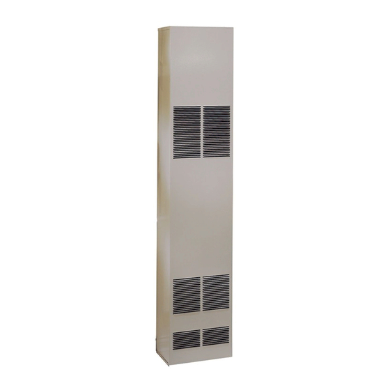
FAN TYPE
DIRECT VENT
WALL FURNACE
MODEL
DV-55SPP
WARNING: If the information in these instruc-
tions are not followed exactly, a fire or explosion
may result causing property damage, personal
injury or loss of life.
— Do not store or use gasoline or other flamma-
ble vapors and liquids in the vicinity of this or
any other appliance.
— WHAT TO DO IF YOU SMELL GAS
•
Do not try to light any appliance.
•
Do not touch any electrical switch; do not
use any phone in your building.
•
Immediately call your gas supplier from a
neighbor's phone. Follow the gas suppli-
er's instructions.
•
If you cannot reach your gas supplier, call
the fire department.
— Installation and service must be performed by
a qualified installer, service agency or the gas
supplier.
Page 1
Advertisement
Table of Contents

Related Manuals for Empire Heating Systems DV-55SPP


Summary of Contents for Empire Heating Systems DV-55SPP
-
Page 1: Installation Instructions
OWNER'S MANUAL FAN TYPE DIRECT VENT WALL FURNACE MODEL DV-55SPP Installer: Leave this manual with the appli- ance. WARNING: If the information in these instruc- Consumer: Retain this manual for future refer- tions are not followed exactly, a fire or explosion ence. -
Page 2: Table Of Contents
TABLE OF CONTENTS SECTION PAGE Important Safety Information ........................3 Safety Information for Users of LP Gas ......................4 Requirements for Massachusetts ........................5 Introduction ..............................6 Specifications ...............................6 Gas Supply ............................... 7-8 Clearances ..............................8 Installation Instructions .......................... 9-11 Lighting Instructions ..........................12 Pilot Flame Characteristics ........................13 Main Burner Flame Characteristics ......................13 Wiring ................................14 Service and Maintenance Suggestions .......................15... -
Page 3: Important Safety Information
IMPORTANT SAFETY INFORMATION THIS IS A HEATING APPLIANCE DO NOT OPERATE THIS APPLIANCE WITHOUT FRONT PANEL INSTALLED. Due to high temperatures the appliance should be located is imperative that control compartments, burners and • out of traffic and away from furniture and draperies. circulating air passageways of the appliance be kept clean. -
Page 4: Safety Information For Users Of Lp Gas
SAFETY INFORMATION FOR USERS OF LP-GAS Propane (LP-Gas) is a flammable gas which can cause fires by point with the members of your household. Someday when and explosions. In its natural state, propane is odorless and there may not be a minute to lose, everyone's safety will depend colorless. -
Page 5: Requirements For Massachusetts
REQUIREMENTS FOR MASSACHUSETTS For all side wall horizontally vented gas fueled equipment 3. SIGNAGE. A metal or plastic identification plate shall be installed in every dwelling, building or structure used in permanently mounted to the exterior of the building at a whole or in part for residential purposes, including those minimum height of eight (8) feet above grade directly in owned or operated by the Commonwealth and where the... -
Page 6: Introduction
Installation in Residential Garages match be used. The match will light the pilot faster than the piezo Gas utilization equipment in residential garages shall be installed under this condition. SPECIFICATIONS Model DV-55SPP Input BTU/HR 55,000 Height 82 3/8" Width 16"... -
Page 7: Gas Supply
GAS SUPPLY A manual main gas cock should be located in the vicinity of Locating Gas Supply the unit. Where none exists, or where its size or location is not The gas line can enter the unit either through the floor or outside adequate, contact your local authorized installer for installation wall. -
Page 8: Clearances
Checking Manifold Pressure Both Propane and Natural gas valves have a built-in pressure regu- lator in the gas valve. Natural gas models will have a manifold pressure of approximately 4.0" w.c. at the valve outlet with the inlet pressure to the valve from a minimum of 6.0" w.c. for the purpose of input adjustment to a maximum of 7.0"... -
Page 9: Installation Instructions
INSTALLATION INSTRUCTIONS Locating Wall Opening The furnace is to be located on an outside wall. Locate wall studs so that wall opening will be located between wall studs. The furnace is 16 inches in width and normal 16 inches on center studs will not allow the furnace to be recessed into the wall unless a stud is repositioned. - Page 10 INSTALLATION INSTRUCTIONS (continued) Cutting Vent Tubes This is the most important part of the installation. With the furnace installed on wall the 6" diameter air inlet tube and the 4" diam- eter flue outlet tube are to be marked and cut using the following procedure.
-
Page 11: Installation Instructions
INSTALLATION INSTRUCTIONS (continued) Apply furnace cement to 4" diameter flue outlet collar on Warning: When vinyl siding vent kit, DV-822 or 2" x 4" combustion chamber and to 4" diameter collar on vent cap. framing is added to an existing installation (furnace is Attach 4"... -
Page 12: Lighting Instructions
LIGHTING INSTRUCTIONS FOR YOUR SAFETY READ BEFORE LIGHTING WARNING: If you do not follow these instructions exactly, a fire or explosion may result causing property damage, personal injury or loss of life. A. This appliance has a pilot which must be lighted by •... -
Page 13: Pilot Flame Characteristics
PILOT FLAME CHARACTERISTICS PROPER FLAME ADJUSTMENT The correct pilot flame (Figure 11) will be blue, extending past the thermocouple. The flame will surround the thermocouple just below the tip. Natural gas pilots require adjusting when the inlet gas pressure is above 5"... -
Page 14: Wiring
WIRING Wiring The appliance, when installed, must be electrically grounded in ac- cordance with local codes or, in the absence of local codes, with the National Electrical Code, ANSI/NFPA 70 or Canadian Electrical Code, CSA C22.1, if an external electrical source is utilized. This appliance is equipped with a three-prong [grounding] plug for your protection against shock hazard and should be plugged directly into a properly grounded three-prong receptacle. -
Page 15: Service And Maintenance Suggestions
SERVICE & MAINTENANCE SUGGESTIONS Replacing Fan and Oiling the Motor If Electrode Does Not Produce Spark: The fan motor should be cleaned and oiled once each heating season. 1. Check wire connections. 2. Check gap for pilot burner to the electrode tip. Should be To reach the motor, withdraw the metal shroud surrounding the fan between 1/8"... -
Page 16: How To Order Repair Parts
HOW TO ORDER REPAIR PARTS Parts can be ordered only through your service person or dealer. For best results, the service person or dealer should order parts through the distributor. Parts can be shipped directly to the service person/dealer. All parts listed in the Parts List have a Part Number. When ordering parts, first obtain the Model Number from the name plate on your equipment. -
Page 17: Parts View
PARTS VIEW 12431-10-1008 Page 17... -
Page 18: Service Notes
SERVICE NOTES Page 18 12431-10-1008... - Page 19 SERVICE NOTES 12431-10-1008 Page 19...
- Page 20 Empire Comfort Systems Inc. EMPIRE EMPIRE 918 Freeburg Ave. Belleville, IL 62220 If you have a general question about our products, please e-mail us at info@empirecomfort.com. If you have a service or repair question, please contact your dealer. Comfort Systems www.empirecomfort.com Page 20 12431-10-1008...
Need help?
Do you have a question about the DV-55SPP and is the answer not in the manual?
Questions and answers