Hilti POS 15 Operating Instructions Manual
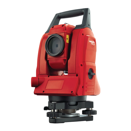
Total station
Hide thumbs
Also See for POS 15:
- Original operating instructions (16 pages) ,
- Quick start manual (126 pages)

Related Manuals for Hilti POS 15


Summary of Contents for Hilti POS 15
- Page 1 POS 15/18 Operating instructions Mode d’emploi Manual de instrucciones Manual de instruções Printed: 07.07.2013 | Doc-Nr: PUB / 5135739 / 000 / 00...
- Page 2 Printed: 07.07.2013 | Doc-Nr: PUB / 5135739 / 000 / 00...
- Page 3 Printed: 07.07.2013 | Doc-Nr: PUB / 5135739 / 000 / 00...
- Page 4 Printed: 07.07.2013 | Doc-Nr: PUB / 5135739 / 000 / 00...
- Page 5 Printed: 07.07.2013 | Doc-Nr: PUB / 5135739 / 000 / 00...
-
Page 6: Table Of Contents
Keep these pages open while studying the oper- Horizontal drive ating instructions. Tribrach footscrew In these operating instructions, the designation “the tool” £ Tribrach always refers to the POS 15 or POS 18. Laser plummet ¡ Guide light Rear casing section 1 Objective lens Carrying handle... -
Page 7: Laser Plummet
6.1.3 Technical terms ............. . 12 6.1.4 Telescope positions 4 3 . - Page 8 Electronic bubble level ............31 Correction of atmospheric influences .
-
Page 9: General Information
Hilti PROFIS Layout data output (export) ........ -
Page 10: Explanation Of The Pictograms And Other Information
2.2 Description of the tool The tool is designed for measuring distances and direc- The POS 15/18 total station can be used to determine the tions, calculating target positions in 3 dimensions and exact position of objects or points. The tool is equipped... -
Page 11: Items Supplied As Standard
3.8 V 5200 mAh Li-ion battery Reflector rod POW 10 adjusting key Laser warning plate Manufacturer’s certificate Operating instructions Hilti toolbox Optional: Hilti PROFIS Layout (PC software on CD‑ROM) Optional: Copy protection dongle for PC soft- ware Optional: USB data cable 3 Accessories Illustration... - Page 12 PUA 35 tripod POW 10 adjusting key For use by appropriately experienced persons only! Hilti PROFIS Layout PC application that allows positions (points) to be generated from CAD data and transferred to the tool. POA 91 copy protection dongle...
-
Page 13: Technical Data
45 mm (1.8") Compensator Type Dual-axis, liquid Working range ±3’ Accuracy 2" Angle measurement POS 15 accuracy (DIN 18723) 5" POS 18 accuracy (DIN 18723) 3" Angle reading system Diametral Distance measurement Range 340 m (1000 ft) Kodak 90% gray Accuracy ±3 mm + 2 ppm (0.01 ft + 2 ppm) -
Page 14: Safety Instructions
Do not render safety devices ineffective and do when used incorrectly by untrained personnel or when not remove information and warning notices. used not as directed. c) Have the tool repaired only at a Hilti Service Center. Failure to follow the correct procedures when... -
Page 15: Proper Organization Of The Work Area
Check the tool for damage before use. If the tool sons or toward yourself when setting up the tool. is found to be damaged, have it repaired at a Hilti b) Use the tool only within the defined application limits, service center. -
Page 16: Transport
View the tool at an angle when setting it up with 5.6 Transport the aid of the circular bubble level. The batteries must be insulated or removed from the k) Secure the battery compartment cover carefully tool before the tool is shipped or sent by mail. Leaking in order to ensure that the battery cannot fall batteries may damage the tool. -
Page 17: Technical Terms
6.1.3 Technical terms Tool axes Sighting axis Vertical axis Trunnion (tilt axis) Horizontal circle / horizontal angle The included angle of 70°- 40° = 30° can be calculated from the horizontal circle readings of 70° to one target and 30° to the other target. -
Page 18: Telescope Positions 4 3
Vertical circle / vertical angle As the vertical circle is aligned at 0° to the direction of gravity or at 0° to horizontal, angles are determined relative to the direction of gravity, so to speak. Using these values, the horizontal distance and vertical distance are calculated from the measured slope distance. 6.1.4 Telescope positions 4 3 The term “telescope position”... -
Page 19: Abbreviations And Their Meaning
Horizontal angle (HA) A horizontal angle is the difference between two readings from the ho- rizontal circle. However, a reading from one of the circles is also often described as an angle. Slope distance (SD) Distance from the center of the telescope to the point at which the laser beam strikes the target surface Horizontal distance (HD) The horizontal distance derived from the measured slope distance. -
Page 20: Angle Measurement System
Delta height Delta east Delta north dOffs Delta offset horz Delta line 6.2 Angle measurement system 6.2.1 Measuring principle The tool calculates the angle in each case from two circle readings. For the purpose of distance measurement, pulses transmitted along a visible laser beam at a certain wavelength are reflected from the object to which the measurement is being taken. -
Page 21: Targets
Check at regular intervals to ensure that the visible laser distancer beam is correctly adjusted and in line with the sighting axis. Send the tool to your nearest Hilti Service Center if adjustment is found necessary or if you are unsure. -
Page 22: Height Measurement
Reflector rod lengths POA 50 (metric) 100 mm 400 mm 700 mm 1,000 mm 1,300 mm POA 51 (imper- 4" 16" 28" 40" 52" ial) 6.4 Height measurement 6.4.1 Height measurement The tool can be used to measure heights or differences in height. Height measurements are made using the trigonometrical height measurement principle and are calculated accordingly. -
Page 23: Guide Light
Outdoors, however, the beam is visible only under certain conditions so its use for this purpose is not really feasible. 6.7 Data points The data from measurements taken with the Hilti total stations is used to generate measured points. Similarly, these measured points and their position descriptions are used in applications such as “Layout” or to define station locations. - Page 24 Enlarge the selected area. NOTE Point data assigned to a graphical element cannot be edited or deleted on the total station. This can only be done using Hilti PROFIS Layout. Selecting points from a list Cancel and return to previous screen.
-
Page 25: First Steps
7 First steps 7.1 Batteries The tool is equipped with two batteries which can supply power one after the other. The current state of battery charge (both batteries) is always shown. When changing batteries, one battery can remain in the tool and continue to provide power while the other battery is being charged. -
Page 26: Size Of The Touch Screen
7.5.2 Size of the touch screen The touch screen is approx. 74 x 56 mm (2.9 x 2.2 in) in size and has a resolution of 320 x 240 pixels. 7.5.3 Division of the touch screen The touch screen is divided into areas for operation of the tool and for displaying information to the user. Instructions and info for the user Battery and laser pointer status indicator Time and date indicator and entry line... -
Page 27: Touch Screen - Alphanumerical Keyboard
7.5.5 Touch screen – alphanumerical keyboard When alphanumerical data is required to be entered, the appropriate keyboard appears in the display automatically. The keyboard layout is as shown in the illustration below. Cancel and return to previous screen. Switch to lower case letters. Switch to numerical keys. -
Page 28: Switching On / Off
7.6 Switching on / off 7.6.1 Switching on Press and hold the on/off button for approx. 2 seconds. NOTE If the tool is starting from a fully switched-off state, the complete start-up procedure takes approx. 20 – 30 seconds, during which two different screens are displayed consecutively. The end of the start-up procedure has been reached when the tool shows that it requires to be leveled (see section 7.7.2). -
Page 29: Setting Up Over A Pipe Using The Laser Plummet
Increase laser plummet intensity (settings 1–4). Reduce laser plummet intensity (settings 1–4). Confirms leveling. Laser plummet indicator symbol. The heavier the line, the more intense the laser plummet lights. Electronic “bubble level” indic- ator. Center the bubbles. Once the electronic “bubble levels” have been centered, check that the laser plummet is aligned exactly with the mark on the ground and shift the position of the tool laterally on the tripod plate if necessary. -
Page 30: Setting The Horizontal Circle Display
Select the “Theodolite” applica- tion for setting horizontal circle readings. 7.8.1 Setting the horizontal circle display The horizontal circle reading is held, the tool aimed at the new target and the circle reading then released. Pause current horizontal circle reading. Cancel and return to the previ- ous screen without changing the horizontal value. -
Page 31: Zeroing The Circle Reading
Enter the horizontal angle value manually. Confirm the information shown. 7.8.3 Zeroing the circle reading The option Hz “Zero” can be used to zero the horizontal circle reading quickly and easily. Set current horizontal angle to 0. Quit function. Cancel and return to the previ- ous screen without changing the horizontal value. -
Page 32: System Settings
Toggle vertical angle display between degrees and %. 8 System settings 8.1 Configuration When in the program menu, the configuration button is used to jump directly to the configuration button. Return to previous view. Select the configuration menu. Cancel and return to previous screen. - Page 33 Cancel and return to previous screen. Continue to the next screen where further settings can be made. Exit and save settings. Settings for automatic shut-down parameters, beep tone and language selection. Cancel and return to previous screen. Return to previous view. Exit and save settings.
-
Page 34: Time And Date
8.2 Time and date The tool is equipped with an electronic system clock that is capable of displaying the time and date in various formats, taking the different world time zones and switching between summer and winter time into account. Select the menu for entering the date and time. -
Page 35: Function Menu (Fnc)
Time zones GMT -12 hrs to GMT +13 hrs The time zones are identified by capital cities. Auto summer time 9 Function menu (FNC) The FNC button is used to select the function menu. This menu selection can be made at any time. Menu for entering various atmo- spheric data. -
Page 36: Laser Pointer 6
9.2 Laser pointer 6 Switch the laser pointer on/off. 9.3 Display illumination Switch display illumination on/off or vary its intensity. The brighter the display, the more power is consumed. 9.4 Electronic bubble level See section 7.7.1 on setting up over a mark on the floor or ground using the laser plummet 9.5 Correction of atmospheric influences The tool uses a visible laser beam for distance measurement. -
Page 37: Correction Of Atmospheric Influences
9.5.1 Correction of atmospheric influences Menu for entering various atmo- spheric data. Apply settings and exit from the FNC menu. Select the option “ppm”. Cancel and return to previous screen. Select the applicable units and enter the pressure and temperature. Settings for atmospheric influences and the units used Units (pressure) mmHg... -
Page 38: Selecting A Project
Return to previous view. Select or create a new project. Confirm that the project shown is the current project. 10.1.2 Selecting a project Return to previous view. Show project information. Select or create a new project. Confirm the selected project. From the list shown, select the project that is to be used as the current project. -
Page 39: Project Information
10.1.4 Project information The current status of the project is shown with the project information, e.g. date and time of creation, number of stations and total number of the points saved. Confirm information shown and return to project selection. 10.2 Setting a station and orientation Please pay particular attention to the information given in this section. -
Page 40: Setting A Station Over A Point With Control Lines
4 alternative ways of setting the station Cancel and return to previous screen. Confirm selection and continue to station identification. NOTE The “Set station” process always includes setting a position and an orientation. When one of the four applications is started, such as Horizontal Layout, Vertical Layout, As-Built or Measure and Record, a station and orientation always have to be set. - Page 41 Cancel and return to previous screen. Confirm selection and continue to station identification. Setting up the tool over a point on a building control line The tool is set up over a point marked on the building control line, from which the points or items to be measured are easily visible.
- Page 42 10.2.2.2 Entering the target point A designation that clearly identifies the orientation point must be entered when data is saved. Enter name for the orientation point. Return to previous view. Continue to “Orientation meas- urement”. Measure angle and distance. Continue, showing the (re)calculated station height.
-
Page 43: Setting A Station "Anywhere", With Building Control Lines
Return to previous view. Enter axis shift manually. Take measurement to point. The axis, distance and height values are shown. The values can be individually labeled. Rotate axis. Continue to the next step. Rotating the axis The axis bearing (direction) can be rotated about the starting point. If the value entered is positive, the axis is rotated clockwise. - Page 44 Cancel and return to previous screen. Confirm selection and continue to station identification. Setting up the tool “anywhere”, with building control lines An unobstructed and convenient location should be chosen for setting up the tool, where two reference points on the same building control line are clearly visible and where a good line of sight to the points to be measured can be ensured as far as possible.
- Page 45 10.2.3.1 Measuring to the first reference point on a control line Enter the name of the orientation point. Return to previous view. Measure angle and distance. Continue to “Measure to the second reference point”. 10.2.3.2 Measuring to the second reference point Return to “Measuring to the first reference point”.
-
Page 46: Setting A Station Over A Point With Coordinates
Continue with rotating the axis and shifting the axis as described in the applicable sections. 10.2.4 Setting a station over a point with coordinates On many construction sites, measured points with coordinates already exist, or the positions of parts of the structure, building control lines or foundations etc. - Page 47 Enter station names. Return to previous view. Confirm entry of station data and continue with orientation. After the name for the station point has been entered, the corresponding coordinates or positions are searched for in the graphics data in memory. If no point data exists under the given name the coordinates have to be entered manually.
-
Page 48: Setting A Station "Anywhere", With Coordinates
Return to previous view. Continue to the next screen where further settings can be made. The dHD value shown is the difference between the measured distance and the distance calculated from the coordinates. Further points can be checked by pressing the “Next” button. In addition to the dHD, the dHA value (which is the difference between the measured horizontal angle and the horizontal angle calculated from the coordinates) is also shown in the display. - Page 49 Cancel and return to previous screen. Confirm and apply the entry. Setting up the tool “anywhere”, with coordinates An unobstructed and convenient location should be chosen for setting up the tool, where two coordinate points are clearly visible and where a good line of sight to the points to be measured can be ensured as far as possible. It is recommended that a mark is always first made on the ground or floor and the tool then set up over this mark.
- Page 50 10.2.5.1 Measuring to the first reference point Enter the name of the orientation point. Return to previous view. Measure angle and distance. Continue to “Measure to the second reference point”. Corresponding coordinates or positions are searched for in the graphic data saved in the system. If no point data exists under this name the coordinates have to be entered manually.
-
Page 51: Setting The Height
10.3 Setting the height If heights are also to be used in addition to setting the station and orientation, i.e. target heights are to be determined or laid out, the height of the center of the telescope must also be defined. Two different methods can be used to set the height: If the height of the point on the floor or ground is known, the height of the tool is then measured. - Page 52 Cancel and return to previous screen. Measure angle and distance. Continue, showing the (re)calculated station height. Showing the recalculated station height after measurement The recalculated station height is shown after taking the angle and distance measurements and it can then be confirmed or canceled.
-
Page 53: Setting A Station With Coordinates (Height Option "On")
After the station has been set, the user can continue with the actual main application previously selected. 10.3.2 Setting a station with coordinates (height option “on”) Defining a new station height The station height can be determined in three different ways: Direct manual entry of the station height The station height is determined by manually entering the height of a height mark and by measuring the vertical angle and distance. - Page 54 Cancel and return to previous screen. Measure angle and distance. Continue, showing the (re)calculated station height. Showing the recalculated station height after measurement The recalculated station height is shown after taking the angle and distance measurements and it can then be confirmed or canceled.
-
Page 55: Applications
Showing the recalculated station height after measurement The recalculated station height is shown after taking the angle and distance measurements and it can then be confirmed or canceled. Cancel and return to previous screen. Setting the station. Set station If the “With heights” option has been selected, the station heights will be shown in the “Set station” screen. These can be confirmed or redefined. -
Page 56: Laying Out With Building Control Lines
The “Horizontal Layout” application is started by way of the corresponding button in the in the application menu. Return to previous view. Continue to “Select further ap- plications”. Select the “Horizontal layout” application. After starting the application, the projects or list of projects (see section 13.2) is shown for selection as well as the corresponding station selection or station setup. - Page 57 Return to previous view. Confirm entry and continue, showing display for aligning the tool with the point to be staked or marked out. NOTE Layout values on the building control line in a forwards or backwards direction from the tool station are line (longitudinal) values and those to the right or left of the building control line are offset values.
- Page 58 P0 is the position of the tool after setting up. P1 is the point to be laid out and the tool is already aimed at this point. The reflector bearer is standing close to the point (distance) calculated. After each distance measurement the tool indicates the amount by which the reflector bearer must move, forwards or backwards, towards the point to be laid out.
-
Page 59: Laying Out With Coordinates
The tip of the reflector must be moved upwards by the amount indicated. Down The tip of the reflector must be moved downwards by the amount indicated. Layout results Screen showing the layout differences in terms of line, offset and height based on the last target point measurement. Return to entry of layout values. - Page 60 Return to previous view. Confirm entry and continue, showing display for aligning the tool with the point to be staked or marked out. Entering the layout points (from a CAD drawing) The layout points are selected directly from a CAD drawing. With this method, the point is already incorporated in the drawing as a three-dimensional or two-dimensional point and can be extracted accordingly.
- Page 61 After each distance measurement the tool indicates the amount by which the reflector bearer must move towards the point to be laid out. Layout results with coordinates Shows the layout difference in terms of coordinates based on the last distance and angle measurements. Return to entry of layout values.
-
Page 62: Vertical Layout (Vert. Layout)
Difference in height. dH = height (measured) – height (entered) Difference in coordinate easting based on the coordin- ate reference system. dE = delta east (measured) – delta east (entered) NOTE The procedure for a horizontal layout with coordinates is the same as for a layout based on a building control line, with the exception that coordinates or coordinate differences are entered or shown as results instead of line or offset distances. -
Page 63: Vertical Layout With Building Control Lines
Return to previous view. Continue to “Select further ap- plications”. Select the “Vertical layout” ap- plication. After starting the application, the projects or list of projects is shown for selection as well as the corresponding station selection or station setup. The “Vertical layout”... - Page 64 NOTE The procedure for setting up the station is the same as for setting up the station “anywhere” with building control lines, with the difference that the first reference point is set at the zero point of the building control line system in the vertical plane and the second reference point defines the direction of the vertical plane relative to the tool system.
- Page 65 Where possible, the person holding the rod can move into position on the sighting line with the aid of the guide light. Return to entry of layout values. Measure distance and continue, showing layout corrections. Layout corrections Using the corrections displayed, the target bearer or target is guided Up, Down, Left, Right into position. With the aid of distance measurement, a correction Forward or Back can also be made.
-
Page 66: Vertical Layout With Coordinates
Return to entry of layout values. Save the layout values and last differences. Enter the next point. Saving data for staking out with building control lines Pt ID Name of layout point. Line (entered) Line distance entered, relative to the reference axis. Height (entered) Height entered. - Page 67 Entering the layout values (from a CAD drawing) With this method the layout points are selected directly from CAD graphics. With this method, the point is already incorporated in the drawing as a three-dimensional or two-dimensional point and can be extracted accordingly. Shows the point selected from the graphical display.
-
Page 68: As-Built
Difference in height. dH = height (measured) – height (entered) Difference in coordinate easting based on the coordin- ate reference system. dE = delta east (measured) – delta east (entered) NOTE The vertical layout always uses three-dimensional point descriptions. In layouts with control lines and layouts with coordinates, the line, height and offset dimensions are used. -
Page 69: As-Built With Building Control Lines
After starting the application, the projects or list of projects is shown for selection as well as the corresponding station selection or station setup. The “As-built” application begins after station setup is completed. Depending on the station selected, there are two alternative methods for determining the as-built measurement point: Measuring as-built points using building control lines Measuring as-built points with coordinates and/or points based on CAD drawings. - Page 70 Return to entry of layout values. Measure distance and continue, showing deviations. Results of as-built measurements Shows the difference in position in terms of Line, Offset and Height based on the last distance and angle measurements. Return to entry of layout values. Save the layout values and last differences.
-
Page 71: As-Built With Coordinates
11.3.3 As-built with coordinates Entering an as-built point An as-built point with point coordinates can be entered in three different ways: Manual entry of point coordinates. Selection of point coordinates from a list of points saved in memory. Selection of point coordinates from a CAD drawing with points saved in memory. Return to previous view. -
Page 72: Missing Line
Return to entry of layout values. Save the layout values and last differences. Enter the next point. Saving data for staking out with coordinates Pt ID Name of layout point. Northings (entered) The northings entered refer to the coordinate reference system. - Page 73 Using “Missing line” to determine inclination Return to previous view. Continue to “Select further ap- plications”. Select the “Missing line” applica- tion. After selecting the application the list of projects is displayed. The station does not have to be set for this application. Two different methods can be used to determine the missing line: Using the results of measurements to the first and all other measured points.
- Page 74 2nd method – relationship between the first and second point Example with points on the ground / floor Measure the first two points. After obtaining the result, choose a new line and measure the new first point and the new second point. Measuring to the first reference point Return to project selection.
-
Page 75: Measure And Record
The results shown Return to previous view. Save results. Alternative for new line. Continue to entry of a new 1st. reference point. Alternative for next point: Calcu- late missing line relative to 1st reference point 11.5 Measure and record 11.5.1 The principle of “Measure and record” “Measure and record”... - Page 76 P0 is the position of the tool after setting up. If angles and distances to target points are measured, the corresponding building control line distances L and Q are calculated and saved in memory. Measuring points with building control lines Measuring can begin as soon as station setup has been completed.
-
Page 77: Measure And Record With Coordinates
11.5.3 Measure and record with coordinates The positions of the measured points relate to the same coordinate system used for the station setup and are described or, respectively, indicated by coordinate values E or Y, N or X and H for the heights. P0 is the position of the tool after setting up. -
Page 78: Vertical Alignment
NOTE The horizontal distance value is fixed by measuring the distance. If the telescope is subsequently moved, only the horizontal angle and vertical angle values change. It is sometimes difficult, or even impossible, to make an exact measurement to a certain point (e.g. to the middle of a post or tree). -
Page 79: Area Measurement
After selecting the application the list of projects is displayed. The station does not have to be set for this application. Measurements to the 1st reference point The angle and distance are measured to the 1st reference point. The distance can be measured directly to the point or using the reflector rod, depending on ease of access to the 1st reference point. - Page 80 NOTE The points must be measured in such a way that the lines between the measured points do not cross each other, otherwise an incorrect area measurement will result. Return to previous view. Continue to “Select further ap- plications”. Select the “Area measurement” application.
-
Page 81: Indirect Height Measurement
Show the result of area meas- urement. Results The results are saved in internal memory and can be displayed on a PC or printed out using Hilti PROFIS Layout. Return to project selection. Save the results of area meas- urement. -
Page 82: Indirect Height Measurement
Return to previous view. Continue to “Select further ap- plications”. Select the “Indirect height meas- urement” application. After selecting the application the list of projects is displayed. The station does not have to be set for this application. 11.8.2 Indirect height measurement Measurements to the 1st reference point The angle and distance to the 1st reference point are measured. -
Page 83: Determining A Point In Relation To An Axis
11.9 Determining a point in relation to an axis 11.9.1 The principle of “Point in relation to axis” The application “Point in relation to axis”, can be used to determine the position of a point (e.g. a reference point) in relation to the axis. -
Page 84: Checking Points In Relation To The Axis
Return to previous view. Enter axis shift manually. Take measurement to point. The axis, distance and height values are shown. The values can be individually labeled. Rotate axis. Continue to the next step. Rotating the axis The axis bearing (direction) can be rotated about the starting point. If the value entered is positive, the axis is rotated clockwise. -
Page 85: Data And Data Handling
12.2.3 Points with graphical elements With the aid of Hilti PROFIS Layout, graphical data can be transferred from a CAD environment, shown on the screen and selected for use. The Hilti system allows points and graphical elements to be created in various ways using Hilti PROFIS Layout, and to subsequently transfer these to the total station for further use. -
Page 86: With Hilti Profis Layout
The point data generated in this way is placed visibly on the original graphics elements from CAD. The data in a CAD format can exist in various “layers”. When this data is transferred to Hilti PROFIS Layout it is merged into a single layer. -
Page 87: Selecting A Job
Creating, deleting and copying new projects. Entering, editing and deleting the coordinates of control points (fixed points). Displaying and deleting measured points. Return to previous view. Select the “Data manager” ap- plication. NOTE Control points (fixed points) can be edited only when these are not attached to graphical data. 13.2 Selecting a job After starting the Data Manager, the list of existing jobs in internal memory is shown. -
Page 88: Fixed Points (Control Points Or Layout Points)
13.2.1 Fixed points (control points or layout points) After selecting the applicable job, the option “Points” can be selected in order to enter points with coordinates or to edit or delete existing points with coordinates. 13.2.1.1 Entering points with coordinates Manual entry of the point name and coordinates. -
Page 89: Measured Points
NOTE Points with attached graphics can neither be changed nor deleted. This is possible only when working on a PC with Hilti PROFIS Layout. 13.2.2 Measured points After selecting the applicable project, the stations and their associated measured points can be displayed. - Page 90 Cancel and return to previous screen. Select a point from a plan. Delete the station and all associ- ated measured points. Select a point from a list. Confirm and apply the entry. 13.2.2.2 Selecting measured points After selecting the station, a measured point can be searched for by making a manual entry, selected from a list of measured points or selected from the graphical display.
-
Page 91: Deleting A Project
Cancel and return to previous screen. Select a point from a plan. Delete point. Select a point from a list. Confirm and apply the entry. 13.2.2.3 Deleting and displaying measured points After selecting the measured point, the measured values and coordinates can be displayed and the measured point then deleted. -
Page 92: Creating A New Project
13.4 Creating a new project When entering the name of a new project, care must be taken to ensure that the name of the project does not already exist in memory. Enter project name. Cancel and return to project se- lection. -
Page 93: Exchanging Data With A Pc
Data can be exchanged using either the USB data cable supplied or a USB memory device (e.g. flash drive). 14.2 HILTI PROFIS Layout Data is always exchanged as a complete project, i.e. all data belonging to a project is exchanged between the Hilti total station and Hilti PROFIS Layout. -
Page 94: Hilti Profis Layout Data Output (Export)
No provision has been made for direct data exchange between the total station and other PC systems, this can be done only by using Hilti PROFIS Layout. 14.2.2 Hilti PROFIS Layout data output (export) Data is saved in the following applications and can be exported with the aid of Hilti PROFIS Layout in various formats: Horizontal layout Vertical layout... -
Page 95: In-The-Field Calibration
NOTE In the event of uncertainty the tool should be returned to Hilti Service for checking. Set up the tool in a steady, secure position on a good tripod. - Page 96 Select a clearly visible target within ± 3 degrees from horizontal at a distance of approx. 70-120 m and sight this target carefully. NOTE Find a suitable target that can be sighted easily and accurately. NOTE If the tool is not in the 1st telescope position a message in the display will instruct you to bring it into this position.
-
Page 97: Hilti Calibration Service
When the new calibration values are adopted, the new settings for the compensator are also adopted. 15.3 Hilti Calibration Service We recommend that the tool is checked by the Hilti Calibration Service at regular intervals in order to verify its reliability in accordance with standards and legal requirements. -
Page 98: Care And Maintenance
Most of the materials from which Hilti tools or appliances are manufactured can be recycled. The materials must be correctly separated before they can be recycled. In many countries, Hilti has already made arrangements for taking back old tools or appliances for recycling. -
Page 99: Manufacturer's Warranty
18 Manufacturer’s warranty Hilti warrants that the tool supplied is free of defects in Additional claims are excluded, unless stringent na- material and workmanship. This warranty is valid so long tional rules prohibit such exclusion. In particular, Hilti as the tool is operated and handled correctly, cleaned... -
Page 100: Ec Declaration Of Conformity (Original)
86916 Kaufering Deutschland We declare, on our sole responsibility, that this product complies with the following directives and standards: 2011/65/EU, 2006/95/EC, 2004/108/EC. Hilti Corporation, Feldkircherstrasse 100, FL‑9494 Schaan Paolo Luccini Matthias Gillner Head of BA Quality and Process Man- Executive Vice President agement Business Area Electric Tools &... - Page 101 Point in relation to axis ....3, 78 Hilti Calibration Service ....4, 92 Position of the station .
- Page 102 Total station ..... . 6 Tribrach ......1 Switching off .
- Page 103 Tel.: +423 / 234 21 11 Fax:+423 / 234 29 65 www.hilti.com Hilti = registered trademark of Hilti Corp., Schaan W 3881 | 0113 | 00-Pos. 6 | 1 Printed in Germany © 2013 Right of technical and programme changes reserved S. E. & O 433674 / A3 Printed: 07.07.2013 | Doc-Nr: PUB / 5135739 / 000 / 00...
Need help?
Do you have a question about the POS 15 and is the answer not in the manual?
Questions and answers