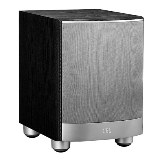
JBL SUB10 Service Manual
Amplifier/subwoofer venue series
Hide thumbs
Also See for SUB10:
- Service manual (27 pages) ,
- Owner's manual (9 pages) ,
- Owner's manual (9 pages)
Advertisement
Table of Contents
- 1 Table of Contents
- 2 Basic Specifications
- 3 Packaging
- 4 Detailed Specifications
- 5 System Connections
- 6 Operation
- 7 Test Set-Up and Procedure
- 8 Exploded View/Parts List
- 9 Block Diagram
- 10 120V Electrical Parts List
- 11 Pcb Drawings
- 12 Integrated Circuit/Transistor Pinouts
- 13 120V Schematics
- Download this manual
Advertisement
Table of Contents

Related Manuals for JBL SUB10


Summary of Contents for JBL SUB10
- Page 1 ™ Venue Series SUB10 Amplifier/Subwoofer SERVICE MANUAL JBL Consumer Products 250 Crossways Park Dr. Woodbury, New York 11797 Rev2 8/2006...
-
Page 2: Table Of Contents
EXPLODED VIEW/PARTS LIST…………………………………..9 BLOCK DIAGRAM..……………………………………….…..10 120V ELECTRICAL PARTS LIST ……………………………….11 PCB DRAWINGS………………..………………………………...15 INTEGRATED CIRCUIT/TRANSISTOR PINOUTS…………..21 120V SCHEMATICS.……….…………….…………..…. ………22 BASIC SPECIFICATIONS SUB10 Subwoofer 27Hz – 150Hz Frequency response: 150W Continuous RMS power Amplifier Power output: 250W † Amplifier Peak Dynamic Power 50Hz –... -
Page 3: Packaging
SUB10 Venture Series... -
Page 4: Detailed Specifications
SUB10 Venture Series JBL Venue Sub10 150W Powered Sub/ Plate Amp LINE VOLTAGE Yes/No Hi/Lo Line Unit Notes US 120vac/60Hz 108-132 Vrms Normal Operation EU 230vac/50-60Hz 207-264 Vrms Normal operation, MOMS required Asia 100vac/50Hz 90-110 Vrms Normal Operation Parameter Specification... - Page 5 SUB10 Venture Series Parameter Specification Unit QA Test Limits Conditions Notes sec. functional AC Power Applied Power on Delay time Transients/Pops ATO Transient mV-peak @ Speaker Outputs @ Speaker Outputs AC Line cycled from OFF to ON Turn-on Transient mV-peak...
-
Page 6: System Connections
SUB10 Venture Series SYSTEM CONNECTIONS If you have a Dolby ® Digital or DTS ® receiver/processor with a low-frequency- If your receiver/processor does not have subwoofer outputs for the left and effects (LFE) or subwoofer output: right channels or an LFE output, connect speaker wire from your receiver/... - Page 7 SUB10 Venture Series SPEAKER LEVEL LINE LEVEL IN GREEN: ON RED: STAND-BY PHASE AUTO ON T3.15A L/250V "WAR NING : FOR CONTINUED PROTECTION AGAINST RISK OF FIRE, REPLACE ONLY WITH SAME TYPE T 3.15A L/250V FUSE" "AVE R TIS S E ME NT: UTILISEZ UN FUSIBLE DE RECHANGE DE MEME ™...
-
Page 8: Operation
SUB10 Venture Series OPERATION Power On The enclosure may be cleaned using a soft cloth to remove fingerprints or to Plug your subwoofer’s AC cord into a wall outlet. Do not use the outlets on the wipe off dust. back of the receiver. -
Page 9: Test Set-Up And Procedure
SUB10 Venture Series SUB10 Test Set Up and Procedure Equipment needed: • Function/signal generator/sweep generator • Integrated Amplifier • Multimeter • Speaker cables General Unit Function (UUT = Unit Under Test) 1) From the signal generator, connect line level (RCA) cables to the Subwoofer Line Level Input jacks L/R on the UUT. -
Page 10: Exploded View/Parts List
SUB10 Venture Series... -
Page 11: Block Diagram
SUB10 Venture Series... -
Page 12: 120V Electrical Parts List
SUB10 Venture Series SUB10 120V Electrical parts list Part number Description Qty Reference Designator PREAMP PCB Resistors R201,R202 110-12472j52-e Resistor4.7K 1/2W ±5% CF 52mm (RoHS) R213,R214,R215,R254 110-16102j26-e Resistor 1K 1/6W ±5% CF 26mm (RoHS) R209,R212,R216,R217,R220,R221,R222,R228, Resistor10K 1/6W ±5% CF 26mm... - Page 13 SUB10 Venture Series Part number Description Qty Reference Designator PREAMP PCB D209, 195-10204hgw-e double color LED 204HGW 3 ¢(RoHS) Miscellaneous for D209, 162-50062001-e 2PIN 60mm red/black JK201, 174-0rca326p-e JACK RCA-326 (RoHS) JK203, 174-2wp810a-e SPK JACK 8P red up black down with cap 175-1c07v01-e wire connector &base7PIN PITCH=2.5mm (RoHS)
- Page 14 SUB10 Venture Series Part number Description Qty Reference Designator MAIN PCB 135-3226m50-e electrolytic cap 22U 50V ±20% C505,C506, C118, 135-3227m16-e electrolytic cap 220U 16V ±20% 135-3476m16-e electrolytic cap47U 16V ±20% C318, Semiconductors U301 190-16tl074cn-e *I.C TL074CN ST (RoHS) DUAL OP-AMP...
- Page 15 M3 solder t=0.3 (RoHS) 317-000-00037-0LAE heat sink 83.5*50.5*27.5H 323-AL-00056-0LAE EVAgasket 150*15*1t UL(RoHS) 333-EVA-00219-0BAE M3*8 machine screw (RoHS) 351-AM03008A078-E 162-a040d005-e spkr wire red and black#1015 add #205 250 pin(RoHS) 302-AL-00020-1LCE rear board 270*215*2.5T SUB10 AL (RoHS) wire clip SB4F-2 black(RoHS) 335-NYL-05015-0BAE...
-
Page 16: Pcb Drawings
SUB10 Venture Series... - Page 17 SUB10 Venture Series...
- Page 18 SUB10 Venture Series...
- Page 19 SUB10 Venture Series...
- Page 20 SUB10 Venture Series...
- Page 21 SUB10 Venture Series...
-
Page 22: Integrated Circuit/Transistor Pinouts
SUB10 Venture Series , IC1... -
Page 23: 120V Schematics
SUB10 Venture Series... - Page 24 SUB10 Venture Series...
- Page 25 SUB10 Venture Series...
- Page 26 SUB10 Venture Series...
Need help?
Do you have a question about the SUB10 and is the answer not in the manual?
Questions and answers