Table of Contents
Advertisement
Quick Links
Advertisement
Table of Contents

Subscribe to Our Youtube Channel
Related Manuals for Interlogix IFS MCR300-1T-2S


Summary of Contents for Interlogix IFS MCR300-1T-2S
- Page 1 IFS MCR300-1T-2S User Manual P/N 1072686 • REV A • ISS 23OCT13...
- Page 2 © 2013 United Technologies Corporation Copyright Interlogix is part of UTC Climate Controls & Security, a unit of United Technologies Corporation. All rights reserved. The IFS MCR300-1T-2S name and logo are trademarks of United Trademarks and Technologies. patents Other trade names used in this document may be trademarks or registered trademarks of the manufacturers or vendors of the respective products.
-
Page 3: Table Of Contents
TABLE OF CONTENTS 1 . INTRODUCTION..................4 1 .1 C .........................4 HECKLIST 1 .2 P ......................4 RODUCT ESCRIPTION 1 .3 P ......................5 RODUCT EATURES 1 .4 P ....................6 RODUCT PECIFICATION 2 . HARDWARE DESCRIPTION ..............7 2 .1 P ......................7 RODUCT UTLOOK 2 .2 F... -
Page 4: Introduction
1. Introduction 1.1 Checklist Check the contents of your package for following parts: MCR300-1T-2S User's Manual x 1 5V / 2.5A AC-DC Power Adapter x 1 If any of these pieces are missing or damaged, please contact your dealer immediately, if possible, retain the carton including the original packing material, and use them against to repack the product in case there is a need to return it to us for repair. -
Page 5: Product Features
1.3 Product Features Standard ■ • Comply with IEEE 802.3 10Base-T • Comply with IEEE 802.3u 100Base-TX • Comply with IEEE 802.3ab 1000Base-T • Comply with IEEE 802.3z 1000Base-SX / LX • IEEE 802.3x Full-Duplex Flow-Control, Back-Pressure in Half-Duplex eliminate packets loss Interface ■... -
Page 6: Product Specification
1.4 Product Specification MCR300-1T-2S Model Hardware Specification Hardware Version 1 x 10/100/1000Base-T port Copper Ports 2 x 1000Base-X SFP slots Fiber Twisted-Pair 10Base-T: 2-Pair UTP CAT. 3,4,5, up to 100 meters Cable 100Base-TX: 2-Pair UTP CAT. 5, 5e up to 100 meters 1000Base-T: 4-Pair UTP CAT. -
Page 7: Hardware Description
2. Hardware Description This product provides three different running speeds – 10Mbps, 100Mbps and 1000Mbps in the same Gigabit Media Converter and automatically distinguishes the speed of incoming connection. This section describes the functionalities of MCR300-1T-2S components and guides how to install it on the desktop or shelf. Basic knowledge of networking is assumed. -
Page 8: Front Panel
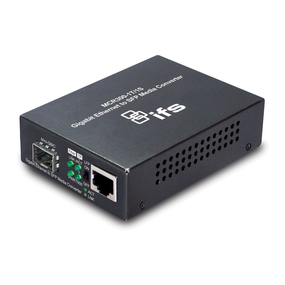
2.2 Front Panel The Front Panel of the Gigabit Media Converter consists of two 1000Base-X SFP slots and one Auto-Sensing 10/100/1000Mbps Ethernet RJ-45 Port. Figure 2 shows a front panel of Gigabit Media Converter. Figure 2-2-1: MCR300-1T-2S Front Panel 2.2.1 LED Indicators System Color Function... -
Page 9: Rear Panel
2.3 Rear Panel The rear panel of the Gigabit Media Converter indicates one DC jack, which accepts input power with 5V DC 2A. Figure 2-3-1: One DC jack for DC power input Power Notice: Power Information: the power jack of MCR300-1T-2S is with 2.5mm in the central post and required +5VDC power input. It will conform to the bundled AC-DC adapter and IFS’s Media Chassis. -
Page 10: Redundancy Overview
Redundancy Overview The MCR300-1T-2S provides rapid fiber redundancy of link for highly critical Ethernet applications. The redundant-mode supports auto-recover function. If the destination port of a packet is link down, it forwards the packet to the other port of the backup pair. The following figure shows the redundant function. -
Page 11: Install The Media Converter
2.5 Install the Media Converter This section describes how to install your Gigabit Media Converter and make connections to the Gigabit Media Converter. Please read the following topics and perform the procedures in the order being presented. The hardware installation of Gigabit Media Converter do not need software configuration. -
Page 12: Media Chassis Installation
Approved IFS SFP Transceivers The MCR300-1T-2S Gigabit Media Converter supports both Single mode and Multi-mode SFP transceiver. The following list of approved IFS SFP transceivers is correct at the time of publication: SFP Description UTC Model S30-1SLC/A-10 SFP, LC Connector, Single Mode, Gigabit, 1 fiber, 1310nm/1550nm, 10km , A End S30-1SLC/A-20 SFP, LC Connector, Single Mode, Gigabit, 1 fiber, 1310nm/1550nm, 20km, A End S30-1SLC/A-60... -
Page 13: Optional Din-Rail Installation
1. Never push the converter into the slot with violent, it could damage the chassis. 2. The Media Converter Chassis supports hot-swap; there is no need to turn off the whole chassis before slide in the new converter. 2.5.3 Optional DIN-Rail Installation There are two DIN-Rail holes on the left side of the MCR300-1T-2Sthat allows it can be easily installed with DIN-Rail mounting. - Page 14 Step 3: Check the DIN-Rail is tightly on the track. You must use the screws supplied with the mounting brackets. Damage caused to the parts by using incorrect screws would invalidate your warranty. - 14 -...
-
Page 15: Appendix A Networking Connection
Appendix A Networking Connection A.1 Data RJ-45 Pin Assignments - 1000Mbps, 1000Base-T PIN NO MDI-X BI_DA+ BI_DB+ BI_DA- BI_DB- BI_DB+ BI_DA+ BI_DC+ BI_DD+ BI_DC- BI_DD- BI_DB- BI_DA- BI_DD+ BI_DC+ BI_DD- BI_DC- Implicit implementation of the crossover function within a twisted-pair cable, or at a wiring panel, while not expressly forbidden, is beyond the scope of this standard. - Page 16 There are 8 wires on a standard UTP/STP cable and each wire is color-coded. The following shows the pin allocation and color of straight cable and crossover cable connection: Straight Cable SIDE 1 SIDE2 1 = White / 1 = White / SIDE 1 Orange Orange...
-
Page 17: Fiber-Optic Cable Connection Parameter
A.3 Fiber-Optic Cable Connection Parameter The wiring details are as below: Cables: Standard Fiber Type Cable Specification 1000Base‐SX(850nm) Multi‐mode 50/125μm or 62.5/125μm 1000Base‐LX(1300nm) Multi‐mode 50/125μm or 62.5/125μm Single‐mode 9/125μm Wiring Distances: Standard Fiber Diameter (micron) Modal Bandwidth (MHz * Max. Distance (meters) km) 1000Base‐SX MM 62.5 100 220 62.5 200 275 50 400 500 50 500 550 1000Base‐LX MM ...
Need help?
Do you have a question about the IFS MCR300-1T-2S and is the answer not in the manual?
Questions and answers