
Subscribe to Our Youtube Channel
Related Manuals for Interlogix DE7100-EE


Summary of Contents for Interlogix DE7100-EE
- Page 1 DE7100-EE DE7200-M DE7100-ME DE7200-S DE7100-SE DE7200-MM DE7100-MM DE7200-SS DE7100-MS DE7200-MS DE7100-SS IFS EtherNav Installation & Operation Instructions P/N 1062843 • REV B • ISS 01AUG11...
- Page 2 DE7100 SERIES 10 / 100 Transmit + (Pin 1) Transmit - (Pin 2) MIDI Switch Off Receive + (Pin 3) (All Electrical Ports) Receive - (Pin 6) NOTE: Pins 4, 5, 7, 8 are not used. 10 / 100 Receive + (Pin 1) MIDI Switch On Receive - (Pin 2) Transmit + (Pin 3)
- Page 3 DE7100 SERIES Fiber port A Fiber port B Link Speed (Channels A&B) GRN = 100 RED or OFF = 10 D Simplex/Duplex (Channels A&B) GRN or YEL = DUPLEX OFF = SIMPLEX Power connection F Power LED illuminates with fiber connection LOS A&B switch MDI On/Off Fiber link contacts connection I Port connection...
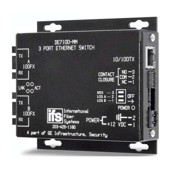
- Page 4 DE7200-M OPTICAL ETHERNET MEDIA CONVERTER 10/100TX 10/100TX NO - 3 CONTACT COM - 2 CLOSURE NC - 1 MDI - 3 Inter n ati onal NC - 2 F ib er LOS B - 1 100FX Sy s tem s POWER Inc or po ra ted POWER...
- Page 5 IF YOUR POWER OUTLET DOES NOT HAVE A CONNECTION TO GROUND: For proper installation the DE7100-XX stand alone units must be attached to earth ground. Ordinarily, this is accomplished through the power supply. If your power outlet does not have a ground prong then a wire must be attached from the power connector to ground.
- Page 6 FCC Compliance This device complies with Part 15 of the FCC Rules. Operation is subject to the following two conditions: (1) This device may not cause harmful interference, and (2) this device must accept any interference received, including interference that may cause undesirable operation. Changes or modifications not expressly approved by International Fiber Systems, Inc.
- Page 7 Note: Be ready at the equipment before calling. Online Another great resource for assistance with your Interlogix product is our online publication library. To access the library, go to our website at the following location: http://www.interlogix.com/transmission Many Interlogix documents are provided as PDFs (portable document format). To read these documents, you will...
-
Page 8: Required Tools
Product Disassembly Instructions for WEEE Per European Directive 2002/95/EC Waste Electrical and Electronic Equipment Required Tools: One number 2 Phillips (crosstip) screwdriver. One number 2 flat screwdriver. For the enclosed box version: 1. Locate and remove box cover securement screws. Usually, but not limited to, at least 4 screws. - Page 9 Copyright © 2011 UTC Fire & Security. All rights reserved. Trademarks and Interlogix and IFS names and logos are trademarks of patents UTC Fire & Security. Other trade names used in this document may be trademarks or registered trademarks of the manufacturers or vendors of the respective products.
Need help?
Do you have a question about the DE7100-EE and is the answer not in the manual?
Questions and answers