Table of Contents
Advertisement
ELECTRIC WATER HEATER
INSTALLATION & OPERATING
INSTRUCTION MANUAL
THE MANUFACTURER OF THIS HEATER WILL NOT BE LIABLE FOR
ANY DAMAGE RESULTING FROM FAILURE TO COMPLY WITH THESE
INSTRUCTIONS. READ THESE INSTRUCTIONS THOROUGHLY
BEFORE STARTING.
For safety, convenience, and best performance, we recommend
this water heater be installed and serviced by a plumbing
professional.
238-43565-00H REV 8/10
Advertisement
Chapters
Table of Contents

Related Manuals for Bradford White ELECTRIC WATER HEATER


Summary of Contents for Bradford White ELECTRIC WATER HEATER
- Page 1 ELECTRIC WATER HEATER INSTALLATION & OPERATING INSTRUCTION MANUAL THE MANUFACTURER OF THIS HEATER WILL NOT BE LIABLE FOR ANY DAMAGE RESULTING FROM FAILURE TO COMPLY WITH THESE INSTRUCTIONS. READ THESE INSTRUCTIONS THOROUGHLY BEFORE STARTING. For safety, convenience, and best performance, we recommend this water heater be installed and serviced by a plumbing professional.
-
Page 2: Table Of Contents
This installation, operation and instruction manual will explain in detail the installation and maintenance of your new Electric Water Heater. We strongly recommend that you contact a plumbing professional for the installation of this water heater. -
Page 3: General Information
GENERAL INFORMATION This water heater must be installed in accordance with local codes. In the absence of local codes, install this water heater in accordance with national or regional requirements. The best efficiency and longest product life is obtained only when the water heater is installed, adjusted and operated in accordance with these Installation and Operating Instructions. -
Page 4: Installation
General Information continued- A sacrificial anode(s) is used to extend tank life. Removal of any anode, for any reason, will shorten the products useful life. In areas where water is unusually active, an odor may occur at the hot water faucet due to a reaction between the sacrificial anode and impurities in the water. - Page 5 Locating The Water Heater continued- Water heater corrosion and component failure can be caused by the heating and breakdown of airborne chemical vapors. Examples of some typical compounds that are potentially corrosive are: spray can propellants, cleaning solvents, refrigerator and air conditioning refrigerants, swimming pool chemicals, calcium or sodium chloride, waxes and process chemicals.
-
Page 6: Water Connections
Water Connections NOTE: BEFORE PROCEEDING WITH THE INSTALLATION, CLOSE THE MAIN WATER SUPPLY VALVE. After shutting the main water supply valve, open a faucet to relieve the water line pressure to prevent any water from leaking out of the pipes while making the water connections to the water heater. - Page 7 Water Connections continued- WARNING For protection against excessive temperatures and pressure, install temperature and pressure protective equipment required by local codes, but not less than a combination temperature and pressure relief valve certified by a nationally recognized testing laboratory that maintains periodic inspection of production of listed equipment or materials, as meeting the Requirements for Relief Valves and Automatic Gas Shutoff Devices for Hot Water Supply Systems, ANSI Z21.22, and the Standard...
- Page 8 Water Connections continued- WARNING Hydrogen gas can be produced in a hot water system served by this water heater that has not been used for a long period of time (generally two weeks or more). Hydrogen gas is extremely flammable. To reduce the risk of injury under these conditions, it is recommended that the hot water faucet be opened for several minutes at the kitchen sink before using any electrical appliance connected to the hot water system.
- Page 9 Water Connections continued- Water temperature over 125°F (52°C) can cause severe burns instantly or death from scalds. Children, disabled and elderly are at highest risk of being scalded. Review this instruction manual before setting temperature at water heater. Feel water before bathing or showering.
- Page 10 Water Connections continued- The hot and cold water connections are identified on the top of the water heater. Connect the hot and cold water lines to the installed nipples using unions. Install a listed temperature-pressure relief valve in the opening on the top of the water heater.
-
Page 11: Electrical Connections
Electrical Connections Before any electrical connections are made, be sure the water heater is full of water and the manual shut-off valve located in the cold water supply line is open. If the heating elements are not completely immersed in water at all times, they will be damaged (burned-out) if energized for even a short period of time. -
Page 12: Amperage Chart
Electrical Connections continued- Heating Elements To replace heating elements, disconnect power to the water heater, drain tank and replace element. To remove a heating element, use a 1 1/2” screw type element wrench that is usually available at places where plumbing supplies can be obtained. -
Page 13: General Operation
Failure of the element(s) due to dry-firing is not covered by warranty. When the switch is closed, the operation of this electric water heater is automatic. The water heater thermostat(s) are preset to the “HOT” setting to provide a water temperature of approximately 140°F (60°C) or below in order... -
Page 14: Thermostat Adjustment
Thermostat Adjustment CAUTION Before adjusting thermostat(s), turn off power supply to the water heater. The temperature of the water can be changed by adjusting the thermostat(s). Before any work is done on the water heater, disconnect all power to the water heater by opening the switch at the main electrical circuit breaker or fuse box. -
Page 15: Maintenance
MAINTENANCE IMPORTANT The water heater should be inspected at a minimum of annually by a qualified service technician for damaged components. DO NOT operate this water heater if any part is found damaged. Shut off the electric power whenever the water supply to the water heater is off. - Page 16 Maintenance continued- 3. At least once a year, check the combination temperature and pressure relief valve to insure that the valve has not become encrusted with lime. Lift the lever at the top of the temperature-pressure relief valve several times until the valve seats properly without leaking and operates freely. WARNING When lifting lever of temperature-pressure relief valve, hot water will be released under pressure.
- Page 17 Maintenance continued- Contact your local plumbing supplier or plumbing professional for replacement parts or contact the company at the address displayed on the rating plate of the water heater. For faster and better service, please provide the part name, model, and serial number(s) of the water heater(s) when ordering parts.
-
Page 18: Notes
NOTES... - Page 19 (To be performed ONLY by qualified service providers) Commercial Electric Energy Saver: E32-50S E32-80R E32-120R Save this manual for future reference Manual 239-47157-00B...
-
Page 20: Introduction
The text and illustrations in this manual provide step by step instructions to facilitate proper operation and troubleshooting procedures. Contact the Bradford White Technical Support Group immediately if diagnosis can not be made using the methods described in this service manual. -
Page 21: General Information
GENERAL INFORMATION Commonly Used Formulas Amps = Watts (for single phase units) Example 4500W/240V = 18.75A Volts Amps = Watts (for balanced 3 phase units) Example 4500W/240V x 1.732 = 10.82A Volts x 1.732 Watts = Amps x Volts Example 18.75A x 240V = 4500W Ohms = Volts Example (240V) / 4500W = 12.8 Ohms Watts... - Page 22 GENERAL INFORMATION Full Load Amperes-(Phase 1/Phase 3) Input Kw 208V 240V 277V 380V 415V 480V 28.8/16.6 25/14.4 21.6 12.5/7.2 43.2/25 37.5/21.6 32.4 12.5 18.7/10.8 57.6/33.3 50/28.9 43.3 16.7 25/14.4 13.5 64.9/37.5 56.2/32.5 48.7 18.8 28.1/16.2 72.1/37.5 62.5/36.1 54.1 20.9 31.2/18 86.5/50 75/43.4 37.5/21.6...
-
Page 23: Sequence Of Operation
SEQUENCE OF OPERATION E32 series medium duty, field convertible commercial electric water heaters are designed to operate using single phase or three phase service connections. One size fits all Internal fusing is factory installed for all units. When field conversions are required, no fuse change is necessary. Three surface mounted thermostats operating independently are used to control a corresponding heating element. -
Page 24: Field Conversion Of Kw, Voltage And Phase
The heaters rating plate will need to be modified because the conversion altered the electrical characteristics of the heater. This rating plate is placed on every Commercial Electric water heater produced by Bradford White Corporation. Element kits above contain rating plate label overlays related to the newly created electrical parameters. Follow the instruction on page 8 For placement of overlays. - Page 25 The heaters rating plate will need to be modified because the conversion altered the electrical characteristics of the heater. This rating plate is placed on every Commercial Electric water heater produced by Bradford White Corporation. Phase conversion kits above contain rating plate overlays related to the newly created electrical parameters. Follow the instruction on page 8 For placement of overlays.
- Page 26 Refer to the illustration below that displays a typical commercial electric rating plate that is to be altered. This rating plate is placed on every Commercial Electric water heater produced by Bradford White Corporation. Locate this rating plate on the heater you have just converted.
-
Page 27: Troubleshooting
Most common cause for improper electric water heater operation can be linked to heating element failure. When troubleshooting an electric water heater with the incidence of “No Hot Water” or “Insufficient Amount of Hot Water” It is always a good idea to check the heating elements first following the procedure on page 11. - Page 28 TROUBLESHOOTING Quick Step Plan to Hot Water WARNING High voltage exposure. Use caution when 1. TURN OFF power to water heater and check all wire connections to insure they are tight and corrosion free. making voltage checks to avoid personal injury.
-
Page 29: Heating Element Testing
SERVICE PROCEDURE E32-I Heating Element Testing Testing For Open Or Burned Out Element. WARNING High voltage exposure. Be sure power is turned Step 1. TURN OFF POWER TO WATER HEATER. OFF to water heater prior to performing this procedure. Step 2. Remove thermostat/element access cover(s) from front of water heater. -
Page 30: Line Voltage Testing
SERVICE PROCEDURE E32-II Line Voltage Testing Line Voltage Testing WARNING High voltage exposure. Use caution when making voltage checks to avoid personal injury. 1. Turn “OFF” power to water heater. 2. Open control box located at the top of the heater to allow access to terminal block. 3. -
Page 31: Fuse And Eco Testing
SERVICE PROCEDURE E32-III Fuse Testing Fuse Testing WARNING High voltage exposure. Be sure power is turned OFF to water heater prior to performing this 1. Turn “OFF” power to water heater. procedure. 2. Open control box located at the top of the heater to allow access to fuse block. -
Page 32: Thermostat Operation Testing
SERVICE PROCEDURE E32-IV Thermostat Testing Thermostat Operation Testing WARNING High voltage exposure. Use caution to avoid personal injury during this procedure. Water In Tank Is Cold With Power ON. 1. This procedure assumes line voltage, ECO and elements are in working order. 2. -
Page 33: Thermostat Removal And Replacement
SERVICE PROCEDURE E32-V Thermostat Removal and Replacement Thermostat Removal WARNING High voltage exposure. Be sure power is 1. Turn power “OFF” To water heater. “OFF” when performing this procedure. 2. Remove access cover(s) and insulation. 3. Remove plastic thermostat protector from thermostat(s). 4. -
Page 34: Heating Element Removal And Replacement
SERVICE PROCEDURE E32-VI Heating Element Removal and Replacement WARNING Heating Element Removal High voltage exposure. Be sure power is “OFF” when performing this procedure. 1. Turn power “OFF” To water heater. 2. Turn off cold water supply to heater. Connect hose to drain spigot of water heater and route to an open drain. -
Page 35: Dip Tube And Anode Inspection And Replacement
SERVICE PROCEDURE E32-VII Dip Tube and Anode Inspection and Replacement Dip Tube Inspection and Replacement WARNING Heater components and stored water may be HOT when performing the following steps in this procedure. Take necessary precaution to prevent personal injury. Step 1. Turn power “OFF”... -
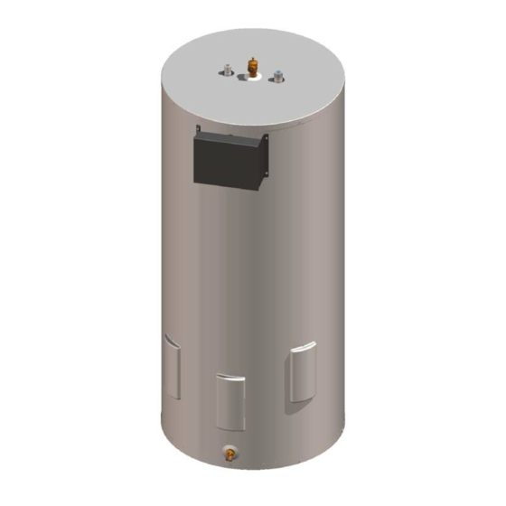
Page 36: Generic Parts List
Generic Parts List 1. Hot Water Outlet Anode 8. Terminal Block 2. T&P Relief Valve 9. Brass Drain Valve 3. Cold Water Inlet Dip Tube 10. Thermostat Mounting Bracket 4. Control Box 11. Element Gasket 5. Ground Lug 12. Heating Element 6. - Page 38 Email parts@bradfordwhite.com techserv@bradfordwhite.com www.bradfordwhite.com...
Need help?
Do you have a question about the ELECTRIC WATER HEATER and is the answer not in the manual?
Questions and answers