Table of Contents
Advertisement
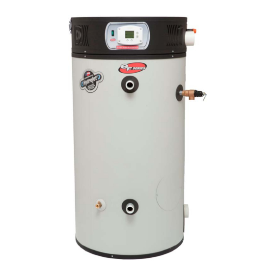
The Bradford White
Ultra High Efficiency Water Heaters
SERVICE
MANUAL
Troubleshooting Guide
and Instructions for Service
(To be performed ONLY by
qualified service providers)
For the Bradford White
eF Series
®
Ultra High
Efficiency Models:
EF60T125E*(NA,XA)(2)
EF60T150E*(NA,XA)(2)
EF60T199E*(NA,XA)(2)
EF100T150E*(NA,XA)(2)
EF100T199E*(NA,XA)(2)
EF100T250E*(NA,XA)(2)
EF100T300E*(NA,XA)(2)
(*) Denotes Warranty Years
Manual 45817A
Save this manual for future reference
Advertisement
Table of Contents

Related Manuals for Bradford White EF Series


Summary of Contents for Bradford White EF Series
- Page 1 The Bradford White Ultra High Efficiency Water Heaters SERVICE MANUAL Troubleshooting Guide and Instructions for Service (To be performed ONLY by qualified service providers) For the Bradford White eF Series ® Ultra High Efficiency Models: EF60T125E*(NA,XA)(2) EF60T150E*(NA,XA)(2) EF60T199E*(NA,XA)(2) EF100T150E*(NA,XA)(2) EF100T199E*(NA,XA)(2)
-
Page 2: Table Of Contents
The Bradford White The Bradford White Ultra High Efficiency Water Heaters Ultra High Efficiency Water Heaters Table of Contents Page eF Service Procedure Introduction - - - How to use this manual - - - Tool required for service - - -... -
Page 3: Introduction
Heater. ® The Bradford White eF Series Ultra High Efficiency Water Heater uses a low Nox premix power burner located at the top of the water heater to direct a turbulent flame down into a submerged combustion chamber. This turbulence causes a thorough mixing of gas and air for optimum combustion. -
Page 4: How To Use This Manual
It is intended for this manual to be used by qualified service personal for the primary purpose of ® troubleshooting analysis and repair of the Bradford White eF Series Ultra High Efficiency Water Heater. Understanding the sequence of operation section of this manual will contribute greatly to troubleshooting this product. -
Page 5: Specifications
Specifications Recovery GPH Recovery GPH DIMENSIONS (INCHES) DIMENSIONS (INCHES) at Degree Rise at Degree Rise Front Space Input Therm T&P Shpg Flr to Flr to Flr To Heating Model No Rate 40°F 100°F 140°F Flr. To Flr to Conn Valve U.S. - Page 6 Specifications Power supply Dedicated 120 VAC, 60 Hz, 15A, GFI Gas Supply Minimum ¾" NPT (schedule 40 black iron pipe recommended) Approved Gas Type Natural or Propane. Unit must match gas type supplied. Gas Pressure ( 14.0" W.C. maximum static, 4.5" W.C. minimum running (recommend 7.0" W.C. min running) Nat &...
- Page 7 Specifications Vent Tables Balanced Direct Vent Systems Power Vented Systems PVC, CPVC or ABS PVC, CPVC or ABS Total length of intake piping and exhaust Total length of exhaust piping must not piping added together must not exceed exceed “Maximum Vent Length” “Maximum Combined Length”...
-
Page 8: Sequence Of Operation
Sequence of Operation Thermostat calls for heat. -Prior to energizing blower, ignition module checks safety circuits for normal switch positions: a) Vent temp switch normally closed. b) Intake pressure switch normally closed. c) Exhaust pressure switch normally open. If the vent temp switch is open, the control waits indefinitely for temp switch to close. If the exhaust pressure switch contacts are closed (not in normal position), the ignition module will wait 45 seconds for pressure switch contact to open before energizing blower. - Page 9 Sequence of Operation Lockout Conditions The system will go into lock out mode for the following reasons: -Pressure switches stuck open or closed. a) Check for exhaust or intake obstructions. b) Check for compliance with vent tables. c) Check for evidence of moisture or condensate present in pressure switch tubing or pressure switch. -No ignition after 3 attempts.
-
Page 10: Troubleshooting
Troubleshooting Troubleshooting Troubleshooting System Observation System Observation System Observation WARNING WARNING WARNING Is front panel power Position front panel 120 volt potential exposure. Use caution Is front panel power Position front panel Is front panel power Position front panel 120 volt potential exposure. Use caution 120 volt potential exposure. - Page 11 Troubleshooting LED status & probable cause Determine failure mode by observing flashing LED status on ignition module. LED status and probable cause shown below. * Denotes conditions that may require the heater to be isolated from the vent system to determine root cause.
-
Page 12: Thermostat Circuit, Testing & Replacement
SERVICE PROCEDURE EF-I SERVICE PROCEDURE EF-I Thermostat Circuit Testing and Replacement Thermostat Circuit Testing and Replacement IMPORTANT NOTE: This procedure assumes a cool tank IMPORTANT NOTE: This procedure assumes a cool tank WARNING WARNING 120 volt potential exposure. Use Rotate temperature Rotate temperature 120 volt potential exposure. - Page 13 SERVICE PROCEDURE EF-I Thermostat Circuit Testing and Replacement APPENDIX - A Sensor Resistance at Various Temperatures Be Careful When Making Voltage Measurements or Jumping Terminals Not to Damage or Deform Connectors or Connector Pins. Draw Water From The T&P Valve. Compare Temperature With Temperature Ohms Chart Below.
- Page 14 SERVICE PROCEDURE EF-I Thermostat Circuit Testing and Replacement WARNING Thermostat circuit. (continued from page 12) 120 volt potential exposure. Use caution making voltage checks to avoid personal injury. Check AC source to determine why there is no power. Replace ignition module. (see pg 34) Refer to ignition module Refer to ignition module...
- Page 15 SERVICE PROCEDURE EF-I SERVICE PROCEDURE EF-I Thermostat Circuit Testing and Replacement Thermostat Circuit Testing and Replacement Thermostat Board Replacement Procedure Thermostat Board Replacement Procedure Step 1. Position main power switch to “OFF” Step 1. Position main power switch to “OFF” WARNING WARNING 120 volt potential exposure.
- Page 16 SERVICE PROCEDURE EF-I Thermostat Circuit Testing and Replacement Thermostat Potentiometer Replacement Procedure Step 1. Position main power switch to “OFF” WARNING 120 volt potential exposure. Isolate the Step 2. Disconnect (unplug) water heater from appliance and reconfirm power is 120 volt power source. disconnected using a multi-meter.
- Page 17 SERVICE PROCEDURE EF-I Thermostat Circuit Testing and Replacement Thermostat Sensor (Thermister) Replacement Procedure Step 1. Position main power switch to “OFF” WARNING Step 2. Disconnect (unplug) water heater from 120 volt potential exposure. Isolate the 120 volt power source. appliance and reconfirm power is disconnected using a multi-meter.
-
Page 18: Combustion System Testing And Replacement
SERVICE PROCEDURE EF-II Combustion System Testing and Replacement Observe burner operation through the sight glass located on the combustion insert mounting flange. Normal burner operation should ignite smoothly, without evidence of coughing or huffing upon ignition. The burner flame should be a blue flame near the burner surface in a uniform flame pattern. Occasional yellow or white streaks are normal. - Page 19 SERVICE PROCEDURE EF-II SERVICE PROCEDURE EF-II Combustion System Testing and Replacement Combustion System Testing and Replacement Observe burner operation through the sight glass located on the combustion insert mounting flange. Observe burner operation through the sight glass located on the combustion insert mounting flange. Normal burner operation should ignite smoothly, without evidence of coughing or huffing upon Normal burner operation should ignite smoothly, without evidence of coughing or huffing upon ignition.
- Page 20 SERVICE PROCEDURE EF-II Combustion System Testing and Replacement WARNING Heater components may be HOT when performing the following steps in this procedure. Take necessary precaution to prevent personal injury. Combustion System Removal Procedure Step 1. Position main power switch to “OFF”. WARNING 120 volt potential exposure.
- Page 21 SERVICE PROCEDURE EF-II Combustion System Testing and Replacement Combustion System Replacement Procedure Step 1. Fully inspect burner mounting insert gasket for the following: a) Tears d) Dirt or debris b) Missing material e) Other imperfections that would inhibit proper seal c) Cracks If gasket is NOT affected by any of the above, gasket replacement is not required.
-
Page 22: Burner Tube Inspection & Replacement
SERVICE PROCEDURE EF-III Burner Tube Inspection and Replacement WARNING Heater components may be HOT when performing the following steps in this procedure. Take necessary precaution to prevent personal injury. Burner Tube Removal Procedure WARNING Step 1. Position main power switch to “OFF”. 120 volt potential exposure. - Page 23 SERVICE PROCEDURE EF-III Burner Tube Inspection and Replacement WARNING Heater components may be HOT when performing the following steps in this procedure. Take necessary precaution to prevent personal injury. Burner Tube Inspection Step 1. Inspect burner tube as follows: a) Visually inspect ceramic fiber mesh, mesh should be uniform in appearance without large gaps, tears or fraying.
-
Page 24: Gas Valve Replacement
Service Procedure EF-IV Gas Valve Replacement Gas Valve Replacement Procedure WARNING Step 1. Position main power switch to “OFF”. 120 volt potential exposure. Isolate the Step 2. Disconnect (unplug) water heater from appliance and reconfirm power is 120 volt power source. disconnected using a multi-meter. -
Page 25: Blower Testing And Replacement
Service Procedure EF-V Blower Testing and Replacement Is there a minimum of Refer to ignition module 98VAC across the Replace Does blower illustration. white and black wires ignition module. energize? Is there 120VAC between at the terminal block ? (see pg 34) P5(1) and P5(3)? (see photo 17) Determine... - Page 26 Service Procedure EF-V Blower Testing and Replacement Blower Replacement Procedure WARNING Step 1. Position main power switch to “OFF”. 120 volt potential exposure. Isolate the appliance and reconfirm power is Step 2. Disconnect (unplug) water heater from disconnected using a multi-meter. 120 volt power source.
-
Page 27: Exhaust Pressure Switch Testing And Replacement
Service Procedure EF-VI Service Procedure EF-VI Exhaust Pressure Switch Testing and Replacement Exhaust Pressure Switch Testing and Replacement Sequence of operation: Sequence of operation: With the thermostat calling for heat, prior to energizing blower, the ignition module checks the exhaust pressure switch for normal With the thermostat calling for heat, prior to energizing blower, the ignition module checks the exhaust pressure switch for normal switch position of normally open. - Page 28 Service Procedure EF-VI Exhaust Pressure Switch Testing and Replacement Check Collector Pressure Check exhaust collector pressure at the exhaust collector pressure tap location (see illustration below). Is there positive pressure equal to or greater than pressure switch settings below? With monometer, take a reading at the exhaust EXHAUST PRESSURE SWITCH SETTINGS Is exhaust venting...
- Page 29 Service Procedure EF-VI Exhaust Pressure Switch Testing and Replacement Exhaust Pressure Switch Replacement Procedure Step 1. Position main power switch to “OFF” position. Step 2. Loosen adhesive backed rubber escutcheon from service panel access cover and slide escutcheon back along exhaust pipe to allow for removal of cover. Rubber escutcheon Step 3.
-
Page 30: Hot Surface Ignitertesting And Replacement
Service Procedure EF-VII Hot Surface IgniterTesting and Replacement Hot surface Igniter Testing Procedure WARNING 120 volt potential exposure. Use caution making voltage checks to avoid personal injury. Refer to ignition module illustration below, Is igniter resistance is there 120VAC across terminals less than 150 Ohms Check harness P6(1) and P6(2)? - Page 31 Service Procedure EF-VII Hot Surface IgniterTesting and Replacement Hot surface Igniter Replacement Procedure Step 1. Position main power switch to “OFF” WARNING Step 2. Disconnect (unplug) water heater 120 volt potential exposure. Isolate the from 120 volt power source. appliance and reconfirm power is disconnected using a multi-meter.
-
Page 32: Flame Sensor Testing And Replacement
Service Procedure EF-VIII Service Procedure EF-VIII Flame Sensor Testing and Replacement Flame Sensor Testing and Replacement Flame Sensor Testing Procedure Flame Sensor Testing Procedure WARNING WARNING 120 volt potential exposure. Use caution 120 volt potential exposure. Use caution making voltage checks to avoid making voltage checks to avoid personal injury. - Page 33 Service Procedure EF-VIII Flame Sensor Testing and Replacement Flame Sensor Replacement Procedure Step 1. Position main power switch to “OFF” WARNING Step 2. Disconnect (unplug) water heater 120 volt potential exposure. Isolate the from 120 volt power source. appliance and reconfirm power is disconnected using a multi-meter.
-
Page 34: Ignition Module Replacement
Service Procedure EF-IX Ignition Module Replacement Ignition Module Replacement Procedure WARNING Step 1. Position main power switch to “OFF”. 120 volt potential exposure. Isolate the appliance and reconfirm power is Step 2. Disconnect (Unplug) water heater disconnected using a multi-meter. from 120 Volt power source. -
Page 35: Transformer Replacement
Service Procedure EF-X Transformer Replacement Transformer Replacement Procedure Step 1. Position main power switch to “OFF”. WARNING 120 volt potential exposure. Isolate the Step 2. Disconnect (Unplug) water heater appliance and reconfirm power is from 120 Volt power source. disconnected using a multi-meter. Step 3. -
Page 36: Intake Pressure Testing And Replacement
Service Procedure EF-XI Intake Pressure Switch Testing and Replacement WARNING 120 volt potential exposure. Use caution making voltage checks to avoid personal injury. Is there continuity through the normally Replace closed intake pressure intake pressure switch. Does Blower Energize? switch? (see pg 37) (see photo 31) See Vent Safety Switch (page 38) - Page 37 Service Procedure EF-XI Intake Pressure Switch Testing and Replacement Intake Pressure Switch Replacement Procedure WARNING Step 1. Position main power switch to “OFF”. 120 volt potential exposure. Isolate the appliance and reconfirm power is Step 2. Disconnect (Unplug) water heater disconnected using a multi-meter.
-
Page 38: Vent Safety Switch Testing And Replacement
Service Procedure EF-XII Vent Safety Switch Testing and Replacement Sequence of operation: With the thermostat calling for heat, prior to energizing blower, the ignition module checks the vent safety switch for normal switch position of normally closed. If the vent safety switch contacts are open, (not in normal position), the ignition module waits indefinitely for contact to close, The vent safety switch must be manually reset to close the switch contacts. - Page 39 Service Procedure EF-XII Service Procedure EF-XII Vent Safety Switch Testing and Replacement Vent Safety Switch Testing and Replacement Vent Safety Switch Replacement Procedure Vent Safety Switch Replacement Procedure Step 1. Position main power switch to “OFF”. Step 1. Position main power switch to “OFF”. Step 2.
-
Page 40: Anode/Flue Baffle Inspection And Replacement
Service Procedure EF-XIII Anode/Flue Baffle Inspection and Replacement Disassembly Procedure for Access to Anodes & Flue Baffles WARNING Heater components may be HOT when performing the following steps in this procedure. Take necessary precaution to prevent personal injury. WARNING Step 1. Position main power switch to “OFF”. 120 volt potential exposure. - Page 41 Service Procedure EF-XIII Anode/Flue Baffle Inspection and Replacement Anode inspection and replacement WARNING Heater components and stored water may be HOT when performing the following steps in this procedure. Take necessary precaution to prevent personal injury. Step 1. Turn off water supply and drain water heater. Step 2.
- Page 42 Service Procedure EF-XIII Anode/Flue Baffle Inspection and Replacement Flue baffle inspection and replacement WARNING Heater components may be HOT when performing the following steps in this procedure. Take necessary precaution to prevent personal injury. Step 1. Disassemble heater per disassembly procedure on page 40. Step 2.
- Page 43 Service Procedure EF-XIII Anode/Flue Baffle Inspection and Replacement Collector Cover Installation Procedure Step 1. Remove old silicone from top surface of collector flange and collector cover. Step 2. Apply ¼" bead of Ultra Copper Silicone around entire collector flange surface. Step 3.
-
Page 44: Installation Check List
® eF Series Heater Installation Check List Product Handling - Carefully uncrate the heater. Move in place with a hand truck (Do not use the venting pipes for handles). Electrical Requirements - Make sure there is 120 volts line voltage. Line voltage must be properly polarized. - Page 45 ® eF Series Heater Service Report Date Service Provider Model Number Phone Number Serial Number Venting (PVC, CPVC,ABS): Vent size 3" or 4" Length of straight pipe (intake) Intake 90's (qty) Intake 45's (qty) Length of straight Exhaust 90's (qty)
-
Page 46: Parts List
Parts List Combustion surround assy. Burner assy pass top collector cover Screw 10-16 x 3/4 Vent termination elbow Thermostat sensor probe Baffle 4" flue Mag rod Baffle 2" flue Wire harness service panel Plastisert nipple 1-½" NPT Plug Nipple T&P relief valve Exhaust pipe (PVC) w/Hose barb Condensate trap elbow Silicone hose... - Page 47 Parts List Latch assy Screw 8-32 x ½ RHCR Ignition control assy Jacket Head Main power switch Potentiometer Combustion surround Surround base Combustion surround assy. Blower gas valve assy Burner assy Blower EBM Silicone hose Hose tee fitting Screw 10-32 x3/4 Gasket &...
- Page 48 Parts List Electronic control module Screw 8-32 x 1/2 Intake pressure switch Control mounting panel Thermostat PC board Transformer 120VAC x 24VAC x 40VA Terminal Terminal strip Power cord 10C Control wire harness 11C Thermostat wire harness 12C Igniter extension wire 13C Blower wire harness 14C Power switch wire harness 15C Flame sensor wire harness...
-
Page 49: Glossary Of Terms
Glossary of Terms Alternating Current BTU/H British Thermal Units Carbon Monoxide Carbon Dioxide Direct Current Energy Cut Off Ground fault interrupt Gallons per Minute Hot Surface Igniter Hertz Light Emitting Diode Oxides of Nitrogen National Pipe Thread Pounds per Square Inch Revolutions per Minute Volt Amps Volts Alternating Current... - Page 50 NOTES Page 50 Page 50...
- Page 51 NOTES Page 51 Page 51...
- Page 52 Email parts@bradfordwhite.com techserv@bradfordwhite.com www.bradfordwhite.com www.bradfordwhitecanada.com...
Need help?
Do you have a question about the EF Series and is the answer not in the manual?
Questions and answers