
Related Manuals for V-fit KP2071


Summary of Contents for V-fit KP2071
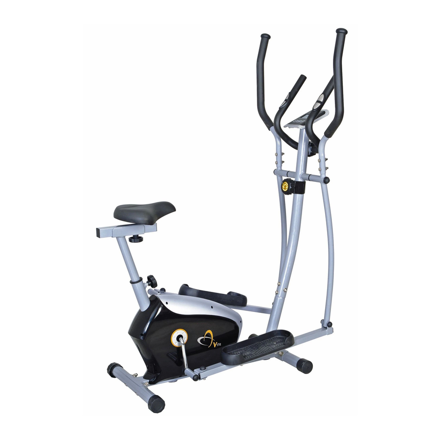
- Page 1 KP2071 - UK KPCE-12/1 COMBINATION 2 IN 1 MAGNETIC CYCLE-ELLIPTICAL TRAINER Assembly & User Manual Please ensure that you read this manual carefully before attempting to assemble or use your new product and retain for future use...
-
Page 3: Table Of Contents
Contents Section Page General Information ..4 Before You Start ..5 Safety ....6 Exercise Information . -
Page 4: General Information
General Information Quality Guarantee This exercise product has been designed and This product is guaranteed for DOMESTIC USE ONLY for manufactured to comply with the latest (BS EN 957) a period of 1 YEAR from the original certified date of British and European Safety Standards. -
Page 5: Before You Start
Before you Start Tools If required, most of our products are supplied with basic tools, which will enable you to successfully assemble your product. However, you may find it beneficial to have a soft-headed hammer and perhaps an adjustable spanner handy as this may help. Prepare the Work Area It is important that you assemble your product in a clean, clear, uncluttered area. -
Page 6: Safety
Safety Before you undertake any programme of exercise that will increase cardiovascular activity please be sure to consult with your doctor. Frequent strenuous exercise should be approved by your doctor and proper use of your product is essential. Please read this manual carefully before commencing assembly of your product or starting to exercise. -
Page 7: Exercise Information
Exercising Information Beginning How you begin to exercise will vary from person to person. If you have not exercised for a long period of time, have been inactive for a while, or are severely overweight you MUST start slowly, increasing your exercise time gradually, by perhaps only a few minutes for each session per week. - Page 8 Exercising Information Warm Up A successful exercise programme consists of three parts, Warm Up, Aerobic Exercise and Cool Down. Never start a training session without warming up. Never finish one without cooling down correctly. Perform between five and ten minutes of stretching before starting your workout to prevent muscle strains, pulls and cramps.
-
Page 9: Cool Down
Exercising Information Target Zone (con't) USERS UNCONDITIONED CONDITIONED TARGET ZONE - A TARGET ZONE - B (Years) (Beats per Minute) (Beats per Minute) 20-24 145 - 165 155 - 175 25-29 140 - 160 150 - 170 30-34 135 - 155 145 - 165 35-39 130 - 150... - Page 10 Exercising Information Shoulder Lif t Rotate and lift your right shoulder up towards your ear for one count. Relax then repeat for the left shoulder. Repeat 3 - 4 times. Calf / Achilles Stretch Turn towards the wall and place both hands on it. Support yourself with one leg while the other is placed behind you with the sole flat on the floor.
- Page 11 Exercising Information Basic Aerobic Training Programme For your basic Aerobic Exercise routine we suggest that you try the following. Remember, breathe correctly, exercise at your own pace and do not over-train as injury may result. Week 1 & 2 Exercise 4 minutes at 'A' Rest 1 minute Warm Up 5 - 10 Minutes Exercise 2 minutes at 'A'...
-
Page 12: Monitor Function Specifications
EXERCISE MONITOR USER INSTRUCTIONS Your Exercise Monitor has been specially designed to help you plan and view your exercise performance. EXERCISEMONITORFUNCTIONS SPEED ~ (CYCLE SPEED [KM/H]) DISTANCE ~ (EXERCISE DISTANCE [KM]) TIME ~ (COUNT UP [Minutes and Seconds]) CALORIES ~ (COMPUTED THEORETICAL CALORIE BURN) PULSE ~ (ACTUAL EXERCISE PULSE RATE) MONITOR FUNCTION SPECIFICATIONS... - Page 13 Computer Monitor Instruction EXERCISE MONITOR CABLE CONNECTION In most cases where there is an apparent failure of your Exercise Monitor to work, it is due to incorrect fitment of the Exercise Monitor cable connections. So, please ensure that there is NO GAP between the connectors on the Exercise Monitor cables when finally assembled.
-
Page 14: Assembly & Adjustments
Assembly & Adjustments OPERATING ADJUSTMENTS and GENERAL USER INFORMATION Note LEVELLING THE CYCLE/CROSS TRAINER For security and stability, your Magnetic Cycle/Elliptical Trainer has Incorrect or excessive a factory welded frame and once fully assembled correctly, should training may damage your not need further alignment. - Page 15 Assembly & Adjustments LUBRICATION and MAINTENANCE The moving pa rts in your Magnetic Cycle/Elliptical Trainer are all pre-lubricated at assembly and should not require further attention. We recommend however that the trainer is used inside and stored in a dry condition. To clean the metal and plastic components, a general household cleaner can be used, but please be sure to dry the trainer and any attachments before use.
-
Page 16: Assembly
Assembly ACCESSORY FITMENT LIST These are all the accessories you will need to complete the assembly of your product. The following accessories are supplied in a pack and should be checked before attempting assembly. Item 34 Item 31 Item 41 Item 42L/R Item 35 Item 32... - Page 17 Assembly Carefully unpack each component, checking against the parts list that you have all the necessary parts to complete the assembly of your product. Please note that some of the parts may be pre-fitted to major Beny Sports Co. UK Ltd components, so please check carefully before contacting our Unit 8, Riparian Way, CUSTOMER SUPPORT team.
- Page 18 Assembly A-1.Hold the Tension Cable (19) below the metal bracket. Guide the lower part of the INNER Cable of the Tension Control Knob (17) into the formed metal loop on the INNER Cable of the Tension Cable. A-2.Still holding the Tension Cable (19), pull the Tension Control Knob INNER Cable (17) away from the Metal Bracket (you will notice some resistance at this stage) and guide the INNER Cable through the open slot in the Metal Bracket.
- Page 19 Assembly Connect the Footplate Bars (5 L/R ) to the Crankshaft (22) using 1 x Shouldered Bolt (38 L/R) 1 x M17 x 30mm Wavy Washer (62) throughthe Footplate Support Bar Pivot Bracket and into the Crankshaft, then fit 1 x M13 Spring Washer (41) and 1 x M13 Nylon Locknut (42 L/R) for each side to secure the complete assembly.
- Page 20 Assembly Remove the 2 x M8 x 30mm Allen Bolts (51) and 2 x M8 Spring Washers (52) from the front of the Handlebar Upright (2). Attach the Fixed Handbar (8) to the Handlebar Upright (2) Using 2 x M8 x 30mm Allen Bolts (51), 2 x M8 Spring Washers (52).
- Page 21 Assembly Fit the Saddle Stem Support to the Saddle Post (72) and secure using 1 x M8 Flat Washer (75) and 1 x M8 x 20mm Locking Knob (74). Then insert the Saddle Post (72) to the Main Frame (1) using 1 x M16 Adjust Knob (80).
- Page 22 Assembly Page 22...
- Page 23 Assembly MASTER PARTS & ACCESSORY LIST PART No. DESCRIPTION ....QTY S19 Nut Cap ....Main Frame .
-
Page 24: Customer Support
Beny Sports Co. UK Ltd. Unit 8, Riparian Way, The Crossings, Cross Hills, West Yorkshire BD20 7BW CUSTOMER SUPPORT is open from 9.00am to 5.00pm from Monday to Friday Tel: 01535 637711 Fax: 01535 637722 E-mail: support@benysports.co.uk Copyright BSCL 2012 Printed August / 2012...
Need help?
Do you have a question about the KP2071 and is the answer not in the manual?
Questions and answers