
Related Manuals for Audiovox AVXMTG13UA


Summary of Contents for Audiovox AVXMTG13UA
-
Page 1: Installation Guide
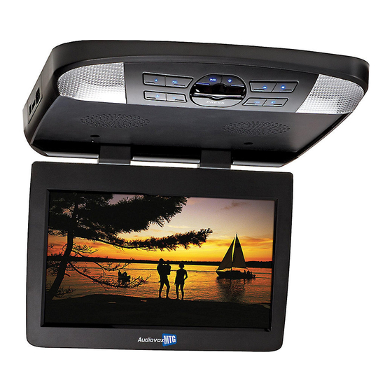
13.3 -Inch LED Backlit LCD Roof-Mount DVD Player With DVD/CD/MP SYSTEM 13UA AVXMTG INSTALLATION GUIDE... -
Page 3: Table Of Contents
Installing the Trim Ring �������������������������������������������������������������������������������������������������������������������������������������������������������������������������������������������������������������������������������������������������������������8 General Vehicle Installation Approach ��������������������������������������������������������������������������������������������������������������������������������������������������������������������������������������������������������������������������������9 Vehicle Preparation ������������������������������������������������������������������������������������������������������������������������������������������������������������������������������������������������������������������������������������������������������������������ 10 Connecting the Dome Lights ����������������������������������������������������������������������������������������������������������������������������������������������������������������������������������������������������������������������������������������������� 11 Installing the Mounting Bracket ����������������������������������������������������������������������������������������������������������������������������������������������������������������������������������������������������������������������������������������� 13 Wiring the AVXMTG13UA Video System �������������������������������������������������������������������������������������������������������������������������������������������������������������������������������������������������������������������������� 14 Installing the AVXMTG13UA Video System ��������������������������������������������������������������������������������������������������������������������������������������������������������������������������������������������������������������������� 15 Troubleshooting ����������������������������������������������������������������������������������������������������������������������������������������������������������������������������������������������������������������������������������������������������������������������� 16... -
Page 4: Important Notices
Enjoy your AUDIOVOX entertainment system but remember that the safety of all An LCD panel and/or video monitor used for television reception, passengers remains the number one priority�... -
Page 5: Ir Transmit And Receive Modes (M1 Or M2)
M2 mode� To change from M1 to M2 mode, point the remote control towards the IR receiver on the AVXMTG13UA� Press and hold the M2 button for 5 to 7 seconds� The following screen will be displayed: Note: The OSD will appear on the screen for 4 –... -
Page 6: Materials Included In This Package
(1 pc) *Note: The AVXMTG13UA is supplied with a black snap-on shroud and screen cover� To install the pewter or shale snap-on shroud or screen cover, the black snap-on shroud and screen cover must be removed first� See the following page for the removal process�... -
Page 7: Removing And Installing Snap On Covers And Shroud
REMOVING AND INSTALLING SNAP-ON COVERS AND SHROUD Preparation Place the unit on a soft surface to avoid damaging the plastic� Materials Required Snap On-Shroud 13�3” Overhead LCD Snap On-Cover Pry Tool Monitor with DVD Player Disconnecting the Screen Cover “C” “B”... - Page 8 Installing the Screen Cover “D” “D” “D” “D” 1� Open the LCD screen� 2� Hook the two tabs “D” at the bottom edge of the screen cover into the notches on the bottom edge of the LCD screen� 3� Snap the opposite side of the screen cover over the hinges� Disconnecting the Shroud “E”...
- Page 9 Installing the Shroud “F” “F” 1� Open the LCD screen� 2� Slide the shroud over the unit� The shroud will snap into place at locations “F”�...
-
Page 10: Installing The Trim Ring
INSTALLING THE TRIM RING NOTE: The trim rings supplied with this unit are not designed to be trimmed. The trim ring is attached to the video monitor using the perimeter screw bosses� It is important that the screws used in this installation are not over tightened, and that the video monitor and trim ring are mounted in such a way that the assembly does not distort (or bend) when the mounting screws are tightened�... -
Page 11: General Vehicle Installation Approach
1� If it is not certain how the dome lamps tie into the vehicle electrical system, wire the dome lamp circuit (of the DVD overhead) to the driver’s door pin switch� 2� Follow the instructions on page 11 and 12� 3� Contact the Audiovox tech support line if you have any questions regarding dome lamp wiring�... -
Page 12: Vehicle Preparation
• +12v when the key is in the ACC� and run positions� • 0v when the key is OFF� 2� The mounting method and location will vary from vehicle to vehicle, the only focus of this manual is the installation of the AVXMTG13UA and related console accessories�... -
Page 13: Connecting The Dome Lights
CONNECTING THE DOME LIGHTS The dome lights in the video monitor require three connections to the vehicle’s wiring� There are two common types of dome light circuits used, positive switched systems or negative switched systems� Positive switched systems supply voltage to the interior lights to turn ON; negative switched systems apply ground to illuminate the bulbs�... - Page 14 CONNECTING THE DOME LIGHTS Positive Switched Dome Lighting Negative Switched Dome Lighting Red/Black-Lamp on To 3 pin Red/Black-Lamp ON To 3 pin Black/Red-Lamp common connector connector constant Black/Red-Lamp Common Purple/Brown-Lamp Auto +12 VDC on Monitor Purple/Brown-Lamp Auto Fused constant +12 VDC Fused Factory Dome Light Circuit constant...
-
Page 15: Installing The Mounting Bracket
INSTALLING THE MOUNTING BRACKET Installing the Mounting Bracket 1� Once all the pre-wiring is complete, locate: 3� While holding the Mounting Bracket in place, install the • Mounting Bracket (4) M4 x 15mm Self-Drilling Screws� • (4) M4 x 15mm Self-Drilling Screws CAUTION: Be sure that the Self-drilling Screws do not pierce the 2�... -
Page 16: Wiring The Avxmtg13Ua Video System
WIRING THE AVXMTG13UA VIDEO SYSTEM 1� Make the connections to the vehicle for the 12 pin wiring harness 5� Verify all system functions before final mounting of the finished (P/N 112-4126)� assembly� 2� Connect the 2 Pin Power Harness (P/N 112-4129) to vehicle’s... -
Page 17: Installing The Avxmtg13Ua Video System
INSTALLING THE AVXMTG13UA VIDEO SYSTEM Installing the AVXMTG13UA System 1� Make all electrical connections� 2� Attach the AVXMTG13UA unit to the mounting bracket using four M5 screws� Roof Front Headliner Vehicle Mounting Bracket Mounting Bracket Video Unit AVXMTG13UA 4 x M5... -
Page 18: Troubleshooting
TROUBLESHOOTING SYMPTOM: REMEDY: No power at Video Monitor Verify +12 VDC on the Red wire at 2 Pin Power Harness behind the video monitor� Verify a ground connection with a continuity test from a known good ground to the black wire at the 2 Pin Power Harness�... - Page 20 © 2010 AUDIOVOX,150 Marcus Blvd. Hauppauge, NY 11788 2013 AUDIOVOX,150 Marcus Blvd. Hauppauge, NY 11788 128-9214...
Need help?
Do you have a question about the AVXMTG13UA and is the answer not in the manual?
Questions and answers