Table of Contents
Advertisement
Advertisement
Table of Contents

Related Manuals for CTC Union SHDTU03


Summary of Contents for CTC Union SHDTU03
- Page 1 USER MANUAL SHDTU03 NTU/E1...
- Page 3 SHDTU03-NTU/E1 SHDSL Modem Installation and Operation Manual Version 1.1 Revision Date Notes V 1.0 Software: Version: 1.5X7001r-XAT0 V 1.1 2003.10 Auto-configuration added Software: Version 1.19 FW: 2.2...
-
Page 5: Table Of Contents
Table of Contents Chapter 1. Introduction … … … … … ..… … ....I. Features … … … … ...… ..… ...… … … … … … … … … … … … 1-1 II. Specification… … … … … … … … … … … … … … … … … … 1-2 III. - Page 6 Table of Contents Chapter 5. Configuration with Console Port .… ..… . I. Login Procedure … ..… ..… ...… … … … … … … … … … … … 5-1 II. Window structure… … … … .… ...… … … … … … … … … … 5-2 III.
-
Page 7: Chapter 1. Introduction
Chapter 1. Introduction The SHDSL NTU offers two different ways to connect customers to high- speed TDM services with two G.703 E1 interfaces (balance 120 Ohm RJ45 jack or unbalance 75 Ohm dual BNCs). The G.703 interface will carry data at N*64kbps rates (where n=1~32). -
Page 8: Specification
Chapter 1. Introduction Network Interface • Line Rate: SHDSL per ITU G.991.2 • Coding: trellis coded pulse amplitude modulation • Support: ANSI (Annex A) and ETSI (Annex B) • Payload rates: 64kbps to 2.304Mbps (N x 64kbps N=1 to 36) •... -
Page 9: Application
Chapter 1. Introduction... - Page 10 Chapter 1. Introduction This page is left in blank intentionally...
-
Page 11: Front Panel
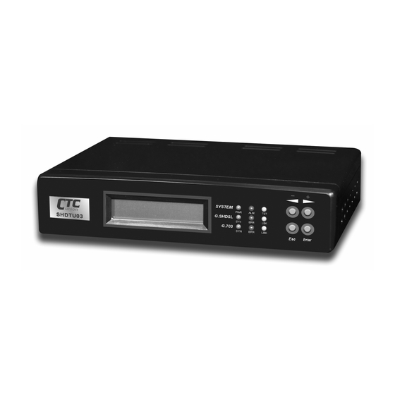
Chapter 2. Hardware Installation This chapter shows the front panel and how to install the hardware. I. Front Panel The front panel contains LED status The LCD can show the status and configuration of the product. The local management interface will be done by push button keys and LCD display. - Page 12 Chapter 2. Hardware Installation The following table describes the LEDs’ function of the SHDTU03. Color Action Description Power is on. Green Power is off. Major alarm occurs. System System is working normally. System is testing for connection. Yellow System is working normally.
-
Page 13: Connector Description
Chapter 2. Hardware Installation From left to right, the rear panel of SHDSL NTU includes the power switch, power socket, RJ-45 console, RJ-45 G.703, BNC jacks for transmitting and receiving and the RJ-45 for SHDSL. Rear Panel with the AC Type Rear Panel with the DC Type Connector Description Power... - Page 14 Chapter 2. Hardware Installation Note: To avoid possible damage to the SHDTU03, do not turn on the product before hardware installation. 1. Plug the power cord in the power socket. 2. Plug the console port in console if you want to configure the NTU with VT100 program of NB or PC.
-
Page 15: Chapter 3. What's Auto Configuration
2~3 mA of current to flow at all times. As with all STU-C type devices, they have the ability to source wetting current. The SHDTU03 will automatically enable wetting current as STU-C type. As STU-R type, it always terminates the wetting current. - Page 16 Chapter 3. What is Auto Configuration This page is left in blank intentionally...
-
Page 17: Purpose
II. How to use key pads The SHDTU03 is designed for user-friendly configuration with keypads and LCD display without using PC or NB with VT100 terminal. Key Pad... -
Page 18: Menu Tree
Chapter 4. Configure via Keypad and LCD III. Menu Tree After turning on the SHDTU03, the LCD will prompt SHDSL NTU (E1). Press Enter to enter. There are five main commands, show status, show statistics, system setup, write configuration and system diagnostic. For more detail, refer to each title. -
Page 19: Menu Tree For Show Status
Chapter 4. Configure via Keypad and LCD Menu tree for SHOW STATUS You can check three kinds of status via LCD display: Type, SHDSL status and E1 status. The SHOW STATUS menu tree is as follows. SHDSL NTU SHOW STATUS TYPE ====(E1)==== STATUS... -
Page 20: Menu Tree For Show Statistic
Chapter 4. Configure via Keypad and LCD Menu tree for SHOW STATISTIC The SHDTU03 can display for current 15 minutes and current 24 hours. The menu tree is as follows. SHDSL NTU SHOW STATISTICS CURRENT 15MIN * SHDSL ES *... -
Page 21: Menu Tree For Setup Type
Chapter 4. Configure via Keypad and LCD Menu tree for SETUP TYPE The menu tree is as follows. SHDSL NTU SYSTEM SETUP * SHDSL TYPE * ====(E1)==== SETUP TYPE STU-R * SHDSL TYPE * STU-C INTCLK * SHDSL TYPE * STU-C EXTCLK SETUP SETUP... - Page 22 Chapter 4. Configure via Keypad and LCD Menu tree for SETUP E1 The route of setup E1 is SHDSL NTU ? SYSTEM SETUP ? SETUP E1. SHDSL NTU SYSTEM SETUP SETUP * E1 CODE * ====(E1)==== SETUP CODE HDB3 * E1 CODE * SETUP * E1 FRAME * FRAME...
-
Page 23: Menu Tree For Save Configuration
Chapter 4. Configure via Keypad and LCD Menu tree for SAVE CONFIGURATION After configuration, the new parameters have to be saved in NVRAM by following these steps. Choose WRITE CONFIGURATION by using L or R key and press Enter. Choose SAVE & REBOOT YES and then press Enter. -
Page 24: Menu Tree For Disgnostic
Chapter 4. Configure via Keypad and LCD Menu tree for DIAGNOSTIC The route for diagnostic is SHDSL NTU ? SYSTEM DIAGNOSTIC ? DIAG LOOPBACK. SHDSL NTU SYSTEM DIAG * LOOPBACK * ====(E1)==== DIAGNOSTIC LOOPBACK DISABLE * LOOPBACK * E1 LINE * LOOPBACK * LOCAL * LOOPBACK *... - Page 25 Check the connectivity of the RS-232 cable from your computer to the console port of SHDTU03. Start your terminal access program with VT100 terminal emulation. Configure the serial link with baudrate of 9600, 8 data bits, no parity check, 1 stop bit, and no flow-control, and press the SPACE key until the login screen appears.
-
Page 26: Window Structure
Chapter 5. Configure via Console Port After you type the password, the SMT displays the main menu. II. Window Structure From top to bottom, the window will be divided into four parts: 1. Product name 2. Menu field: Menu tree is prompted on this field. “ >>” symbol indicates the cursor place. -
Page 27: System Management Terminal(Smt)
Chapter 5. Configure via Console Port III. System Management Terminal (SMT) Menu Commands Before changing the configuration, familiarize yourself with the operations list in the following table. The operation list will be shown on the window. Description Keystroke [UP] or I Move to above field in the same level menu. -
Page 28: Navigating The Smt Interface
Chapter 5. Configure via Console Port Navigating the SMT interface Use the SMT (System Management Terminal) interface to configure the NTU. The following figure is an overview of the menu tree. User Name Setup Type & Password SHDSL annex margin wetting current pwr_backoff framer... -
Page 29: Main Menu Summary
Chapter 5. Configure via Console Port IV. Main Menu Summary The main menu is prompt as follows. Menu Title Function Use this menu to setup SHDSL type, SHDSL parameters and Setup E1 parameters or restore factory default setting. Use this menu to show SHDSL status, E1 status and Status statistics or clear the statistics Use this menu to show general information, all configurations... -
Page 30: Changing The Password And User Profile
Chapter 5. Configure via Console Port V. Changing the password and user profile The SHDSL NTU comes pre-configured with user profile 1 already established, that is, user “ admin” and password “ admin” with menu driven interface. The maximum number of user profile is limited to 5 users. You can add, delete and modify the users in Admin menu. - Page 31 Chapter 5. Configure via Console Port Step 3: Move to modify and press [ENTER] or [RIGHT]. --------------------------------------------------- clear Clear user prof ile modify Modify user profile >> list List user profile --------------------------------------------------- Step 4: The default user name and password is pre-configured in user profile 1.
- Page 32 Chapter 5. Configure via Console Port --------------------------------------------------- Command: admin user modify 1 profile <name> <pass -conf> Message: Please input the following information. Legal user name (Enter for default) <admin>: test Input the old Access password: ***** Input the new Access password: ***** Re-type Access password: ***** ----- - ----------------...
- Page 33 Chapter 5. Configure via Console Port VI. Configure the SHDSL NTU This section provides information about configuring the SHDSL NTU. Follow the procedures: In main menu, select setup and press [ENTER] or [RIGHT]. -------------------------------------------------- setup Configure system >> status Show running system status show View system configuration write...
-
Page 34: Configure Shdsl Type
Chapter 5. Configure via Console Port Configure SHDSL type This section will introduce the configuring of SHDSL type: STU-R, STU- C-INTCLK, STU-C-EXTCLK. The default operation type is STU-R. Select type and press [ENTER] or [RIGHT] to setup SHDSL type. Press [TAB] to select the operating type and press enter to finish setting. -
Page 35: Configure Shdsl Parameters
Chapter 5. Configure via Console Port Configure SHDSL parameters This section provide the setup for SHDSL parameters: Annex type, margin, psd, wetting current, power backoff and framer. Select SHDSL and press [ENTER] or [RIGHT]. -------------------------------------------------- type Configure shdsl type >> shdsl Configure shdsl parameters Setup e1 parameters default... - Page 36 Chapter 5. Configure via Console Port --------------------------------------------------- Command: setup shdsl margin <0~10|Disable> Message: Please input the following information. Set Startup Margin (TAB Select) < 0~10>: Disable ------------------------------------------------------ SNR margin is an index of line connection. You can see the actual SNR margin in STATUS SHDSL.
- Page 37 Chapter 5. Configure via Console Port -------------------------------------------------- Command: setup shdsl psd <r1_asym|r2_asym| sym_enable|asym_disable> Message: Please input the following information. SHDSL PSD (TAB Select) <r1_asym>: r2_asym ------------------------------------------------------ The SHDSL PSD will enable the transceiver to use an asymmetric power spectral density, as specified in the G.991.2 standard. Possible values for PSD are: r1_asym: 786kbps for Annex A, 2312kbps for Annex B r2_asym: 1552kbps for Annex A, 2056kbps for Annex B...
- Page 38 Chapter 5. Configure via Console Port The power backoff of SHDSL is a transmit power negotiation mechanism applied between STU-C and STU-R to limit the power transmitted on the SHDSL line to the minimum necessary for a clear signal to be received at the STU-C. For configuring framer, move the cursor to framer and press [ENTER].
- Page 39 Chapter 5. Configure via Console Port SHDSL V.35 STU-R STU-C (V.35) (E1) Frame N x 64 (N=1~32) V.35 SHDSL STU-R STU-C (E1) (V.35) Frame N x 64 (N=1~32) Time slot, N value, is place of data in the frame. Time Slot Number 1~31 (N=1~31) is Fractional E1 and Time Slot Number 32 (N=32) is unframed.
-
Page 40: Configure E1 Parameters
Chapter 5. Configure via Console Port follow the rule: RULE First Time Slot ? 30 - Time Slot Number First Time Slot ? 30 - Time Slot Number Unframed E1 Time Slot 9 ~ 30 Data Data Data Data Data Data Data Data... - Page 41 Chapter 5. Configure via Console Port >> code Configure e1 code frame Configure e1 frame Configure e1 rai build_outs Configure e1 build outs e_bit Configure e1 e_bit 5-17...
- Page 42 Chapter 5. Configure via Console Port -------------------------------------- ------------- Command: setup e1 code <AMI|HDB3> Message: Please input the following information. SHDSL E1 code (TAB Select) <HDB3>: HDB3 --------------------------------------------------- In this line coding, the transmitter substitutes a deliberate HDB3 bipolar violation when excessive zeros in the data stream are detected.
- Page 43 Chapter 5. Configure via Console Port ---------------------------------------------- --------- Command: setup e1 frame <FAS|FAS+CRC4|FAS+CAS|FAS+CRC4+CAS|UNFRAMED> Message: Please input the following information. SHDSL E1 frame (TAB Select) <fas+crc4+cas>: unframed ------------------------------------------------------- Frame Alignment Signal use 7-bit patterns to establish and maintain frame synchronization. The FAS word is located in timeslot 0 of frame.
- Page 44 Chapter 5. Configure via Console Port CRC4 The CRC-4 checksum bits are transmitted in the outgoing E1 data stream. Also the received signal is checked for errors. CRC-4 checksum cannot be sent in unframed mode. Unframed In this mode, user data is inserted into all 32 channels (64k x 32 = 2048k) of the E1 stream.
- Page 45 Chapter 5. Configure via Console Port Remote Alarm Indication (RAI) is a signal which transmits automatically when E1 line drop. For example: When STU-R E1 RX line is dropped, STU- R will send the status to STU-C via EOC or command. At the same time it will send RAI to DTE.
-
Page 46: Restore Factory Default
Chapter 5. Configure via Console Port For configuring e_bit, move the cursor to e_bit and press [ENTER]. Select the parameter via [TAB] key. ----------------------------------------------------------- code Configure e1 code frame Configure e1 frame Configure e1 rai build_outs Configure e1 build outs >>... -
Page 47: Write The Setup Parameters
Chapter 5. Configure via Console Port VII. Write the Setup Parameter After configuration, write the new configured parameters into NVRAM and reboot the SHDSL NTU to work with new parameters. Follow the procedure; Step 1: In main menu, move the cursor to write and press [ENTER]. -------------------------------------------------------------- setup Configure system... -
Page 48: Reboot The Shdsl Ntu
Chapter 5. Configure via Console Port VIII. Reboot the SHDSL NTU For the SHDSL NTU to work with new parameters, you must reboot it after writing the parameters into NVRAM. Follow the procedure; Step 1: In main menu, move the cursor to reboot and press [ENTER]. ------------------------------------------- ------------------- setup Configure system... -
Page 49: View The System Status
Chapter 5. Configure via Console Port IX. View the System Status You can use the status command to view the status of SHDSL, E1 as well as statistic and clear the statistic log. Select status and press [ENTER]. ------------------------------------------------------------ setup Configure system >>... - Page 50 Chapter 5. Configure via Console Port Select statistic command to show the statistic information in 15 minutes 24 hour via [TAB] to choose. ------------------------------------------------------------ shdsl Show shdsl status Show e1 stat us >> statistic Show statistic clear Clear statistic ------------------------------------------------------------ Command: status statistic <15m|24h>...
-
Page 51: View The System Configuration
Chapter 5. Configure via Console Port X. View the System Configuration You can use the status command to view the system configuration. Select show and press [ENTER] or [RIGHT]. ------------------------------------------------------------ setup Configure system status Show running system status >> show View system configuration write Update flash configuration... -
Page 52: Upgrade The Shdsl Ntu
Chapter 5. Configure via Console Port XI. Upgrade the SHDSL NTU This section will introduce how to upgrade the kernel and FPGA of the SHDSL NTU. Select upgrade in main menu and press [ENTER] or [RIGHT]. ------------------------------------------------------------ setup Configure s ystem status Show running system status show... - Page 53 Chapter 5. Configure via Console Port 3. After entering “ y” , the SMT will show ------------------------------------------------------------ Utility running window... Starting XModem download...CCC ------------------------------------------------------------ 4. Click Send file in terminal access program, hyper terminal, to send the file. 5. Select the source file in window and press OK. 6.
- Page 54 Chapter 5. Configure via Console Port 3. Click Send file in terminal access program, hyper terminal, to send the file. 4. Select the source file in window and press OK. 5. After upgrading the product, press “ y” to write in flash. 5-30...
-
Page 55: Diagnostic
Chapter 5. Configure via Console Port XII. Diagnostic The diagnostic facility allows you to test the different aspects of your SHDSL NTU to determine if it is working properly. Select diag and press [ENTER] or [RIGHT]. ------------------------------------------------------------ setup Configure system status Show running system status show... - Page 56 Chapter 5. Configure via Console Port Loopback Define E1 vs E1 STU-C (E1) STU-R (E1) shdsl shdsl STU-C (E1) STU-R (E1) shdsl shdsl E1_Line Local Remote Line Remote Payload Far End Line Far End Payload Loopback Define Fractional E1 vs V35 STU-C (E1) STU-R (V35) shdsl...
- Page 57 Chapter 5. Configure via Console Port The SHDTU03 supports Bit Error Rate Testing (BERT). To configure the BERT, move the cursor to ber_test and press enter. --------------------------------------------------------- loopback Loopback ber_test Ber_test ------------------------------------------------------------ Command: diag ber_test <disable|2047|resync> Message: Please input the following information.
-
Page 58: Exit Smt
Chapter 5. Configure via Console Port XIII. Exit SMT For exiting SMT without saving any configuration, you can use the exit command to exit the SMT. Select exit and press [ENTER] or [RIGHT]. ------------------------------------------------------------ setup Configure system status Show running system status show View system configuration write... - Page 59 Chapter 5. Configure via Console Port This page is left in blank intentionally 5-35...
- Page 61 APPENDIX Appendix I Alternate mark inversion B8ZS Bipolar 8 zero substitution Also known as timeslot 16 multiframing, requires a multiframe alignment signal to represent for frame sync. CRC4 Cyclic redundancy check 4 bit E BIT GEN Remote End Block Error Bit generation Embedded operations channel Number of Error second (Errors/Second) Extended super frame...
-
Page 62: Connector Architecture
APPENDIX Appendix II Connector Architecture Console Connector (RJ-45) The Console Port interface is a 8 position Modular Jack. The table below displays the pin out assignments. Description Figure Pin Number No connection No connection No connection Front View Top View No connection No connection... - Page 63 APPENDIX G.703 120O Connector (RJ-45) The 120O E1 Port interface is a 8 position modular jack, the following table displays the pin our assignments. Description Pin Number Figure E1 interface receive pair-ring E1 interface receive pair-tip No connection E1 interface transmit pair-ring Front View E1 interface transmit pair-tip Top View...
-
Page 64: Cable Connection
APPENDIX Appendix III Cable Connection DB9 vs. RJ45 Cable (Console) DB9 (Female) RJ-45... - Page 65 APPENDIX...
- Page 66 APPENDIX...
- Page 68 Transmission Units CTC Union Technologies Co., Ltd. Far Eastern Vienna Technologies Center (NeiHu Technology Park) 8F, No. 60, ZhouZi St., NeiHu, Taipei, Taiwan Phone:(886) 2.2659.1021 Fax:(886) 2.2.799.1355 E-mail: info@ctcu.com http://www.ctcu.com...
Need help?
Do you have a question about the SHDTU03 and is the answer not in the manual?
Questions and answers