
Subscribe to Our Youtube Channel
Related Manuals for CTC Union SHDTU03b


Summary of Contents for CTC Union SHDTU03b
-
Page 1: User Manual
USER MANUAL SHDTU03b G.SHDSL.bis Bridge/Router Modems. CTC Union Technologies Co., Ltd. - Page 3 CTC Union Technologies Co., Ltd. Far Eastern Vienna Technology Center (Neihu Technology Park) 8F, No. 60, Zhouzi St. Neihu, Taipei, 114 Taiwan Phone: +886-2-2659-1021 FAX: +886-2-2799-1355 SHDTU03b G.SHDSL.bis Bridge/Router Modem Series User Manual Version 1.0 Nov 2007 Release This manual supports the following models: SHDTU03bF-ET10R Single LAN Port, 2 Wire, G.SHDSL Modem with Firewall...
- Page 4 CTC Union Technologies was negligent regarding the design or manufacture of said product.
-
Page 5: Table Of Contents
TABLE OF CONTENTS DESCRIPTIONS ......................9 ........................9 EATURES ......................9 PECIFICATION ......................11 PPLICATIONS YOUR FIREWALL ......................12 ....................12 YPES OF IREWALL 2.1.1 Packet Filtering ....................12 2.1.2 Circuit Gateway....................14 2.1.3 Application Gateway ..................14 ..................15 ENIAL OF ERVICE TTACK YOUR VLAN (VIRTUAL LOCAL AREA NETWORK) ...........17 ......................17 PECIFICATION ....................17... - Page 6 7.2.5 IPoA or EoA......................34 ADVANCED SETUP......................36 SHDSL.........................36 ........................39 RIDGE VLAN ........................40 .........................41 THERNET ........................42 OUTE NAT/DMZ ........................44 .......................46 IRTUAL ERVER ........................47 IREWALL IP Q S........................52 ADMINISTRATION ......................54 ........................54 ECURITY SNMP ........................55 ........................57 10 UTILITY .........................58 10.1 ......................58 YSTEM 10.2 ......................58 ONFIG...
- Page 7 14.5 ..............67 RIVEN NTERFACE OMMANDS 14.6 .......................67 14.7 ......................69 ONFIGURATION 14.8 ........................70 TATUS 14.9 ........................71 14.10 ........................72 RITE 14.11 .........................73 EBOOT 14.12 ........................74 14.13 ....................75 DMINISTRATION 14.13.1 User Profile ....................75 14.13.2 Security ......................76 14.13.3 SNMP......................76 14.13.4 Supervisor Password and ID ................ 77 14.13.5 SNTP......................77 14.14...
-
Page 9: Descriptions
1. Descriptions The SHDSL.bis (Symmetric High Speed Digital Subscriber Loop) routers comply with G.991.2(2004) standard with 10/100 Base-T auto-negotiation. It provides business-class, multi-range from 192Kbps to 5.696Mbps (for 2-wire mode) payload rates over exiting single-pair copper wire. The SHDSL.bis routers are designed not only to optimize the service bit rate from central office to customer premises also it integrates high-end Bridging/Routing capabilities with advanced functions of Multi-DMZ, virtual server mapping and VPN pass-through. - Page 10 Security DMZ host/Multi-DMZ/Multi-NAT function Virtual server mapping (RFC1631) VPN pass-through for PPTP/L2TP/IPSec tunneling Natural NAT firewall Advanced Stateful packet inspection (SPI) firewall (Firewall Router) Application level gateway for URL and keyword blocking (Firewall Router) User access control: deny certain PCs access to Internet service (Firewall Router) Management Easy-to-use web-based GUI for quick setup, configuration and management Menu-driven interface/Command-line interface (CLI) for local console and Telnet access...
-
Page 11: Applications
LAN: 1, 2, 3, 4 (4-port router) SHDSL.bis: ALM Physical/Electrical Dimensions: 18.7 x 3.3 x 14.5cm (WxHxD) Power: 100~240VAC (via power adapter) Power consumption: 9 watts max Temperature: 0~45。C Humidity: 0%~95%RH (non-condensing) Memory 2MB Flash Memory, 8MB SDRAM Products’ Information G.shdsl.bis 2-wire router/bridge with 1-port LAN G.shdsl.bis 2-wire router/bridge with 1-port LAN VLAN and business class firewall G.shdsl.bis 2-wire router/bridge with 4-port switching hub LAN... -
Page 12: Your Firewall
2 Your Firewall A firewall protects networked computers from intentional hostile intrusion that could compromise confidentiality or result in data corruption or denial of service. It must have at least two network interfaces, one for the network it is intended to protect, and one for the network it is exposed to. A firewall sits at the junction point or gateway between the two networks, usually a private network and a public network such as the Internet. - Page 13 Level 5: Application Protocol Source/Destination address Level 4: TCP Source/destination port IP options Level 3: IP connection status Level 2: Data Link Level 1: Physical Stateful Inspection Filter remember this information 172.16.3.4 192.168.0.5 SP=3264 SA=192.168.0.5 DP=1525 DA=172.16.3.4 Matches outgoing so allows in SP=1525 SA=172.16.3.4 DP=3264...
-
Page 14: Circuit Gateway
PAT (Port Address Translation) Firewall 192.120.8.5 192.168.0.10:1025 192.120.8.5:2205 Internet 192.120.8.5:2206 Client IP Internal Port External Port 192.168.0.10 1025 2205 192.168.0.11:4406 192.168.0.11 4406 2206 Internal/Protected Network External/Unprotected Network 2.1.2 Circuit Gateway Also called a "Circuit Level Gateway," this is a firewall approach that validates connections before allowing data to be exchanged. -
Page 15: Denial Of Service Attack
Level 5: Application Level 4: TCP Telnet Http Level 3: IP SMTP Level 2: Data Link Level 1: Physical Proxy Application Internal External Interface Interface Host PC Public Server Proxy Server Request Page Check URL Request Page Return Page Filter Content Return Page 2.2 Denial of Service Attack Typically, Denial Of Service (DoS) attacks result in two flavors:... - Page 16 Normal reassembled Packets bytes from 1~1500 bytes from 1501~3000 bytes from 3000~4500 Reassembled teardrop packets bytes from 1~1700 bytes from 1300~3200 bytes from 2800~4800 SYN Flood- The attacker sends TCP SYN packets, which start connections very fast, leaving the victim waiting to complete a huge number of connections, causing it to run out of resources and dropping legitimate connections.
-
Page 17: Your Vlan (Virtual Local Area Network)
3 Your VLAN (Virtual Local Area Network) Virtual LAN (VLAN) is defined as a group of devices on one or more LANs that are configured so that they can communicate as if they were attached to the same wire, when in fact they are located on a number of different LAN segments. -
Page 18: Applications
carry user priority information across bridged LANs in which individual LAN segments may be unable to signal priority information (e.g., 802.3/Ethernet segments). 2) The Canonical Format Indicator (CFI) is used to signal the presence or absence of a Routing Information Field (RIF) field, and, in combination with the Non-canonical Format Indicator (NCFI) carried in the RIF, to signal the bit order of address information carried in the encapsulated frame. - Page 19 VID 20 WAN 4 WAN 5 WAN 6 WAN 3 VID 10 VID 30 WAN 2 WAN 7 WAN 8 WAN 1 Backbone Switch SHDSL P OW E R F A U LT D A TA A L A R M Router LAN 1 LAN 2...
-
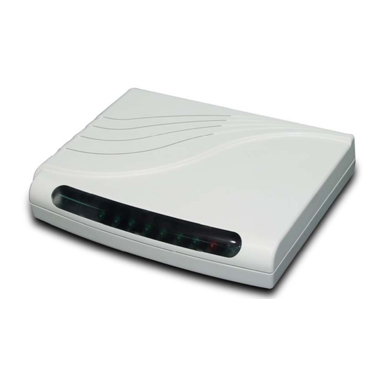
Page 20: Getting To Know Your Router
4 Getting To Know Your Router This section will introduce hardware of the router. 4.1 Front Panel The front panel contains LED which show status of the router. LED status of 4-wire/4-port router LEDs Active Description Power on SHDSL.bis line connection is established Blink SHDSL.bis handshake Transmit or received data over SHDSL.bis link... -
Page 21: Rear Panel
4.2 Rear Panel The rear panel of SHDSL.bis router is where all of the connections are made. Connectors Description of 2-wire/1-port router DC-IN Power adaptor inlet: Input voltage 9VDC Ethernet 10BaseT for LAN port (RJ-45) orLAN (1,2,3,4) 10/100BaseT auto-sensing and auto-MDIX for LAN port (RJ-45) (4-port Router) CONSOLE RS- 232C (DB9) for system configuration and maintenance LINE... -
Page 22: Bis Line Connector
4.3 SHDSL.bis Line Connector 4.4 Console Cable Pin Number Description Fuigure No connection RxD (O) TxD (I) No connection No connection CTS (O) RTS (I) No connection... -
Page 23: Configuration Of The Router
5 Configuration of the router This guide is designed to lead users through Web Configuration of G.shdsl.bis Router in the easiest and quickest way possible. Please follow the instructions carefully. Note: There are three methods to configure the router: serial console, Telnet and Web Browser. Only one configuration application is used to setup the Router at any given time. -
Page 24: Step 5: Install The Shdsl.bis Router
The difference Protocol need to setup difference WAN parameters. After knowing the Ptorocol provided by ISP, you have to ask the necessary WAN parameters to setup it. Bridge EoA Route EoA VPI: VPI: VCI: VCI: Encapsulation: Encapsulation: Gateway: IP Address: Host Name:(if applicable) Subnet Mask: Gateway:... - Page 25 Cross DB-9 Over Cable Ethernet Power Cable Adapter Wall Jack G.shdsl.bis Direct Connection with PC or NB for 1-port router Connection with Hub/Switch for 1-port router Server File Server Workstation Mobile Device HUB/Switch Pass Power Through Wireless LAN Adpater Ethernet G.shdsl.bis Cable Wall Jack...
-
Page 26: Configuration Via Web Browser
6 Configuration via Web Browser Step. 1 For Win85, 98 and Me, click the start button. Select setting and control panel. Step. 2 Double click the network icon. In the Configuration window, select the TCP/IP protocol line that has been associated with your network card and then click property icon. - Page 27 Choose IP address tab. Select Obtain IP address automatically. Click OK button. The window will ask you to restart the PC. Click Yes button. After rebooting your PC, open IE or Netscape Browser to connect the Router. Type http://192.168.0.1 The default IP address and sub net-mask of the Router is 192.168.0.1 and 255.255.255.0.
-
Page 28: Basic Setup
7 Basic Setup The Basic Setup contains LAN, WAN, Bridge and Route operation mode. User can use it to completely setup the router. After successfully completing it, you can access Internet. This is the easiest and possible way to setup the router. Note: The advanced functions are only for advanced users to setup advanced functions. - Page 29 Enter Parameters in BASIC – STEP2: IP: 192.168.0.1 Subnet Mask: 255.255.255.0 Gateway: 192.168.0.254 (The Gateway IP is provided by ISP.) Host Name: SOHO Some of the ISP requires the Host Name as identification. You may check with ISP to see if your Internet service has been configured with a host name.
-
Page 30: Routing Mode
7.2 Routing Mode Routing mode contains DHCP server, DHCP client, DHCP relay, Point-to-Point Protocol over ATM and Ethernet and IP over ATM and Ethernet over ATM. You have to clarify which Internet protocol is provided by ISP. Click ROUTE and CPE Side then press Next. -
Page 31: Dhcp Client
then 1. Lease time 72 hours indicates that the DHCP server will reassign IP information in every 72 hours. DNS Server: Your ISP will provide at least one Domain Name Service Server IP. You can type the router IP in this field. The router will act as DNS server relay function. -
Page 32: Pppoe Or Pppoa
7.2.4 PPPoE or PPPoA PPPoA (point-to-point protocol over ATM) and PPPoE (point-to-point protocol over Ethernet) are authentication and connection protocols used by many service providers for broadband Internet access. These are specifications for connecting multiple computer users on an Ethernet local area network to a remote site through common customer premises equipment, which is the telephone company's term for a modem and similar devices. - Page 33 IP Type: Dynamics. The default IP type is Dynamic. It means that ISP PPP server will provide IP information including dynamic IP address when SHDSL.bis connection is established. On the other hand, you do not need to type the IP address of WAN1. Some of the ISP will provide fixed IP address over PPP. For fixed IP address: IP Type: Fixed IP Address: 192.168.1.1...
-
Page 34: Ipoa Or Eoa
7.2.5 IPoA or EoA IP: 10.1.2.1 Router Netmask: 255.255.255.0 Gateway: 10.1.2.2 IP: 192.168.0.1 DNS: 168.95.1.1 Netmask: 255.255.255.0 IP: 10.1.2.2 Netmask: 255.255.255.0 DSLAM IP: 192.168.0.2~51 VPI:0, VCI:33 Netmask: 255.255.255.0 Encapsulation: LLC Gateway: 192.168.0.1 Before configuration the router, check with your ISP VPI: about this information. - Page 35 The screen will prompt the parameters that will be written in EPROM. Check the parameters before writing in EPROM. Press Restart to restart the router working with new parameters or press continue to setup another parameter.
-
Page 36: Advanced Setup
8 Advanced Setup Advanced setup contains SHDSL.bis, WAN, Bridge, Route, NAT/DMZ, Virtual SERVER and FIREWALL parameters. 8.1 SHDSL.bis You can setup the Annex type, data rate and SNR margin for SHDSL.bis parameters in SHDSL.bis. Click SHDSL.bis Annex Type: There are foure Annex types, Annex A (ANSI), Annex B (ETSI), AnnexAF and Annex BG... - Page 37 The screen will prompt the parameters that will be written in EPROM. Check the parameters before writing in EPROM. Press Restart to restart the router working with new parameters or press continue to setup another parameter. The SHDSL.bis router supports up to 8 PVCs. WAN 1 was configured via BASIC except QoS.
- Page 38 IP and video comferencing, that require tightly constrained delays and delay variation. VBR-rt is characterized by a peak cell rate (PCR), substained cell rate (SCR), and maximun burst rate (MBR). VBR-nrt (Varible Bit Rate non-real-time) PCR (Peak Cell Rate) in kbps: The maximum rate at which you expect to transmit data, voice and video. Consider PCR and MBS as a menas of reducing lantency, not increasing bandwidth.
-
Page 39: Bridge
8.2 Bridge If you want to setup advanced filter function while router is working in bridge mode, you can use BRIDGE menu to setup the filter function, blocking function. Click Bridge to setup. Press Add in the bottom of web page to add the static bridge information. -
Page 40: Vlan
8.3 VLAN Virtual LAN (VLAN) is defined as a group of devices on one or more LANs that are configured so that they can communicate as if they were attached to the same wire, when in fact they are located on a number of different LAN segments. -
Page 41: Ethernet
Port-Based VLANs are VLANs where the packet forwarding decision is based on the destination MAC address and its associated port. Click Port-Based VLAN to configure the router. 8.4 Ethernet This page of function let user configure the media type of Ethernet. Click ETHERNET to configure Ehernet. -
Page 42: Route
8.5 Route If the Router is connected to more than one network, it may be necessary to set up a static route between them. A static route is a pre-determined pathway that network information must travel to reach a specific host or network. With Dynamic Routing, you can enable the Router to automatically adjust to physical changes in the network’s layout. - Page 43 RIP Mode: this parameter determines how the product handle RIP (Routing information protocol). RIP allows it to exchange routing information with other router. If set to Disable, the gateway does not participate in any RIP exchange with other router. If set Enable, the router broadcasts the routing table of the router on the LAN and incoporates RIP broadcast by other routers into it’s routing...
-
Page 44: Nat/Dmz
8.6 NAT/DMZ NAT (Network Address Translation) is the translation of an Internet Protocol address (IP address) used within one network to a different IP address known within another network. One network is designated the inside network and the other is the outside. Typically, a company maps its local inside network addresses to one or more global outside IP addresses and reverse the global IP addresses of incoming packets back into local IP addresses. - Page 45 Multi-NAT: Some of the virtual IP addresses (eg: 192.168.0.10 ~ 192.168.0.50) collectively use two of the global IP addresses (eg: 69.210.1.9 and 69.210.1.10). The Multi-NAT table will be setup as; Virtual Start IP Address: 192.168.0.10 Count: 40 Global Start IP Address: 69.210.1.9 Count: 2 Press Finish to continue.
-
Page 46: Virtual Server
8.7 Virtual Server For example: Specific ports on the WAN interface are re-mapped to services inside the LAN. As only 69.210.1.8 (e.g., assigned to WAN from ISP) is visible to the Internet, but does not actually have any services (other than NAT of course) running on gateway, it is said to be a virtual server. -
Page 47: Firewall
8.8 Firewall A firewall is a set of related programs that protects the resources of a private network from other networks. It is helpful to users that allow preventing hackers to access its own private data resource accidentally. Click Basic Firewall Security. This level only enables the NAT firewall and the remote management security. - Page 48 Click Automatic Firewall Security. This level enables basic firewall security, all DoS protection, and the SPI filter function. Press Finsih to finish setting firewall. The screen will prompt the parameters, which will be written in EPROM. Check the parameters. Press Restart to restart the router or press Continue to setup another function.
- Page 49 resources to be consumed serving the phony requests. A ping of death attack attempts to crash your system by sending a fragmented packet, when reconstructed is larger than the maximum allowable size. Other known variants of the ping of death include teardrop, bonk and nestea.
- Page 50 If you want to ban all of the protocol from the IP (e.g.: 200.1.1.1) to access the all PCs (e.g.: 192.168.0.2 ~ 192.168.0.50) in the LAN, key in the parameter as; Protocol: ANY Direction: INBOUND (INBOUND is from WAN to LAN, and OUTBOUND is LAN to WAN.) Description: Hacker Src.
- Page 51 172.16.1.1:1357 192.168.3.4:25 Internet Firewall SMTP Server SMTP Client Packet Direction Source Destination Protocol Dest. Port Action (Rule) Inbound 10.1.2.3 171.16.3.4 6000 Deny (E) Outbound 171.16.3.4 10.1.2.3 5150 Deny (E) 171.16.3.4:6000 10.1.2.3:5150 Internet X11 Server Firewall Attacker Update Filtering Rule Index Protocol Direction Action Source Destination Source Port Dest.
-
Page 52: Ip Qos
10.1.99.1 172.16.6.1 Permit (A) 10.1.1.1 172.16.6.1 Permit (A) 10.1.1.1 172.16.1.1 Deny (C) 192.168.3.4 172.16.6.1 Deny (C) The rule order will permit 10.1.99.1 to access 172.16.6.1. When the rule is ordered as BAC. Index Source Address Destination Address Action 10.1.99.1 172.16.1.1 Deny (B) 10.1.99.1 172.16.6.1... - Page 53 Set the policy to action. Description: A brief statement describe this policy Local IP: type IP address of local host in prioritized session. Remote IP: type IP address of remote host in prioritized session. Local Port: type the service port number of local host in prioritized session.
-
Page 54: Administration
9 Administration This session introduces security and simple network management protocol (SNMP) and time synchronous. 9.1 Security For system secutiry, suggest to change the default user name and password in the first setup otherwise unauthorized persons can access the router and change the parameters. -
Page 55: Snmp
Configured 0.0.0.0 will allow all hosts on Internet or LAN to access the router. Leaving blank of trust host list will cause blocking all PC from WAN to access the router. On the other hand, only PC in LAN can access the router. - Page 56 SNMP status: Enable Access Right: Deny for deny all access Read for access read only Write for access read and write. Community: it serves as password for access right. After configuring the community pool, press SNMP trap is an informational message sent from an SNMP agent to a manager.
-
Page 57: Time Sync
9.3 Time Sync Time synchronization is an essential element for any business, which relies on the IT system. The reason for this is that these systems all have clock that is the source of timer for their filing or operations. Without time synchronization, these systems’s clocks vary and cause the failure of firewall packet filtering schedule processes, compromised security, or virtual server working in wrong schedule. -
Page 58: Utility
10 Utility This section will describe the utility of the product including: SYSTEM INFO: system information, CONFIG TOOL: load the factory default configuration, UPGRADE: upgrade the firmware LOGOUT: logout the system RESTART: restart the router. 10.1 System Info Click System Info for review the information. The browser will prompt the system information. -
Page 59: Upgrade
10.3 Upgrade You can upgrade the gateway using the upgrade function. Press Upgrade in UTILITY. Browse the file and press OK button to upgrade. The system will reboot automatically after finishing. 10.4 Logout To logout the router, press LOGOUT in UTILITY. 10.5 Restart For restarting the router, click the Restart in UTILITY. -
Page 60: Status
11 Status You can monitor the SHDSL.bis status including mode, Tx power and Bitrate and Performance information including SNR margin, atteunation and CRC error count. LAN status will prompt the MAC address, IP address, Subnet mask and DHCP client table. WAN status will display the WAN interface information. -
Page 61: Lan-To-Lan Connection With Bridge Mode
12 LAN-to-LAN connection with bridge Mode STU-C (CO) STU-R (CPE) Bridge Bridge IP: 192.168.0.1 IP: 192.168.0.2 Netmask: 255.255.255.0 Netmask: 255.255.255.0 VPI:0, VCI:32 Encapsulation: LLC IP: 192.168.0.100 IP: 192.168.0.200 Netmask: 255.255.255.0 Netmask: 255.255.255.0 Gateway: 192.168.0.1 Gateway: 192.168.0.2 12.1 CO side Click Bridge and CO Side to setup Bridging mode of the Router and then click Next. Enter LAN Parameters IP: 192.168.0.1 Subnet Mask: 255.255.255.0... -
Page 62: Cpe Side
12.2 CPE Side Click Bridge and CO Side to setup Bridging mode of the Router and then click Next. Enter LAN Parameters IP: 192.168.0.2 Subnet Mask: 255.255.255.0 Gateway: 192.168.0.2 Host Name: SOHO Enter WAN1 Parameters VPI: 0 VCI: 32 Click LLC Click Next The screen will prompt the new configured parameters. -
Page 63: Lan To Lan Connection With Routing Mode
13 LAN to LAN Connection with Routing Mode STU-C (CO) STU-R (CPE) Router Router IP: 192.168.20.1 IP: 192.168.10.1 IPoA or EoA Netmask: 255.255.255.0 Netmask: 255.255.255.0 VPI:0, VCI:32 Encapsulation: LLC IP: 192.168.30.1 IP: 192.168.30.2 Netmask: 255.255.255.0 Netmask: 255.255.255.0 Gateway: 192.168.30.2 Gateway: 192.168.30.1 IP: 192.168.20.100 IP: 192.168.10.200 Netmask: 255.255.255.0... -
Page 64: Cpe Side
IP Address: 192.168.20.1 Subnet Mask: 255.255.255.0 Gateway: 192.169.30.2 Click Next The screen will prompt the parameters that we will write in EPROM. Check the parameters before writing in EPROM. Press Restart to restart the router working with new parameters or press continue to setup another parameter. 13.2 CPE side Click ROUTE and CPE Side then press Next. -
Page 65: Configuration Via Serial Console Or Telnet With Menu Driven Interface
14 Configuration via Serial Console or Telnet with Menu Driven Interface 14.1 Serial Console Check the connectivity of the RS-232 cable from your computer to the serial port of ROUTER. Start your terminal access program by VT100 terminal emulation with the following parameters: Parameter Value Baudrate... -
Page 66: Window Structure
14.4 Window structure From top to bottom, the window is divided into four parts: Product name Menu field: Menu tree prompts on this field. Symbol “>>” indicates the cursor place. Configuring field: You will configure the parameters in this field. < parameters > indicates the parameters you can choose and <... -
Page 67: Menu Driven Interface Commands
14.5 Menu Driven Interface Commands Before changing the configuration, familiarize yourself with the operations list in the following table. The operation list will be shown on the window. Menu Driven Interface Commands Keystroke Description [UP] or I Move to above field in the same level menu. [DOWN] or K Move to below field in the same level menu. - Page 68 User Name Password Enable Status Show Ping Exit System Enable SHDSL Mode Config Setup Protocol Link Script Mode Status Route Adress N*64 SHDSL Show Interface VPI_VCI Type Write Firewall Encap Clear Bridge Reboot Margin VLAN Ping Class Route Admin IP_type Utility List IP_share...
-
Page 69: Configuration
14.7 Configuration To setup the router, move the cursor “ >>” to enable and press enter key. While the screen appears, type the supervisor password. The default supervisor password is root. The password will be prompted as “ * “ symbol for system security. ---------------------------------------------------------------------- Command: enable <CR>... -
Page 70: Status
14.8 Status You can view running system status of SHDSL.bis, WAN, route and interface via status command. Move cursor “ >> “ to status and press enter. >> shdsl.bis Show SHDSL.bis status Show WAN interface status route Show routing table interface Show interface statistics status firewall... -
Page 71: Show
14.9 Show You can view the system information, configuration and configuration in command script by show command. Move cursor “ >> “ to show and press enter. >> system Show general information config Show all configuration script Show all configuration in command script Command Description system... -
Page 72: Write
14.10 Write For any changes of configuration, you must write the new configuration to EPROM using write command and reboot the router to take affect. Move cursor to “ >> “ to write and press enter. ---------------------------------------------------------------------- Command: write <CR> Message: Please input the following information. -
Page 73: Reboot
14.11 Reboot To reboot the router, use reboot command. Move cursor to “ >> “ to write and press enter. ---------------------------------------------------------------------- Command: reboot <CR> Message: Please input the following information. Do you want to reboot? (y/n): y ----------------------------------------------------------------------... -
Page 74: Ping
14.12 Ping Ping command will be used to test the connection of router. Move cursor “ >> “ to ping and press enter. ---------------------------------------------------------------------- Command: ping <ip> [1~65534|-t] [1~1999] Message: Please input the following information. IP address <IP> : 10.0.0.1 Number of ping request packets to send (TAB select): -t Data size [1~1999]: 32 ----------------------------------------------------------------------... -
Page 75: Administration
14.13 Administration You can modify the user profile, telnet access, SNMP (Sample Network Management Protocol), supervisor information and SNTP (Simple Network Time Protocol) in admin. The route is enable admin. For configuration the parameters, move the cursor “ >> “ to admin and press enter. >>... -
Page 76: Security
14.13.2 Security Security command can be configured sixteen legal IP address for telnet access and telnet port number. Move the cursor “ >> “ to security and press enter. The default legal address is 0.0.0.0. It means that there is no restriction of IP to access the router via telnet. >>... -
Page 77: Supervisor Password And Id
---------------------------------------------------------------------- The screen will prompt as follow: >> edit Edit trap host parameter list Show trap configuration 14.13.4 Supervisor Password and ID The supervisor password and ID are the last door for security but the most important. Users who access the router via web browser have to use the ID and password to configure the router and users who access the router via telnet or console mode have to use the password to configure the router. - Page 78 time_server2 Configure time server 2 time_server3 Configure time server 3 updaterate Configure update period time_zone Configure GMT time zone offset list Show SNTP configuration To configure SNTP v4 time synchronization, follow the below procedures. move the cursor to method and press enter. ---------------------------------------------------------------------- Command: admin sntp method <SNTPv4|SyncWithPC>...
-
Page 79: Utility
Move the cursor to list and review the setting. 14.14 Utility There are three utility tools, upgrade, backup and restore, embedded in the firmware. You can update the new firmware via TFTP upgrade tools and backup the configuration via TFTP backup tool and restore the configuration via TFTP restore tool. -
Page 80: Setup
14.16 Setup All of the setup parameters are located in the subdirectories of setup. Move the cursor “ >> “ to setup and press enter. >> mode Switch system operation mode shdsl.bis Configure SHDSL.bis parameters Configure WAN interface profile bridge Configure transparent bridging vlan Configure virtual LAN paramters... -
Page 81: Wan
Generally, you cannot need to change SNR margin, which range is from 0 to 10. SNR margin is an index of line connection. You can see the actual SNR margin in STATUS SHDSL.bis. The larger is SNR margin; the better is line connection quality. If you set SNR margin in the field as 2, the SHDSL.bis connection will drop and reconnect when the SNR margin is lower than 2. -
Page 82: Bridge
minutes. Most of the ISP use dynamic IP for PPP connection but some of the ISP use static IP. Configure the IP type, dynamic or fixed, via ip_type command. You can review the WAN interface configuration via list command. 14.16.4 Bridge You can setup the bridge parameters in bridge command. -
Page 83: Vlan
14.16.5 VLAN Virtual LAN (VLAN) is defined as a group of devices on one or more LANs that are configured so that they can communicate as if they were attached to the same wire, when in fact they are located on a number of different LAN segments. -
Page 84: Route
tagged members. Use PVID command to change the member port to untagged members To assign PVID (Port VID), move the cursor “>>” to PVID and press enter. The port index 1 to 4 represents LAN1 to LAN4 respectively and port index 5 to 12 represents WAN1 to WAN8. VID value is the group at which you want to assign the PVID of the port. - Page 85 You can add 20 sets of static route entry by using add command. Type the IP information of the static route including IP address, subnet mask and gateway. You can delete the static route information via delete command. You can review the static route entry by using list command. To configure Routing Information Protocol (RIP), you can use rip command to setup the parameters.
-
Page 86: Lan
14.16.8 LAN LAN interface parameters can be configured LAN IP address, subnet mask and NAT network type. >> address LAN IP address and subnet mask attrib NAT network type 14.16.9 IP share You can configure Network Address Translation (NAT), Port Address Translation (PAT) and Demilitarized Zone parameters in ip_share menu. - Page 87 Command: setup ip_share nat virtual range <1~5> <ip> <1~253> Message: Please input the following information. NAT local address range entry number <1~5>: 1 Base address: 192.168.0.2 Number of address: 49 ---------------------------------------------------------------------- You can delete virtual IP address range- from 1 to 5- by using delete command. You can view the virtual IP address range via list command.
-
Page 88: Pat
You can create up to 10 fixed NAT mapping entry via range command. ---------------------------------------------------------------------- Command: setup ip_share nat fixed modify <1~1o> <ip> <ip> Message: Please input the following information. Fixed NAT mapping entry number <1~10>: 1 Local address: 192.168.0.250 Global address: 122.22.22.2 ---------------------------------------------------------------------- After configuration fixed IP address entry, you can bind the entry to specific interface via interface command. -
Page 89: Dmz
Set the active interface number via interface command. You can configure the global port number by using port command. The local server, host, IP address and port number are configured via server command. The authorized access protocol is setup via protocol command. Name command can be used to configure the service name of the host server. -
Page 90: Packet Filtering
There are three level of firewall which you can setup in this product. Level one, basic, only enables the NAT firewall and the remote management security. The NAT firewall will take effect if NAT function is enabled. The remote management security is default to block any WAN side connection to the device. -
Page 91: Ipqos
dos_protection and press enter. >> syn_flood Enable protection SYN flood attack icmp_flood Enable protection ICMP flood attack udp_flood Enable protection UDP flood attack ping_death Enable protection ping of death attack land_attack Enable protection land attack ip_spoff Enable protection IP spoofing attack smurf_attack Enable protection smurf attack fraggle_attack Enable protection fraggle attack... -
Page 92: Dhcp
The add parameters of IPQoS can be configured via add command >> Protocol Configure protocol local_ip Configure local IP parameter remote_ip Configure remote IP parameter Port Configure port parameter description Policy description Enable Enable the policy Precedence Configure precedence parameter The port type is configured by protocol command. -
Page 93: Dns Proxy
>> generic Configure generic DHCP parameters fixed Configure fixed host IP address list list Show DHCP configuration The generic DHCP parameters can be configured via generic command. >> active Tigger DHCP function gateway Default gateway for DHCP client netmask Subnet mask for DHCP client ip_range Dynamic assigned IP address range lease_time... -
Page 94: Host Name
14.16.19 Host name Enter local host name via hostname command. Move cursor “ >> “ to hostname and press enter. ---------------------------------------------------------------------- Command: setup hostname <name> Message: Please input the following information. Local hostname (ENTER for default) <SOHO>: test ---------------------------------------------------------------------- 14.16.20 Default If you want to restore factory default, first move the cursor “... - Page 96 Transmission Series CTC Union Technologies Co., Ltd. Far Eastern Vienna Technology Center (Neihu Technology Park) 8F, No.60, Zhouzi Street Neihu District, Taipei, Taiwan Phone:(886) 2.2659.1021 Fax:(886) 2.2799.1355 E-mail: info@ctcu.com Url:http://www.ctcu.com...
Need help?
Do you have a question about the SHDTU03b and is the answer not in the manual?
Questions and answers