Table of Contents
Advertisement
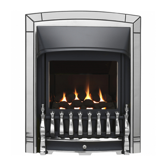
INSTALLER AND OWNER GUIDE
Model 954
Inset live fuel effect gas fire
Incorporating the VALOR FIRES
Fitted with one of the following fascia.
BROOKLYN, CHIC, ENVY, HERITAGE,
LUXOR, MOONLIGHT, OPULENT,
WESTMINSTER SLIMLINE
WILLOUGHBY.
(G.C. Number 32-032-69)
We trust that this guide gives
sufficient details to enable this
appliance to be installed, operated
and maintained satisfactorily.
However, if further information is
required, our
Valor Fires Technical Helpline will
be pleased to help.
Telephone 0844 8711 565 (National
call rates apply in the United
Kingdom).
In the Republic of Ireland
Telephone 0044 844 8711 565.
INSTALLER: Please leave this guide with the owner
©
Baxi Heating U.K. Limited 2010.
CONTROL
or
5132323/02
Advertisement
Chapters
Table of Contents

Related Manuals for Valor Fires 954


Summary of Contents for Valor Fires 954
- Page 1 However, if further information is required, our Valor Fires Technical Helpline will be pleased to help. Telephone 0844 8711 565 (National call rates apply in the United Kingdom).
- Page 2 Warning: Any person who does any unauthorised act in relation to a copyright work may be liable to criminal prosecution and civil claims for damages. Valor Fires, Erdington, Birmingham B24 9QP www.firesandstoves.co.uk Because our policy is one of constant development and improvement, details may vary slightly from...
- Page 3 BS EN ISO 9001 quality system accepted by the British Standards Institute. The Highest Standards Valor Fires is a member of SBGI and HHIC (Heating and Hot water Industry Council) that work to ensure high standards of safety, quality and performance. Careful Installation...
-
Page 4: Installer Guide
INSTALLER GUIDE INSTALLER GUIDE FOR OWNER GUIDE SEE PAGES 50 TO 63 Page 4 © Baxi Heating U.K. Limited 2010. -
Page 5: Table Of Contents
INSTALLER GUIDE CONTENTS Section Page INSTALLER GUIDE 4 - 49 OWNER GUIDE 50 - 63 1. SAFETY AND UNPACKING 2. APPLIANCE DATA AND EFFICIENCY 3. GENERAL INSTALLATION REQUIREMENTS 3.1 Regulations, Standards and Law. 3.2 Ventilation requirements. 3.3 The Atmosphere sensing device (ASD). 3.4 Fireguard requirements. - Page 6 INSTALLER GUIDE CONTENTS (Continued) Section Heading Page 10. BURNER INSTALLATION 10.1 Burner and supply pipe installation. 10.2 Lighting the burner. 10.3 Operating the burner. 10.4 Inlet pressure check. 10.5 Fitting the burner tray trim to the Brooklyn, Chic and Moonlight models. 31 11.
-
Page 7: Safety And Unpacking
INSTALLER GUIDE 1. SAFETY AND UNPACKING Installer Before continuing any further with the installation of this appliance please read the following guide to manual handling. The approximate lifting weight (kg) of this appliance is as below: Model Hotbox and burner assembly Fascia Brooklyn Chic... -
Page 8: Appliance Data And Efficiency
: Model Efficiency % (Gross) 954 when converted to LPG. The gross calorific value of the fuel has been used for this efficiency calculation. The test data from which it has been calculated has been certified by Advantica Certification services (0087). -
Page 9: General Installation Requirements
INSTALLER GUIDE The conversion of net efficiency to gross was achieved by multiplying the net efficiency by the following conversion factor from Table E3 of SAP 2005, rounding down to the nearest whole number. Conversion factor from net to gross efficiency Natural Gas 0.901 0.921... -
Page 10: Ventilation Requirements
INSTALLER GUIDE In the Republic of Ireland the installation must be carried out by a competent person and also conform to the relevant parts of: a) The current edition of IS 813 “Domestic Gas Installations” b) All relevant national and local rules in force. Where no specific instructions are given, reference should be made to the relevant British Standard Code of Practice. -
Page 11: Chimney Preparation
INSTALLER GUIDE 3.6 Chimney preparation. 3.6.1 If the appliance is intended to be installed to a chimney that was previously used for solid fuel, the flue must be swept clean prior to installation. All flues should be inspected for soundness and freedom from blockages. 3.6.2 Any chimney damper or restrictor should be removed. -
Page 12: The Hearth
INSTALLER GUIDE 3.8 The hearth. The appliance must be mounted behind a non-combustible hearth unless the conditions of section 3.10.1.1 are met (N.B. conglomerate marble hearths are considered as non-combustible). The appliance can be fitted to a purpose made proprietary class “O”-150°C surround. The hearth material must be at least 12mm thick. - Page 13 INSTALLER GUIDE Minimum mandatory Recommended Depth clearance to clearance to non- Height Width into Model combustible combustible (mm) (mm) room surfaces projecting surfaces for access (mm) beyond the front of purposes (mm). appliance (mm). Opulent & Luxor Chic & Envy Heritage Westminster Willoughby...
-
Page 14: Installation Options
INSTALLER GUIDE 3.10 Installation options. In the United Kingdom, as supplied, the appliance can be installed in the following situations: - 3.10.1 Conventional fireplace and hearth. To a fireplace complete with hearth as shown in figure 4. Chair brick removal may not be required providing at least 50mm clearance is available from the flue outlet to any fireplace component. - Page 15 INSTALLER GUIDE Figure 4. Hearth and fireplace opening dimensions Page 15 © Baxi Heating U.K. Limited 2010.
-
Page 16: Metal Flue Box And Hearth
INSTALLER GUIDE 3.10.2 Metal flue box and hearth. The appliance can be installed to a fireplace incorporating a metal flue box complying with the constructional requirements of the current edition of BS 715 and with a flue conforming to BS EN 1856 part 1. The dimensions of the flue box must conform to those shown in figure 5. -
Page 17: Precast Concrete Or Clay Flue Block System And Hearth
INSTALLER GUIDE 3.10.3 Precast concrete or clay flue block system and hearth. The appliance can be installed to a precast concrete or clay flue block system conforming to BS1289 or BS EN 1858 with dimensions as in figure 6. BS 1289 part 1 recommends there should be an air space or insulation between the flue blocks and the plaster because heat transfer may cause cracking on directly plastered flues. -
Page 18: Flues
INSTALLER GUIDE required a cross-sectional area of 13,000mm 2 . The current revision of the standard requires 16,500mm 2 . This appliance is suitable in both cases. The total depth of the opening measured from the finished front of the fireplace (Including plaster, surround etc.) must be as shown in figure 6. -
Page 19: Pack Contents
INSTALLER GUIDE 4. PACK CONTENTS Remove all the items carefully to prevent damage. Take special care when handling the ceramic components. Some items may be contained in the packaging fitments - Examine the packaging carefully before discarding. Check that all the items are present and undamaged. - Page 20 INSTALLER GUIDE Figure 7. Pack contents Page 20 © Baxi Heating U.K. Limited 2010.
- Page 21 INSTALLER GUIDE Figure 7. Pack contents continued Page 21 © Baxi Heating U.K. Limited 2010.
- Page 22 INSTALLER GUIDE Figure 7. Pack contents continued Page 22 © Baxi Heating U.K. Limited 2010.
-
Page 23: Fireplace Check
INSTALLER GUIDE 5. FIREPLACE CHECK 5.1 Soundness for appliance attachment. Two primary methods of retaining the appliance are provided: - By fixing to the fireplace front surround. Using concealed tension cables fixed to the rear of the fireplace opening together with secondary fixing to the fireplace floor. -
Page 24: Ignition Check
INSTALLER GUIDE 6. IGNITION CHECK Before attempting to install, it is worth checking that the electronic ignition system performs satisfactorily. Fit the battery to the ignition block located below the burner tray at the left side (See figure 8). The positive (+ ve) and negative (- ve) terminals are clearly shown on the ignition block body. -
Page 25: Gas Supply Connection
INSTALLER GUIDE 7. GAS SUPPLY CONNECTION A nut and olive are provided for an 8mm pipe inlet connection to the ‘T’ connector at the bottom front of the appliance. The ‘T’ connector can be rotated to allow a connection from any direction. The ‘T’ connector includes a valve for isolating the gas supply and a pressure test point. -
Page 26: The Flue Restrictor
INSTALLER GUIDE 8.2 The flue restrictor. This appliance is supplied with a flue restrictor for use where the flue draught is excessive. Generally we recommend the restrictor is NOT fitted where a precast flue, metal flue box or a 125mm flue liner is used, however, certain flues may work sufficiently to warrant its use. -
Page 27: Hotbox Installation
INSTALLER GUIDE 9. HOTBOX INSTALLATION 9.1 Method 1- Front fixing to fireplace surround. 1. Make sure that the fireplace front surround area is sound enough to take the fibre / wooden plugs and woodscrews. If necessary, make sound with suitable cement. - Page 28 INSTALLER GUIDE supplied. Screw the eyebolts into the plugs. Make sure that the bolts are secure. 4. Place the hotbox unit close to the fireplace but allow sufficient access into the fireplace opening so that the cables can be threaded through the eyebolts and returned through the side of the hotbox.
-
Page 29: Floor Sealing - All Installations
INSTALLER GUIDE Figure 19. Lower cable retention 9.3 Floor sealing - All installations. Using the floor sealing tape supplied, seal the bottom of the hotbox to the fireplace and hearth floor (See figure 20). Figure 20. Floor sealing Page 29 ©... -
Page 30: Burner Installation
INSTALLER GUIDE 10. BURNER INSTALLATION 10.1 Burner and supply pipe installation. 1. Fit the burner unit to the hotbox using the two screws removed previously 2. Connect the supply line to the appliance. 3. If closed open the isolating valve at the inlet ‘T’ connector. 4. -
Page 31: Fitting The Burner Tray Trim To The Brooklyn, Chic And Moonlight Models
INSTALLER GUIDE 3. Relight the appliance. Gradually lift the control pivot plate to the maximum output position and test around the sealing screw for gas soundness with a suitable leak detection fluid. 10.5 Fitting the burner tray trim to the Brooklyn, Chic and Moonlight models. -
Page 32: Fitting The Fascia
INSTALLER GUIDE 11. FITTING THE FASCIA Important: Before continuing with the installation of the fascia complete the information in the warranty and service section of the Owner Guide (See last pages of the OWNER guide). 11.1 Assembling the ‘Luxor’ and ‘Opulent’ fascia. (See figure 23). -
Page 33: Assembling The 'Heritage' Fascia
INSTALLER GUIDE 11.3 Assembling the ‘Heritage’ fascia. (See figure 24). Step 1. Lay the fascia face down on a flat surface. Step 2. Unscrew and remove the lower brackets. Step 3. Locate the lower right hand bracket and right hand side trim onto the fascia and secure with 3 off M5 x 10mm screws supplied. -
Page 34: Fitting The 'Willoughby' Fascia
INSTALLER GUIDE 11.5 Fitting the ‘Willoughby’ fascia. 1. Attach the slider knob assembly to the slider using two M4 x 10mm screws supplied (See figure 26). 2. The front face of the hotbox has 9 magnets that may have moved in transit. Position the magnets as in figure 28. -
Page 35: Fitting The 'Chic' And 'Envy' Front Fascia
INSTALLER GUIDE 11.6 Fitting the ‘Chic’ and ‘Envy’ front fascia. 1. Remove the packing from the fascia. 2. The lower fascia section is held in place with magnets. Hold the sides of the lower fascia and pull gently forward to remove. 3. - Page 36 INSTALLER GUIDE Figure 32. Fitting the ‘Chic’ hanging trims Figure 33. Fitting the lower section to the Envy fascia. 7. Chic model only -The lower section of the fascia has two tabs. Locate these into the slots in the fascia (See figure 34). It may be necessary to re-position the magnets that secure the lower section.
-
Page 37: Fitting The Brooklyn And Moonlight Fascia
INSTALLER GUIDE 11.7 Fitting the Brooklyn and Moonlight fascia. 1. Remove the packing from the fascia. 2. Fit the fascia to the appliance by locating the upper bracket to the upper hanging brackets on the hotbox (See figure 35). The lower section of the fascia is fitted with magnets. -
Page 38: Full Operating Checks
INSTALLER GUIDE 13. FULL OPERATING CHECKS 13.1 Recheck the control settings. The control position markings on the fascia are shown in figure 36. Please note: When first turned on from cold, the flames will appear predominantly blue. When operating the fire for the first time, some vapours may be given off which could set off smoke alarms in the vicinity. -
Page 39: Spillage & Flame Supervision Checks
INSTALLER GUIDE 14. SPILLAGE & FLAME SUPERVISION CHECKS 14.1 Check for spillage. A spillage check must be made before leaving the installed appliance with the customer. Make this with all the ceramic fuel effect pieces in position. 1. Close all doors and windows in the room containing the appliance. 2. -
Page 40: Final Review
INSTALLER GUIDE heard. This sound is caused by an electromagnetic valve shutting off the gas supply through the tap. The valve is located in the body of the tap. The valve should operate within 60 seconds of the pilot going out. If the valve does not operate within this time limit do not allow the appliance to be used until the fault has been corrected. - Page 41 INSTALLER GUIDE competent person at least annually. If the appliance is in premises in the United Kingdom occupied by a tenant, point out that by law a landlord must have any gas appliance, flue and pipework which is situated in a tenant’s premises checked for safety at least every 12 months.
-
Page 42: Servicing & Parts Replacement
INSTALLER GUIDE 16. SERVICING & PARTS REPLACEMENT Always turn off the gas supply and allow the appliance to cool completely before commencing any servicing (The appliance inlet “T” connector incorporates an isolating valve). It is recommended that, at least once a year, the appliance is disconnected and the fireplace opening checked and cleared of any debris. -
Page 43: Checking The Aeration Setting Of The Burner
INSTALLER GUIDE 16.1 Checking the aeration setting of the burner. 1. The aeration shutter is factory set for use with a ‘pebble’ ceramic fuel effect. It is important to ensure that the aeration setting is correct for the ceramic fuel effect used. -
Page 44: To Remove The Fascia
INSTALLER GUIDE 16.4 To remove the fascia. 16.4.1 All models except Brooklyn and Moonlight. 1. Remove the bottom front cover or fire front casting. 2. Detach the control-linking bar from the control pivot bracket by removing the knurled screw, which joins the control linking bar to the control pivot unit (See figure 41). -
Page 45: To Replace The Slider Control Button
INSTALLER GUIDE 16.5 To replace the slider control button. 16.5.1 All models except Brooklyn, Moonlight and Willoughby. 1. Remove the fascia (See section 16.4) 2. Detach the slider control from the fascia by removing two screws (See figure 44). 3. Detach the control slide button from the slider control by removing two screws (See figure 45). -
Page 46: To Remove The Electronic Ignition Generator
INSTALLER GUIDE 16.7 To remove the electronic ignition generator. 1. Remove the burner unit (See section 16.6) 2. Remove the battery. 3. Remove the spark lead and microswitch leads remembering to make note of their positions. 4. Unscrew the two fixing screws that attach the generator unit to the support bracket. -
Page 47: To Remove The Shut-Off Tap
INSTALLER GUIDE 16.10 To remove the shut-off tap. (See figure 49). 1. Remove the burner unit (See section 16.6). 2. If lying the burner on its back, ensure that the work surface is suitably protected. This will avoid damage to the work surface. Turn the burner unit upside down. -
Page 48: To Remove The Gas Flow Rate Controller
INSTALLER GUIDE 16.11 To remove the gas flow rate controller. (See figure 50). 1. Remove the burner unit (See section 16.6). 2. If lying the burner on its back, ensure that the work surface is suitably protected. This will avoid damage to the work surface. -
Page 49: To Remove The Main Burner Injector
INSTALLER GUIDE 16.13 To remove the main burner injector. (See figure 52). 1. Remove the burner (See section 16.12). 2. Remove the burner clamping screw (See figure 52). 3. Unscrew the injector from the burner 4. Refit in the reverse order. 16.14 To remove the appliance from the fireplace. -
Page 50: Owner Guide
OWNER GUIDE OWNER GUIDE FOR WARRANTY AND SERVICE INFORMATION SEE PAGES 60 TO 63 Page 50 © Baxi Heating U.K. Limited 2010. - Page 51 OWNER GUIDE LIST OF CONTENTS Section Page SAFETY GAS CONSUMPTION APPLIANCE DIMENSIONS OPERATING YOUR FIRE The Oxysafe flame sensing & flue blockage safety system. Lighting the pilot. Lighting with a taper. CLEANING YOUR FIRE Metal parts. Ceramic fuel effect and rear wall. Burner.
-
Page 52: Safety
OWNER GUIDE SAFETY IF YOU SMELL GAS DON’T SMOKE. EXTINGUISH ALL NAKED FLAMES. DON’T TURN ELECTRICAL SWITCHES ON OR OFF. TURN OFF THE GAS SUPPLY AT THE METER OR TANK AS APPROPRIATE. OPEN DOORS AND WINDOWS TO GET RID OF THE GAS. IMMEDIATELY CALL THE GAS EMERGENCY SERVICE FROM A NEIGHBOURS PHONE - SEE YOUR LOCAL TELEPHONE DIRECTORY. -
Page 53: Gas Consumption
Has a minimum natural gas input of 2.7kW (Gross) Has a minimum natural gas output of 1.4kW Model 954 when converted using kit number 0595221 Has a maximum propane gas input of 6.1kW (Gross) Has a maximum propane gas output of 3.3kW Has a minimum propane gas input of 4.3kW (Gross) -
Page 54: Appliance Dimensions
OWNER GUIDE APPLIANCE DIMENSIONS Minimum mandatory Recommended Depth clearance to clearance to non- Height Width into Model combustible combustible (mm) (mm) room surfaces projecting surfaces for access (mm) beyond the front of purposes (mm). appliance (mm). Opulent & Luxor Chic &... -
Page 55: Operating Your Fire
OWNER GUIDE OPERATING YOUR FIRE PLEASE NOTE When operating your fire for the first time, some vapours may be given off which may cause a slight odour and could possibly set off any smoke alarms in the immediate vicinity. These vapours are quite normal with new appliances. They are totally harmless and will disappear after a few hours use. -
Page 56: Lighting With A Taper
OWNER GUIDE installer. Do not use the fire until the problem has been rectified. For a higher heat level slide the button upwards. The burner flames and heat output will gradually increase until the button reaches the high heat position shown in figure 3. -
Page 57: Cleaning Your Fire
OWNER GUIDE CLEANING YOUR FIRE To maintain the high performance and quality finish of your gas fire, please follow these guidelines: Before attempting to clean the fire, please remember to turn off the fire and wait for the appliance to cool completely. The fire will retain heat for some time before cleaning can begin. -
Page 58: Ceramic Fuel Effect Fitting
OWNER GUIDE CERAMIC FUEL EFFECT FITTING The installer and owner guide for the ceramic fuel effect is separate from this guide. The installer may have attached it to this guide or placed it inside. It is important that the installer and owner guide for the ceramic fuel effect is followed correctly. If replacing the ceramic fuel effect, where a new guide is supplied, follow the installer and owner guide supplied with the replacement fuel effect. -
Page 59: Regular Maintenance
OWNER GUIDE Figure 7. Fitting the lower section to the Envy fascia. Regular maintenance. In order to achieve and maintain high levels of personal safety and performance efficiency, it is essential that the opening at the back of the fire and the flue are kept clear of any form of obstruction. -
Page 60: Warranty And Service
OWNER GUIDE WARRANTY AND SERVICE Standard Warranty Terms & Conditions The warranty is for 12 months subject to contract. In the United Kingdom servicing can be carried out either by a heateam service engineer or a GAS SAFE REGISTER engineer. Outside of the United Kingdom servicing can be carried out either by a CORGI or GAS SAFE REGISTER engineer. - Page 61 OWNER GUIDE When calling heateam, it would be helpful if you could have the following information to hand:- Fire serial number and fascia code (Located on the information label - See figure 8 on page 63).* Date of installation.* Your installer name and address details.* Fire make and model number.* Proof of purchase (if you do not have the fire serial number).
- Page 62 OWNER GUIDE Installer Details (Block Capitals) Installer Name Gas Safe Register or Corgi Registration Number. Company Name. Company Address Company Telephone number Company Fax number Page 62 © Baxi Heating U.K. Limited 2010.
-
Page 63: Owner Guide
OWNER GUIDE Model Serial number (Can be found on information label - See figure 8) A LABEL CONTAINING THE SERIAL NUMBER MAY HAVE BEEN PLACED INSIDE THIS BOX. Fascia name (Block Capitals) Fascia code - Can be found on information label (Block Capitals) A LABEL CONTAINING THE FASCIA CODE MAY HAVE BEEN... - Page 64 © Baxi Heating U.K. Limited 2010.
Need help?
Do you have a question about the 954 and is the answer not in the manual?
Questions and answers