Table of Contents
Advertisement
NOTE: Read the entire instruction manual before starting the
installation.
This symbol → indicates a change since the last issue.
INDEX
SAFETY CONSIDERATIONS .....................................................1
INTRODUCTION ..........................................................................1
INSTALLATION CONSIDERATIONS .......................................1
INSTALLATION........................................................................1-7
Thermidistat Control Location ..............................................1-2
Set DIP Switches ......................................................................2
Install Thermidistat Control ..................................................2-3
Set Thermidistat Control Configuration ...............................3-6
System Start-Up and Checkout.............................................6-7
Final Settings ............................................................................7
HUMIDITY CONTROL FEATURES.....................................7-10
Humidification .......................................................................7-8
Dehumidification ...................................................................8-9
Vacation ...............................................................................9-10
OPERATIONAL INFORMATION........................................10-19
WIRING DIAGRAMS ...........................................................11-19
THERMIDISTAT CONTROL TROUBLESHOOTING ............19
SAFETY CONSIDERATIONS
Read and follow manufacturer instructions carefully. Follow all
local electrical codes during installation. All wiring must conform
to local and national electrical codes. Improper wiring or installa-
tion may damage Thermidistat Control.
Recognize safety information. This is the safety-alert symbol
When you see this symbol on the equipment and in the instruction
manual, be alert to the potential for personal injury.
Understand the signal words DANGER, WARNING, and CAU-
TION. These words are used with the safety-alert symbol. DAN-
GER identifies the most serious hazards which will result in severe
personal injury or death. WARNING signifies a hazard which
could result in personal injury or death. CAUTION is used to
identify unsafe practices which would result in minor personal
injury or product and property damage.
INTRODUCTION
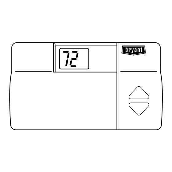
Bryant's 7-day programmable Thermidistat Control is a wall-
mounted, low-voltage control which combines temperature and
humidity control in a single attractive unit. An extension of
Bryant's proven line of thermostats, it provides separate set points
for heating and cooling, and now adds humidification and dehu-
midification. Different heating and cooling set points and times are
programmable for 4 periods per day and 7 days per week. The
Thermidistat Control can also be field-configured as a non-
programmable
thermostat.
programmable configuration it will still have both temperature and
humidity control. Humidify and dehumidify outputs provide direct
control of humidity. Batteries are not used. During power loss an
internal memory stores programs and settings for unlimited time,
and the clock continues to run for at least 8 hr.
installation and
start-up instructions
THERMIDISTAT™ CONTROL
When
operating
in
the
A. Power
Note that this control does not require batteries and is not "power
stealing." It does require 24vac (R and C terminals) of the
low-voltage transformer to be connected to it for proper operation.
Page
It will not operate without these 2 connections.
B. Models
There is a single programmable/non-programmable model for all
applications. It can be configured for AC or HP, 1- or 2-speed
compressor, and for dual fuel installations, allowing it to be used
in place of all Bryant thermostats.
C. Humidify Equipment and Connections
The humidify output connects directly to 24vac operated humidi-
fiers. No other connection or interlock is required. Any of several
installer-selectable operating modes are available.
D. Dehumidify Equipment and Connections
The dehumidify output connects to the dehumidify input on
variable-speed furnaces and fan coils. Additional dehumidification
is done by controlling the compressor. A variety of operating
modes are available.
E. Outdoor Temperature Sensor
→
Optimum performance is obtained when an outdoor temperature
sensor is used with the Thermidistat Control. Plan installation so
that 2 wires can be run from Thermidistat Control to an outdoor
location, preferably on the north side of the house or refer to
Installation Instructions included with the outdoor temperature
sensor for simplified connection. Sensor can be mounted to
.
outdoor unit and existing control wires may be used for its
connection. Details are provided in sensor instructions.
HEIGHT (IN.)
4-1/4
non-
I. THERMIDISTAT CONTROL LOCATION
Thermidistat Control should be mounted:
• Approximately 5 ft (1.5m) from floor.
• Close to or in a frequently used room, preferably on an inside
partitioning wall.
-1-
Cancels: II TSTAT-0-16
INSTALLATION CONSIDERATIONS
WIDTH (IN.)
7-1/2
Fig. 1-Thermidistat Control
INSTALLATION
TSTAT
II TSTAT-0-20
5-98
®
A96373
DEPTH (IN.)
1-3/8
Advertisement
Table of Contents

Related Manuals for Bryant II TSTAT-0-16


Summary of Contents for Bryant II TSTAT-0-16
-
Page 1: Table Of Contents
A96373 humidity control in a single attractive unit. An extension of HEIGHT (IN.) WIDTH (IN.) DEPTH (IN.) Bryant’s proven line of thermostats, it provides separate set points 4-1/4 7-1/2 1-3/8 for heating and cooling, and now adds humidification and dehu- midification. -
Page 2: Set Dip Switches
III. INSTALL THERMIDISTAT CONTROL • On a section of wall without pipes or duct work. Thermidistat Control should NOT be mounted: WARNING: Before installing Thermidistat Control, • Close to a window, on an outside wall, or next to a door leading turn off all power to equipment. -
Page 3: Set Thermidistat Control Configuration
5. dF—for 1-speed dual fuel D. Configuration Options — Selection: 6. d2—for 2-speed dual fuel OPTION 1—ANTICIPATOR ADJUSTMENT This adjustment controls sensitivity and cycle rate of Thermidistat 7. HS—for special 3-stage auxiliary heat with FK series Fan Control. Higher numbers decrease sensitivity and slow cycle rate. Coil and 1-speed heat pump Lower numbers increase sensitivity and cycle rate. - Page 4 OPTION 4—FAN (G) ON WITH W 1. Enter configuration mode if not already there. See Step 4 "To Enter Configuration Mode." Use up and down buttons This selection determines whether fan (G) output is to be ON or to make small (now flashing) display indicate 07. OFF when any W (furnace or strip heat) output is ON.
- Page 5 High Pressure Switch Kit includes required switch and instructions TABLE 1—W1 / W2 OUTPUTS for proper operation. For all dual fuel installations, outdoor SELECTION DEFINITION temperature sensor must be attached. If not, E3 error message will Neither W1 or W2 is turned on. appear.
-
Page 6: System Start-Up And Checkout
OPTION 14—HEAT/COOL DEAD BAND ADJUSTMENT Both programmable and non-programmable versions of the Ho- meowner’s Manual are available. This option selects the minimum difference between heat and cool set points. A larger difference saves energy and a smaller differ- Once it has been determined that a particular installation is to be ence decreases temperature difference between heating and cool- made non-programmable, the only changes required are: ing. -
Page 7: Final Settings
COPY PREVIOUS DAY PROGRAM MODE SET COOL SET DHUM MODE CHANGE DAY HUMIDITY SET HEAT SET HUM SET TIME/TEMP VACATION HOLD/END SET TIME VACATION Reset Reset Filter Filter PROGRAMMABLE CONFIGURATION NON-PROGRAMMABLE CONFIGURATION (OPTION 17 OFF) (OPTION 17 ON) A98286 → Fig. 2—Programmable/Non-Programmable Keypad Labels B. -
Page 8: Dehumidification
TABLE 2—EQUIPMENT OUTPUTS 1-SPEED AC 2-SPEED AC 1-SPEED HP 2-SPEED HP Cool—0 to 2 minutes Y, G Y1, G Y, G, O Y1, G, O Cool—2 to 4 minutes Y, G Y1, Y2, G Y, G, O Y1, Y2, G, O Heat—0 to 2 minutes Y, G Y1, G... -
Page 9: Vacation
COOL TO, AND OFF) ment. → Bryant FK Series Variable-Speed Fan Coils, all 333BAV and Press HUMIDITY button to bring up humidity selections. Succes- 333JAV 80% Variable-Speed Furnaces, and 355MAV 90% sive presses will show "hu" or "dhu" in clock display. Select "dhu"... -
Page 10: Operational Information
→ TABLE 6—WIRING DIAGRAM REFERENCE CHART SINGLE-SPEED TWO-SPEED SINGLE-SPEED TWO-SPEED EQUIPMENT SELECTION AIR CONDITIONER AIR CONDITIONER HEAT PUMP HEAT PUMP Typical Fan Coil Fig. 3 Fig. 4 Fig. 5 Fig. 6 FK4C Fan Coil Fig. 7 Fig. 8 Fig. 9 Fig. -
Page 11: Wiring Diagrams
TYPICAL 2-SPEED TYPICAL 1-SPEED THERMIDISTAT FAN COIL AIR CONDITIONER FAN COIL THERMIDISTAT AIR CONDITIONER Y1/W2 COOL STAGE 1 HEAT STAGE 2 O/W2 HEAT STAGE 2 O/W2 Y1/W2 W/W1 HEAT STAGE 1 HEAT STAGE 1 W/W1 Y/Y2 COOL STAGE 2 Y/Y2 COOL STAGE 1 24 VAC HOT 24 VAC HOT... - Page 12 FK SERIES 1-SPEED THERMIDISTAT FAN COIL AIR CONDITIONER FK SERIES 2-SPEED THERMIDISTAT FAN COIL AIR CONDITIONER HEAT STAGE 2 O/W2 HEAT STAGE 2 O/W2 REMOVE J2 JUMPER Y1/W2 FOR HEAT STAGING REMOVE J2 JUMPER FOR HEAT STAGING HEAT STAGE 1 W/W1 W/W1 HEAT STAGE 1...
- Page 13 1-STAGE 2-SPEED 1-STAGE 1-SPEED FURNACE THERMIDISTAT AIR CONDITIONER THERMIDISTAT FURNACE AIR CONDITIONER O/W2 O/W2 Y1/W2 COOL STAGE 1 Y1/W2 W/W1 HEAT STAGE 1 HEAT STAGE 1 W/W1 COOL STAGE 2 Y/Y2 Y/Y2 COOL STAGE 1 24 VAC HOT 24 VAC HOT 24 VAC COMM DHUM DHUM...
- Page 14 2-STAGE 1-SPEED 2-STAGE 2-SPEED FURNACE THERMIDISTAT AIR CONDITIONER THERMIDISTAT FURNACE AIR CONDITIONER HEAT STAGE 2 O/ W2 O/W2 HEAT STAGE 2 Y1/W2 Y1/W2 COOL STAGE 1 HEAT STAGE 1 W/W1 W/W1 HEAT STAGE 1 W/ W1 W/W1 Y/Y2 COOL STAGE 1 Y/Y2 Y/Y2 Y/Y2...
- Page 15 VARIABLE SPEED 80% NON-CONDENSING FURNACE VARIABLE SPEED 80% NON-CONDENSING FURNACE BOARD BOARD 1-SPEED FURNACE THERMIDISTAT AIR CONDITIONER THERMIDISTAT BOARD 2-SPEED AIR CONDITIONER FURNACE O/W2 HEAT STAGE 2 COOL STAGE 1 Y1/W2 BOARD Y1/W2 O/W2 HEAT STAGE 2 HEAT STAGE 1 W/ W1 W/W1 HEAT STAGE 1...
- Page 16 VARIABLE-SPEED CONDENSING 2-SPEED VARIABLE-SPEED THERMIDISTAT FURNACE AIR CONDITIONER 1-SPEED CONDENSING THERMIDISTAT AIR CONDITIONER FURNACE O/W2 HEAT STAGE 2 O/W2 HEAT STAGE 2 Y1/W2 COOL STAGE 1 Y1/W2 W/W1 HEAT STAGE 1 W/W1 HEAT STAGE 1 W/ W1 W/W1 Y/Y2 Y/Y2 COOL STAGE 2 Y/Y2 Y/Y2...
- Page 17 VARIABLE-SPEED VARIABLE-SPEED CONDENSING CONDENSING 2-SPEED FURNACE FURNACE AIR CONDITIONER THERMIDISTAT THERMIDISTAT HEAT STAGE 2 O/W2 HEAT STAGE 2 O/W2 1-SPEED AIR CONDITIONER Y1/W2 COOL STAGE 1 Y1/W2 W/W1 W/W1 HEAT STAGE 1 W/W1 HEAT STAGE 1 W/W1 COOL STAGE 1 Y/Y2 Y/Y2 Y/Y2...
- Page 18 9. Outdoor air sensor must be attached in all dual fuel applications. 10. Refer to indoor equipment Installation Instructions for proper setup. 11. →To activate dehumidify feature on older style variable-speed furnaces (Bryant 335MAV) that do not have a DE connection, a pilot duty 24-vac relay must be used.
-
Page 19: Thermidistat Control Troubleshooting
K. Power On Check E4 — If Thermidistat Control’s internal memory fails, E4 will be displayed. Replace Thermidistat Control. When AC power is first applied, all segments of display are turned E5 — If Thermidistat Control cannot properly read humidity, E5 on for a few seconds. - Page 20 Course descriptions and schedules are in our catalog. CALL FOR FREE CATALOG 1-800-962-9212 [ ] Packaged Service Training [ ] Classroom Service Training A94328 © 1998 Bryant Heating & Cooling Systems 7310 W. Morris St. Indianapolis, IN 46231 —20— Printed in U.S.A. itstt020 Catalog No. 13TS-TA6...
Need help?
Do you have a question about the II TSTAT-0-16 and is the answer not in the manual?
Questions and answers