Advertisement
Installation Instructions
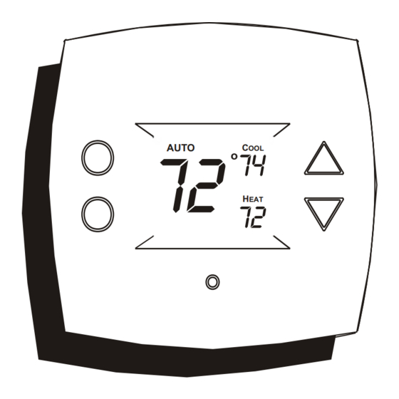
TSTATCCPB101
TSTATBBPB101
P474-1010
NOTE: Read the entire instruciton manual before starting the installation.
72
AUTO
MULTI-STAGE
Form: IM-TSTAT-07
HEAT
COOL
74
C
OOL
72
H
EAT
HEAT
PUMP
SINGLE DAY PROGRAMMABLE
Cancels:
Printed in U.S.A.
Digital Thermostat
&
Catalog No. 13TS-TA43
Advertisement
Table of Contents

Related Manuals for Bryant TSTATCCPB101


Summary of Contents for Bryant TSTATCCPB101
-
Page 1: Installation Instructions
Installation Instructions TSTATCCPB101 Digital Thermostat TSTATBBPB101 P474-1010 NOTE: Read the entire instruciton manual before starting the installation. HEAT COOL AUTO & HEAT PUMP MULTI-STAGE SINGLE DAY PROGRAMMABLE Form: IM-TSTAT-07 Cancels: Printed in U.S.A. Catalog No. 13TS-TA43... -
Page 2: Table Of Contents
Table Of Contents PREPARATION REMOVE OLD THERMOSTAT INSTALL BACKPLATE & WIRE WIRING DIAGRAMS CALIBRATION TEST OPERATION TROUBLESHOOTING CAUTION Follow Installation Instructions carefully. DISCONNECT POWER TO THE HEATER - AIR CONDITIONER BEFORE REMOVING THE OLD THERMOSTAT AND INSTALLING WARNING THE NEW THERMOSTAT. Replacement Components Division Carrier Corporation 4/01 This device complies with Part 15 of the FCC rules. -
Page 3: Preparation
STEP #1 PREPARATION Proper installation of the thermostat will be accomplished by following these step by step instructions. If you are unsure about any of these steps, call a qualified technician for assistance. Assemble tools as shown below. Drill with 3/16 inch Drill Bit Flat Blade (when not using... -
Page 4: Remove Old Thermostat
STEP #2 REMOVE OLD THERMOSTAT Turn off the power to the Heating/Air Conditioning system at the main fuse panel. Most residential systems have a separate breaker for disconnecting power to the furnace. Remove the cover of the old thermostat. If it does not come off easily check for screws. -
Page 5: Install Backplate & Wire
STEP #3 INSTALL BACKPLATE & WIRE Remove the backplate connector from the rear of the thermostat. Install wires as directed below. When finished, snap thermostat on to backplate. If the terminal designations on your old thermostat do not match those on the new thermostat, refer to the chart below, or the wiring diagrams that follow. -
Page 6: Wiring Diagrams
Sample Wiring Diagrams 5 Wire, 1 Stage Cooling, 1 Stage Gas Heat Residential Gas or Electric Heat *, Electric Cool, split systems & package units Thermostat 24 vac common fan relay compressor relay 1st stage heat circuit 24 vac return * If using electric heat this option must be selected on during advanced setup. -
Page 7: Sample Wiring Diagrams
Sample Wiring Diagrams 6 Wire, 2 Stage Cooling, 1 Stage Heat Residential 2 Stage Cooling, with Gas or Electric Heat* Thermostat 24 vac common fan relay compressor relay 1st stage heat circuit 24 vac return 2nd stage compressor relay * If using electric heat, this option must be selected during advanced setup. - Page 8 Sample Wiring Diagrams Commercial Gas or Electric Heat ***, 7 Wire, 2 Stage Cooling, 2 Stage Heat Electric Cool, split systems & package units including Commercial Heat Pumps ** Thermostat 24 vac common fan relay compressor relay 1st stage heat circuit 24 vac return 2nd stage compressor relay 2nd stage heat circuit...
-
Page 9: Calibration
Sample Wiring Diagram 6 Wire, 1 Stage Cooling, 2 Stage Heat, Heat Pump * Most residential split and package heat pumps with auxiliary heat Thermostat 24 vac common fan relay compressor relay 1st stage heat circuit 24 vac return 2nd stage heat circuit * The heat pump option must be selected on during advanced setup. -
Page 10: Test Operation
STEP #4 TEST OPERATION Turn the power on to the Heating/Air Conditioning system. Press the MODE button repeatedly until the HEAT icon appears on the display. Press the up/down buttons until the set temperature is 10 degrees above room temperature. The furnace should turn on. Press the MODE button repeatedly until the COOL icon appears on the display. -
Page 11: Troubleshooting
TROUBLESHOOTING SYMPTOM: When using 4 wires (R, G, W, Y), the air conditioning or heat equipment tries repeatedly to turn on, but cannot. At times the display dims or disappears. CAUSE: There is not enough power available to "power share". REMEDY: Connect a 270 ohm, 10 watt power resistor at the furnace as shown below. - Page 12 TROUBLESHOOTING SYMPTOM: The air conditioning does not attempt to turn on. CAUSE: The cooling setpoint is set too high. REMEDY: Consult the Owner's Manual in the Setup section to lower the cooling setpoint limit. SYMPTOM: The heating does not attempt to turn on.
- Page 13 "conventional" (non heat pump) system. REMEDY: Consult the Owner's Manual in the Advanced Setup section to turn off the heat pump. STAR TSTATCCPB101 TSTATBBPB101 P474-1010 Tested to Comply with FCC Standards FOR HOME OR OFFICE USE 4Z95...
Need help?
Do you have a question about the TSTATCCPB101 and is the answer not in the manual?
Questions and answers