Table of Contents
Advertisement
Heating & Cooling Systems
SINGLE STAGE HEAT & COOL
THERMOSTAT
72
Heat Cool Thermostat
USERS INFORMATION MANUAL
M O D E L T S T A T B B N Q 0 0 1
N O N - P R O G R A M M A B L E D I G I T A L
T H E R M O S T A T
NOTE TO INSTALLER:
This manual must be left with the equipment user.
Battery Operated
4-Wire Operation
Millivolt Compatible
Digital Display
DC Voltage Compatible
Stage: 1-Heat, 1-Cool
Easy Slide Switch
Operation
Advertisement
Table of Contents

Related Manuals for Bryant TSTATBBNQ001


Summary of Contents for Bryant TSTATBBNQ001
- Page 1 Heating & Cooling Systems SINGLE STAGE HEAT & COOL THERMOSTAT Heat Cool Thermostat USERS INFORMATION MANUAL M O D E L T S T A T B B N Q 0 0 1 N O N - P R O G R A M M A B L E D I G I T A L...
-
Page 2: Table Of Contents
Table Of Contents LOCATION OF CONTROLS DISPLAY NORMAL OPERATION PREPARATION REMOVE OLD THERMOSTAT INSTALLATION AND BATTERY REPLACEMENT WIRE CONNECTIONS JUMPER CONFIGURATION TEST OPERATION TROUBLESHOOTING WARRANTY Bryant Heating & Cooling Systems Patents Pending 4/03 Page 1... -
Page 3: Safety Warnings
The annual battery replacement is especially critical in locations subject to freezing temperatures. The thermostat will be unable to turn on the Heat if the batteries are exhausted. This device complies with Part 15 of the FCC rules. -
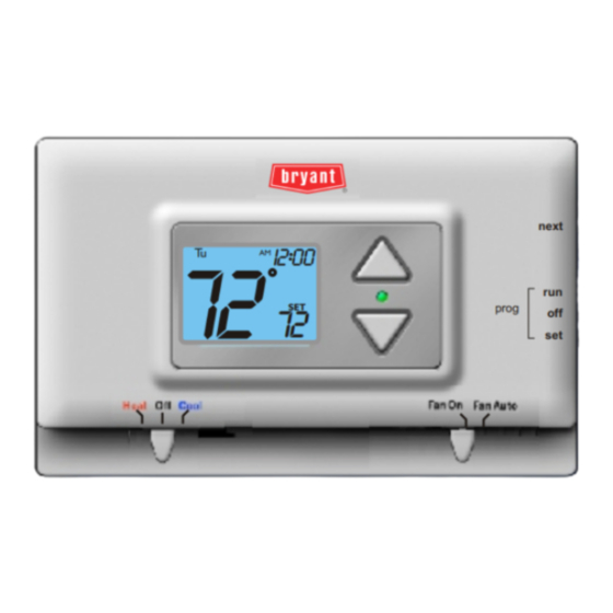
Page 4: Location Of Controls
Location of Controls MODE SWITCH Heat, Cool or Off UP & DOWN BUTTONS FAN SWITCH On or Auto Page 3... -
Page 5: Display
Current room temperature. If the Up or Down arrow buttons are pressed the thermostat will show the desired Set Temp temperature indicator. Once this screen is reached you may use the Up or Down arrow buttons to adjust the desired room temperature. -
Page 6: Normal Operation
Normal Operation MODE SWITCH Heat, Cool or Off Manual Operation Select heat or cool with the mode switch. Normally leave the fan switched to auto. In fan auto, the fan will turn on only with a heat or cool demand. When Fan On is selected, the fan will run continuously, even when the mode switch is set to Off. -
Page 7: Preparation
Step #1 Proper installation of the thermostat will be accomplished by following these step Heat Off Cool Fan On FanA uto by step instructions. If you are unsure about any of these steps, call a qualified technician for assistance. These tools will be required:... -
Page 8: Remove Old Thermostat
Step #2 Remove the cover of the old thermostat. If it does not come off easily check for Heat Off Cool Fan On FanA uto screws. Loosen the screws holding the thermostat base or subbase to the wall, and lift away. -
Page 9: Installation And Battery Replacement
Step #3 To Open The Thermostat The top of the thermostat housing has two (2) screw- driver slots to assist when seperating. To pull the housing apart, insert a small blade screw- driver into the slot and rotate 90 . This will release the top housing snaps. - Page 10 Battery Replacement REPLACE WITH ALKALINE BATTERIES AT LEAST ONCE EVERY YEAR, OR WHEN THE “LOW BATTERY” APPEARS (pages 2,8). POSITION BATTERIES AS SHOWN USE “AA” SIZE ALKALINE BATTERIES USE “AA” SIZE ALKALINE BATTERIES FAN W/ HEAT HEAT PUMP Page 9 ICON...
-
Page 11: Wire Connections
Wire Connections Install on the new thermostat Function connector marked Heating Cooling Rev. Valve (Energize to Heat) Rev. Valve (Energize to Cool) Power 4Z95 ALKALINE BATTERIES Wire Slots Page 10 MODEL: TSTATBBNQ001 97061606 USE SIZE “AA” MADE IN CHINA Fig. 1... -
Page 12: Sample Wiring Diagrams
4 Wire, 1 Stage Cooling, 1 Stage Gas Heat POWER COOLING GAS OR ELECTRIC HEAT Residential Gas or Electric Heat *, Electric Cool, split systems & package units 4 Conductor 18 to 22 gauge unshielded cable from the thermostat to the equipment. Page 11... - Page 13 Residential Heat Pumps, split systems & package units, with no auxiliary heat. POWER REVERSING VALVE COMPRESSOR For Heat Pump or Electric Heat applications see page 17 or 18 for Jumper configuration. 4 Conductor 18 to 22 gauge unshielded cable from the thermostat to the equipment. Page 12...
- Page 14 Residential Heat Pumps, split systems & package units, with no auxiliary heat. POWER REVERSING VALVE COMPRESSOR For Heat Pump or Electric Heat applications see page 17 or 18 for Jumper configuration. 4 Conductor 18 to 22 gauge unshielded cable from the thermostat to the equipment. Page 13...
- Page 15 Sample Wiring Diagrams 3 Wire, 1 Stage Heat POWER GAS OR ELECTRIC HEAT Residential Gas or Electric Heat units with a separately controlled fan. 3 Conductor 18 to 22 gauge unshielded cable from the thermostat to the equipment. Page 14...
- Page 16 Sample Wiring Diagrams 2 Wire, 1 Stage Gas Heat POWER GAS OR ELECTRIC HEAT Residential Gas or Millivolt units. 2 Conductor 18 to 22 gauge unshielded cable from the thermostat to the equipment. Page 15...
- Page 17 Sample Wiring Diagrams 3 Wire, 1 Stage Cooling POWER COOLING Residential Electric Cool units 3 Conductor 18 to 22 gauge unshielded cable from the thermostat to the equipment. Page 16...
-
Page 18: Jumper Configuration
Step #5 Figure-A) Jumper factory default positions for typical gas Heat Off Cool Fan On FanA uto furnace heating with electric cooling. Cooling Mode Heating Mode *Outputs active - For normal operation do not connect to equipment Jumper Configuration FAN W/ HEAT HEAT PUMP and Jumper are shown in the... - Page 19 Step #5 Figure-B) Jumper with Heat (W). Jumper Heat Off Cool Fan On FanA uto factory default position. Cooling Mode Heating Mode *Outputs active - For normal operation do not connect to equipment Jumper Configuration FAN W/ HEAT HEAT PUMP is used to select Fan On (G) shown in the OUTPUTS...
-
Page 20: Heat Pump Applications
Step #5 Figure-C) Jumper heat pump operation. Note: Thermostat Heat Off Cool Fan On FanA uto Does Not Have Auxiliary Heat / Emergency Heat Capability. Leave jumpers in original factory default positions (figure-A) for non heat pump applications. Cooling Mode... -
Page 21: Test Operation
Conditioning system. Heat Off Cool Fan On FanA uto Adjust the Slide Switch until it is located under the word HEAT on the thermostat. Heat Off Cool Fan On FanA uto Press the Up or Down buttons until the set temperature is 10 degrees above room temperature. -
Page 22: Troubleshooting
Troubleshooting SYMPTOM: The slide switches on the thermostat are very difficult to move. Heat Off Cool Fan On FanA uto CAUSE: The backplate of the thermostat is deformed by being screwed tightly into a wall that is not perfectly flat. - Page 23 REMEDY: Consult the Normal Operation section in this manuals to raise the heating setpoint and to correct the Mode Switch position, or replace the batteries (Page 9). 4Z95 Battery Stat TSTATBBNQ001 Tested to Comply with FCC Standards FOR HOME OR OFFICE USE Page 22...
-
Page 24: Warranty
Warranty 5-Year Warranty - This Product is warranted to be free from defects in material and workmanship. If it appears within five years from the date of original installation, whether or not actual use begins on that date, that the product does meet this warranty, a new or remanufactured part, at the manufacturer’s sole option, to replace any defective part will be provided without charge for the part itself;...
Need help?
Do you have a question about the TSTATBBNQ001 and is the answer not in the manual?
Questions and answers