Table of Contents
Advertisement
Owners Manual
Including Installation Instructions and Warranty Information
HEAT PUMP WATER, POOL & FLOOR HEATERS
Document Number : QDC0049PD-5
WATER & POOL HEATERS
OWNER'S MANUAL
To Suit 67AC
67ACW2-134
67ACW2-134-C
67ACW-134
67ACW-134-C
67ACW-417
67ACW-417B
67ACP2-22
67ACP-407
67ACP-407-C
67ACP2-407
67ACB-407B
67ACB-417B
Document Number: QDC0049PD-5
Date of Revision: July 2009
Quantum Energy Technologies
MODELS
Page 1 of 33
Advertisement
Table of Contents
Troubleshooting

Summary of Contents for Quantum 67ACW2-134
- Page 1 Quantum Energy Technologies Owners Manual WATER & POOL HEATERS OWNER’S MANUAL Including Installation Instructions and Warranty Information To Suit 67AC HEAT PUMP WATER, POOL & FLOOR HEATERS MODELS 67ACW2-134 67ACW2-134-C 67ACW-134 67ACW-134-C 67ACW-417 67ACW-417B 67ACP2-22 67ACP-407 67ACP-407-C 67ACP2-407 67ACB-407B 67ACB-417B...
-
Page 2: Table Of Contents
Quantum Energy Technologies Owners Manual Contents Section 1: APPLIANCE DETAILS ……………………………………………………..…..….….5 1a: Owner’s Details........................5 1b: Installer’s Details ........................5 1c: Service History........................5 Section 2: INTRODUCTION ………………………………………………………………………6 2a: Model Code..........................6 2b: General Description ........................ 7 2c: Inspection on Delivery ......................7 2d: Physical Data .......................... - Page 3 Quantum Energy Technologies Owners Manual 3g: Building Heating........................14 3g.1: System Volume ........................14 3g.2: Schematic of the heating system..................15 3h: Field Wiring .......................... 16 3h.1: Wire Sizing........................16 3h.2: Electrical Data Table ....................16 3h.3: Wiring Diagram......................17 Section 4: CONTROL LAYOUT AND OPERATION ……………………………………...…...19...
- Page 4 Quantum Energy Technologies Owners Manual 6c: Refrigerant Sight Glass ......................25 6d: Evaporator Fan........................26 6e: Electrical Terminals ......................26 6f: Evaporator Coils ........................26 6g: Operating Parameters......................26 6h: Service Warnings ........................27 6i: Thermostatic Expansion Valve....................27 6j: Filter Drier ..........................27 6k: Liquid Line Solenoid ......................
-
Page 5: Section 1: Appliance Details
Quantum Energy Technologies Owners Manual Section 1: APPLIANCE DETAILS For future convenience, please fill in the following details and retain with your original invoice. 1a: Owner’s Details Surname : …………………………………… Given Name(s) : ….………………………..Address : ……………………………………………………………………………...………… Town/Suburb : ……………………………………………………………………..……………... -
Page 6: Acw2
It has a cold side to absorb heat at low temperatures and a hot side to deliver heat at high temperatures. The Quantum system has an air coil as the cold side of the refrigeration circuit. This coil absorbs the heat from air that is forced through it by means of the fan. -
Page 7: 2B: General Description
Check the unit nameplate to be sure it agrees with the power supply available. Units are shipped FOB factory and Quantum is not responsible for physical damage after the unit leaves the factory. For unit shipping weights see section 2d.1: Physical Data Table. -
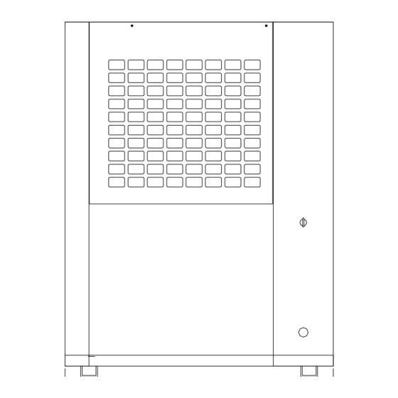
Page 8: 2D.2: Dimensions
Quantum Energy Technologies Owners Manual 2d.2: Dimensions 1121 Mo del No67ACW2-134-C Serial No SUZ0027 Date of MfgDec 2006 Hot Water Generating Rate542 l/h Heat ing C ap acit y22.10 kW Po wer In put (to tal)7.36 kW Typical Operatin g Amps15 Amps... -
Page 9: Section 3: Installation
Quantum Energy Technologies Owners Manual Section 3: INSTALLATION Trained, experienced personnel, who are familiar with local codes and regulations, especially concerning refrigerant release to the atmosphere, must perform installation. WARNING Sharp edges and coil surfaces can cause personal injury. Avoid contact with them. -
Page 10: 3B: Location
Quantum Energy Technologies Owners Manual Figure 3: Clearance Requirements 3b: Location 3b.1: Unit Placement 1000mm Clearance for Units are for outdoor applications and can be Air Inlet mounted on a roof or at ground level. 1200mm 1200mm The location shall be dry and not subject... -
Page 11: 3B.3: Clearances
3b.4: Sound Isolation The sound level of the Quantum water heater is suitable for most applications. When additional sound reduction is necessary, locate the unit away from sound sensitive areas. Avoid locations beneath windows or between structures where normal operating sounds may be objectionable. -
Page 12: 3C: Refrigerant Charge
Quantum Energy Technologies Owners Manual 3c: Refrigerant Charge All units are shipped with an operating refrigerant charge. The operating charge for each unit is shown in section 2d.1 Physical Data Table. 3d: Water System 3d.1: Water Piping Local authorities can advise the installer on the current building and safety codes required for proper installation. -
Page 13: 3D.2: Flow Switch
Quantum Energy Technologies Owners Manual 3d.2: Flow Switch A flow switch is already installed on the water inlet line to shut down the unit if water flow is interrupted. The minimum flow rate required to close the switch is about 40LPM. -
Page 14: 3G: Building Heating
Quantum Energy Technologies Owners Manual Figure 5: Hydraulic Connections To Pool Heater Showing shut-off by-pass valves (Optionally fitted by plumber to isolate the heater) Heated Water To Pool Optional Quantum Heater Unit Shut-off By Pass Cold Water From Pool All Pipes Are 40 mm PVC... -
Page 15: 3G.2: Schematic Of The Heating System
Quantum Energy Technologies Owners Manual total amount of water in the condenser, air handling components (such as radiator panels or fan heater units) and associated piping. If the water volume is too low operational problems can occur including rapid compressor cycling, erratic refrigerant flow in the water heater, improper motor cooling, shortened equipment life and other undesirable symptoms. -
Page 16: 3H: Field Wiring
Quantum Energy Technologies Owners Manual 3h: Field Wiring 3h.1: Wire Sizing Wiring must comply with all applicable codes and ordinances. Warranty is void if wiring is not in accordance with specifications. Copper wire is required for all power lead terminations at the unit. -
Page 17: 3H.3: Wiring Diagram
Quantum Energy Technologies Owners Manual 3h.3: Wiring Diagram Figure 7a: Typical Field Wiring Diagram for Axial Fan Models F A N C O M P 5 0 H Z / T N - S 3 8 0 / 2 2 0 V... -
Page 18: Figure 7B: Typical Field Wiring Diagram For Centrifugal Fan
Quantum Energy Technologies Owners Manual Figure 7b: Typical Field Wiring Diagram for Centrifugal Fan Models F A N C O M P 5 0 H Z / T N - S 3 8 0 / 2 2 0 V Q F 1... -
Page 19: Section 4: Control Layout And Operation
Quantum Energy Technologies Owners Manual Section 4: CONTROL LAYOUT AND OPERATION 4a: Control Centre The electrical controls are installed in three locations: the left panel (on/off switch), the front panel (the digital display) and the enclosure in side the unit cabinet. (Normally the left-hand section contains the microprocessor controller as well as the control input and output terminals. -
Page 20: 4B.2. The Buttons
Quantum Energy Technologies Owners Manual 4b.2: The Buttons Use in conjunction with the Layout Diagram Fig 6 and Wiring Diagrams Fig 7&8. 4b.3: SET Button a) To enter the settings node, press the SET button 3 times; the display will show H60 (or H26) for water heaters (or pool heaters), this is the water temperature cut out set point. -
Page 21: 4B.8: Operating Principle
Quantum Energy Technologies Owners Manual 4b.8: Operating Principle At power on the compressor will start after the 10 min time delay (1 Level t10). When the water temperature reaches 60°C the compressor will be de-activated. As the water temperature drops... -
Page 22: Section 5: Operation
On all Quantum units the sensors are factory mounted. Check that the voltage of the power supply to the unit is within ±10% of the nameplate rating. -
Page 23: 5C: Sequence Of Operation
Quantum Energy Technologies Owners Manual The superheat is calculated as the difference between the temperature of the suction refrigerant and the saturated temperature corresponding to the suction pressure, as illustrated below: Suction temperature (measured) t: _____________ °C Suction Pressure (measured): _____________ kPa Saturated temperature (property table) t : _____________ °C... -
Page 24: 5D: Thermal Overload
Should the compressor continue to “trip” the thermal overload, turn off the machine, de-energise and isolate the power supply at the POINT OF SUPPLY. Please contact Quantum or its duly appointed and authorised representative, who will arrange for a service technician to check and/or repair the machine. -
Page 25: Section 6: Maintenance
On initial start-up and periodically during operation, it will be necessary to perform certain routine service checks. WARNING If a system failure occurs due to improper maintenance during the warranty period, Quantum will not be liable for costs incurred to return the system to satisfactory operation. 6b: Compressor 6b.1: Lubrication Oil... -
Page 26: 6D: Evaporator Fan
Quantum Energy Technologies Owners Manual Figure 11: Sight Glass Moisture Indicator SIGHT GLASS (“green” colour in centre indicating dry refrigerant) 6d: Evaporator Fan No routine lubrication is required of the fan motor. The fan motor bearings are of the permanently lubricated type and require no lubrication. -
Page 27: 6H: Service Warnings
Quantum Energy Technologies Owners Manual 6h: Service Warnings WARNING Disconnect and tag out all power sources to the unit before doing any service inside. Failure to do so can cause severe personal injury or death. CAUTION Service on this equipment is to be performed by qualified service personnel with particular regard to regulations concerning release of refrigerant to atmosphere. -
Page 28: 6L: Optional Controls
Quantum Energy Technologies Owners Manual 6l: Optional Controls 6l.1: Hot Gas Bypass (for 67ACW- 417, 67ACP2-xxx, 67ACB-xxx) Hot gas bypass is a system for maintaining evaporator pressure at or above a minimum value. The purpose for doing this is to keep the velocity of the refrigerant, as it passes through the evaporator, high enough for proper oil return to the compressor when the ambient temperature is very low. -
Page 29: 6M.1: Trouble Shooting Chart
Quantum Energy Technologies Owners Manual 6m.1: Trouble Shooting Chart POSSIBLE CAUSES POSSIBLE CORRECTIVE STEPS PROBLEM 1. Main switch open Close switch 2. Fuse blown, breakers open Check electrical circuits and motor windings for shorts. Check for overloads and loose connections. Replace fuse or reset breaker. -
Page 30: Section 7: Warranty Details For 67Ac Heater Units
The date and time of the commencement of such warranty work will be at the discretion of the Company. Quantum does not warrant that such repair work will take place within any particular period. A call out fee applies to any warranty calls made outside normal QUANTUM business hours. -
Page 31: 7B: Items Not Covered By Warranty
Quantum Energy Technologies Owners Manual 7b: Items Not Covered By Warranty Service calls due to: • Dirty Filters. • Blown Fuses • Incorrect Operation. • Tripped Circuit Breakers. • Main Isolator Switched Off. • Blocked Drains (such as from the Evaporator etc). - Page 32 Quantum Energy Technologies Owners Manual Customer Notes: Page 32 of 33 Document Number : QDC0049PD-5...
- Page 33 QUANTUM ENERGY TECHNOLOGIES PTY LTD 56-60 Bourke Road Alexandria NSW 2015 AUSTRALIA. A.B.N: 88 095 959 327 Phone: (+61 2) 9699 7444 Fax (61 2) 9699 5386 NOTE: While every care has been taken to ensure the accuracy in preparing this publication, No liability can be accepted for any consequences, which may arise as a result of its application.
Need help?
Do you have a question about the 67ACW2-134 and is the answer not in the manual?
Questions and answers