Table of Contents
Advertisement
Quick Links
Advertisement
Table of Contents

Related Manuals for Orion WB-71


Summary of Contents for Orion WB-71
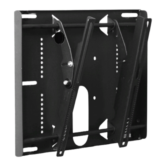
- Page 1 Installation and User’s Guide Installation and User’s Guide BIG SCREEN FLAT LCD DISPLAY MOUNT MODEL WB-71 WALL MOUNT BRACKET http://www.orionimages.com All contents of this document may change without prior notice, and actual product appearance may differ from that depicted herein...
-
Page 2: Table Of Contents
Parts List ..........................Installation Tools ........................Mounting Bracket Installation ....................WB-71 Installation ........................ 12 Installing the Flat Panel Display (WB-71) ................Technical Specifications ...................... Warranty ..........................Contact ..........................7300 Bolsa Avenue, Westminster CA 92683 / Tel: 714-766-6300 / Fax: 714-766-6310... -
Page 3: Warning Statements
Recommended mounting surfaces: wooden studs and solid-flat concrete. If the mount is to be installed on any surface other than wooden studs, use suitable hardware (which is commercially available). Contact Orion Images with any technical/ installation questions. 7300 Bolsa Avenue, Westminster CA 92683 / Tel: 714-766-6300 / Fax: 714-766-6310... -
Page 4: Part List
This wall mount is shipped with all proper installation hardware and components. Make sure that none of these parts are missing and/or damaged before beginning installation. If there are parts missing and/or damaged, please stop the installation and contact Orion Images. 714-766-6300 Mounting... - Page 5 Installation and User’s Guide http://www.orionimages.com 7300 Bolsa Avenue, Westminster CA 92683 / Tel: 714-766-6300 / Fax: 714-766-6310...
- Page 6 Installation and User’s Guide http://www.orionimages.com Nylon spacers and flat washers actual size NOTE The nylon spacers may be stacked to achieve proper spacing. 1/2" Nylon spacers (Qty 6) (large) 5/16" Flat washers (metal) (Qty 6) 1/4" Nylon spacers (Qty 6) 7300 Bolsa Avenue, Westminster CA 92683 / Tel: 714-766-6300 / Fax: 714-766-6310...
- Page 7 Installation and User’s Guide http://www.orionimages.com Thread Depth Indicator Insert the thread depth indicator (supplied) through the thread inserts found on the back of the flat panel to make sure the inserts measure the same full depth and mark it (Figure 1). Locate the correct diameter screw for the thread insert.
-
Page 8: Mounting Bracket Installation
Installation and User’s Guide http://www.orionimages.com Mounting Bracket Installation NOTE: Proper installation procedure by qualified personnel as outlined in the installation instructions must be adhered to. Failure to do so could result in serious personal injury and possible damage to the flat panel. WARNING: INVERT THE FLAT PANEL PLACE IT ON A SOFT, FLAT SUFRACE TO PREVENT DAMAGE TO THE FLAT PANEL. - Page 9 Installation and User’s Guide http://www.orionimages.com 3. Install the nylon spacers (if needed) to the mounting points on the flat panel (Figure 6). 4. Lay the left and right mounting brackets (stamped arrows facing out) - (Figure 7). 5. Match the center of viewing guide with the centerline you marked in Step 1 (Figure 8). 6.
- Page 10 Installation and User’s Guide http://www.orionimages.com 7. The Griplates™ have M4, M5 M6 and M8 hole patterns to fit the hardware that your flat panel requires. EXAMPLE: If your plasma uses M8 x 20 Phillip screws. Use the M8 mounting points (Figure 10). 8.
-
Page 11: Wb-71 Installation
Installation and User’s Guide http://www.orionimages.com WB-71 Installation 1. Using a (commercially available) wood stud finder, locate the 16" stud centers behind th wall (Figure 12). 2. Once found, make a pencil marking on the center of the wood studs (Figure 13). - Page 12 Installation and User’s Guide http://www.orionimages.com 4. Level the wall plate with the reference arrow pointing up to the ceiling (Figure 15). 5. Drill six (6) ¼" pilot holes to the marked wall. 6. Secure the plate using the six (6) 5/16" lag bolts and flat washers (Figure 16). pg12 7300 Bolsa Avenue, Westminster CA 92683 / Tel: 714-766-6300 / Fax: 714-766-6310...
-
Page 13: Installing The Flat Panel Display (Wb-71)
Installation and User’s Guide http://www.orionimages.com Installing the Flat Panel Display (WB-71) WARNING: AT LEAST (2) QUALIFIED PERSONNEL ARE STRONGLY RECOMMENDED FOR INSTALLATION OF THIS PRODUCT. FAILURE TO DO SO COULD RESULT IN SERIOUS INJURY AND POSSIBLE DAMAGE TO THE FLAT PANEL. - Page 14 Installation and User’s Guide http://www.orionimages.com 2. Make any lateral shift adjustment and lock it by tightening the two (2) M6 x 30mm Phillips screws found on the bottom of the mounting brackets. Use the foot leveler to adjust your plasma. CAUTION: Do not over tighten the M6 x 30mm screws to the rods (Figure 18).
- Page 15 Installation and User’s Guide http://www.orionimages.com 3. Tilt the flat panel and secure the two (2) M6 x 12mm safety knobs to each of the mounting brackets (Figure 19). NOTE: To remove the display from the wall simply extend the display to its maximum tilt range, remove the two 6 (mm) safety knurl knobs push the flat panel back to it’s flat position, loosen or remove the two (2) M6 x 30 lateral shift screws and lift the unit of the wall.
-
Page 16: Technical Specifications
Installation and User’s Guide http://www.orionimages.com Technical Specifications Wall plate Mounting brackets C. Griplate™ D. Mounting hardware M6 x 30 (mm) Phillip screws Wood stud G. 5/16” x 3” Lag screws and flat washers H. Safety knobs pg16 7300 Bolsa Avenue, Westminster CA 92683 / Tel: 714-766-6300 / Fax: 714-766-6310... -
Page 17: Limited Lifetime Warranty
Limited Lifetime Warranty All Orion Images products carry a limited lifetime warranty from ship date against defects in materials and workmanship. Orion Images is not liable for improper installation that results in damage to mounts, adapters, display equipment or personal injury.
Need help?
Do you have a question about the WB-71 and is the answer not in the manual?
Questions and answers