Table of Contents
Advertisement
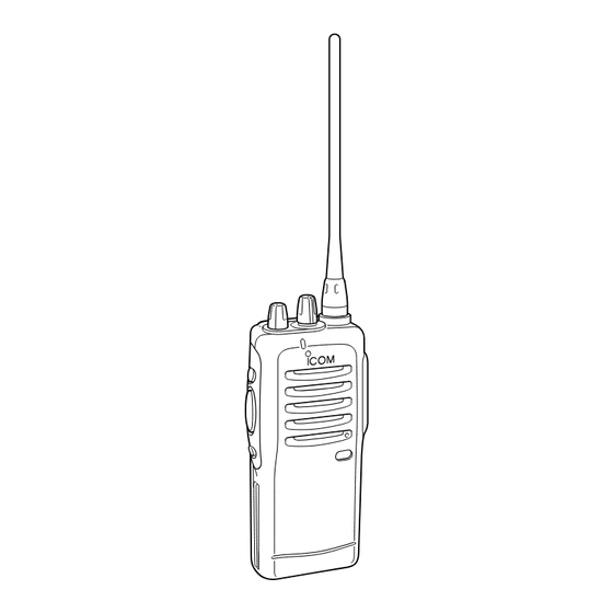
INSTRUCTION MANUAL
UHF GMRS TRANSCEIVER
iF21GM
This device complies with Part 15 of the FCC rules. Oper-
ation is subject to the following two conditions: (1) This de-
vice may not cause harmful interference, and (2) this
device must accept any interference received, including in-
terference that may cause undesired operation.
Advertisement
Table of Contents

Subscribe to Our Youtube Channel
Related Manuals for Icom IC-F21GM


Summary of Contents for Icom IC-F21GM
- Page 1 INSTRUCTION MANUAL UHF GMRS TRANSCEIVER iF21GM This device complies with Part 15 of the FCC rules. Oper- ation is subject to the following two conditions: (1) This de- vice may not cause harmful interference, and (2) this device must accept any interference received, including in- terference that may cause undesired operation.
-
Page 2: Safety Training Information
This radio has been tested and complies with the FCC RF expo- sure limits for “Occupational Use Only”. In addition, your Icom radio complies with the following Standards and Guidelines with regard to RF energy and electromagnetic energy levels and evaluation of such levels for exposure to humans: •... -
Page 3: Electromagnetic Interference/Compatibility
• ALWAYS keep the antenna at least 2.5 cm (1 inch) away from the body when transmitting and only use the Icom belt-clips, listed in p. 22, when attaching the radio to your belt, etc., to ensure FCC RF ex- posure compliance requirements are not exceeded. - Page 4 Your Icom F21GM operates on GMRS frequencies (Plus 7 channels shared with FRS ). GENERAL MOBILE RADIO SERVICE (GMRS) GMRS is a two-way personal radio service available to an individual (one man or one woman) to facilitate the activities of the individ- ual's immediate family members.
-
Page 6: Foreword
The use of non-Icom battery packs/chargers may impair transceiver performance and invalidate the warranty. FCC caution: Changes or modifications to this transceiver, not expressly approved by Icom Inc., could void your authority to op- erate this transceiver under FCC regulations. -
Page 7: Table Of Contents
6 OPTION ........23-24 Icom, Icom Inc. and the Icom Incorporated (Japan) in the United states, the United King- dom, Germany, France, Spain, Russia and/or other countries. -
Page 8: Panel Description
PANEL DESCRIPTION ‘ ‘ Switches, controls, keys and connectors ↔ CH16 Speaker • HM-75A (OPTION) Mic A Mic UP Mic B Mic Down... - Page 9 q CHANNEL SELECTOR/SW [CH] (p. 14) Turn to select CH1 to CH16. w VOLUME CONTROL [OFF/VOL] Turns power ON and adjusts the audio level. e MONITOR (Audi) key [MONI] (p. 21) • Push and hold to open the noise/tone squelch. •...
-
Page 10: Led Indicator
PANEL DESCRIPTION ‘ ‘ LED indicator The TX/RX indicator LED indicates informa- tion in several ways as follows; (Ref.; R=Red, G=Green) • TX: Turns Red while transmitting a signal. • RX: Turns Green while receiving a signal. • Low BATT1: You should charge the battery. (blinks slowly) •... -
Page 11: Accessories
ACCESSORIES ‘ ‘ Accessory attachment D Supplied accessories The transceiver comes supplied with the following accessories. q Flexible antenna w Belt clip D Antenna The antenna screws onto the transceiver as illustrated at right. D Belt clip Attach the belt clip to the transceiver as illustrated below. -
Page 12: Battery Packs
BATTERY PACKS ‘ ‘ Battery pack replacement Before replacing the battery pack, the volume control MUST be ro- tated fully counterclockwise, until a click is heard, to turn the power OFF. • Push the battery release for- ward, then pull the battery pack upward with the trans- ceiver facing you. -
Page 13: Battery Cautions
‘ ‘ Battery cautions • CAUTION! NEVER short the terminals of the battery pack (or charging terminals of the transceiver). Also, current may flow into nearby metal objects such as a necklace, so be careful when plac- ing battery packs (or the transceiver) in handbags, etc. Simply carrying with or placing near metal objects such as a neck- lace, etc. -
Page 14: Battery Charging
BATTERY PACKS ‘ ‘ Battery charging D Rapid charging with the BC-144+AD-99 The optional BC-144 provides rapid charging of optional battery packs. The following are additionally required: • One AD-99 (depends on version.). • An AC adaptor (may be supplied with the BC-144 depending on version). - Page 15 D Rapid charging with the BC-144+AD-99 BP-209, BP-210 or BP-222 attached to the transceiver. AC adaptor BC-145A/E/V/UK Charging indicator D D Spacer combination. • Be sure to attach the spacer (Spacer B/C) to the adaptor (Spacer A) with the orientation as il- lustrated in the diagram at right.
- Page 16 BATTERY PACKS D Rapid charging with the BC-121+AD-94 (#11) The optional BC-121 allows up to 6 battery packs to be charged si- multaneously. The following are additionally required. • Six AD-94 (#11) (Some versions require additional AD-99s). • An AC adaptor (may be supplied with the BC-121 depending on version).
-
Page 17: Charging Note
‘ ‘ Charging NOTE Prior to using the transceiver for the first time, the battery pack must be fully charged for optimum life and operation. • Recommended temperature range for charging: +10°C to +40°C (50°F to 140°F). • Use the supplied charger or optional charger (BC-119/BC-121/BC- 144 for rapid charging, BC-146 for regular charging) only. -
Page 18: Battery Case (Option)
BATTERY PACKS ‘ ‘ Battery case (Option) When using a BP-208 OPTIONAL BATTERY CASE attached to the transceiver, install 6 AA (R6) size alkaline batteries as illustrated below. NOTE: Output power is automatically reduced to 1 W to retain suffi- cient power in case of an emergency, etc. -
Page 19: 4 S S E E T T M M O O D D E E
‘ ‘ Set mode Set mode is used for programming infrequently changed values or conditions of functions. • All settings performed with [CH selector], [OFF/VOL], [MONI], [PTT] and [W/N] keys. D D SELECTING POWER The RF output can be selected from one of 3 modes. - Page 20 CHAPTER CONTINUED D D SELECTING RF OUTPUT POWER The transceiver has 3 output power levels to suit your operating re- quirements. Low out put power settings during short-distance com- munications may reduce the possibility of interference to other stations, and will reduce current consumption. q While pushing and holding [PTT], [MONI], turn [OFF/VOL] to power ON.
- Page 21 • Frequency channel list Rx/Tx Freq.* 462.5500 462.5750 462.6000 462.6250 462.6500 462.6750 462.7000 462.7250 462.5625 462.5875 462.6125 462.6375 462.6625 462.6875 462.7125 Auto Scan : Simplex operation/Duplex receive frequency : Duplex transmit frequency Wide/Narrow: Wide FM/Narrow FM (default) CHAPTER CONTINUED Wide/Narrow Tx Freq.* 467.5500 Narrow...
- Page 22 SET MODE D D SETTING THE CTCSS TONE FREQUENCY This transceiver is equipped with 52 CTCSS codes. (See right.) CTCSS operation provides communication with silent standby since you will only receive calls from group members using the same CTCSS number. You can assign different numbers to CH 1 to CH 15 independently.
- Page 23 • CTCSS tone code list Freq.* 67.0 69.3 71.0 71.9 74.4 77.0 79.7 82.5 85.4 88.5 91.5 94.8 97.4 100.0 103.5 : EIA/TIA standard code (Recommended to use these.) Freq.* Freq.* 171.3 107.2 173.8 110.9 177.3 114.8 179.9 118.8 183.5 123.0 186.2 127.3...
- Page 24 SET MODE D D SETTING THE CTCSS TONE FREQUENCY (continued) • CTCSS confirmation beep Push [PTT] 1 (Once) 2 (Twice) 3 (Third) 4 (Fourth) G; Single beep ; Long beep D D SETTING THE DTCS CODE This transceiver is equipped with 83 DTCS codes. DTCS operation provides communication with silent standby since you will only re- ceive calls from group members using the same DTCS number.
- Page 25 • Confirmation beep is emitted. (See p. 17) !0 Push [PTT] once more, if you want to use Inverse mode. !1 Push [MONI] to complete the setting. • Confirmation beep is emitted. (See p. 17) !2 Turn the power OFF, and then ON again. [Example] To assign code ‘261 (normal)’...
- Page 26 SET MODE D D CTCSS FIND This transceiver can detect the CTCSS tone frequency in the re- ceived signal. By monitoring a signal that is being transmitted from the other station, you can determine the tone frequency required to communicate with them. This function very useful when you are going to communicate with unknown CTCSS channel number stations.
-
Page 27: Operation
‘ ‘ Receiving and transmitting NOTE: Transmitting without an antenna may damage the trans- ceiver. See p.4 for antenna attachment. Turn power ON as described on p. 2. Program the SIMPLEX/DUPLEX OPERATION and CTCSS /DTCS tone number (select CH 0 if you will not use the CTCSS function) before operation. - Page 28 OPERATION D D MONITOR AUDIBLE FUNCTION The monitor function allows you to open the transceiver’s squelch manually to check whether a channel is busy or not. The trans- ceiver has 2 conditions for receive standby: All signals are received Only signals con- taining the proper tone are received D D TIME-OUT TIMER...
-
Page 29: Setting Squelch Level
‘ ‘ Setting squelch level The squelch circuit mutes the received audio signal depending on the signal strength. Scan proceeds in sequence from lower channel to higher channel numbers. q While pushing [PTT] and [W/N], turn the transceiver’s power on to enter the squelch adjustment mode. -
Page 30: Option
OPTION ‘ ‘ Options D D BATTERY PACKS • BP-208 BATTERY CASE Allows a set of Alkaline batteries to operate the handheld when charging the rechargeable battery or in emergencies, etc. 6 AA (R6) cells are required. • BP-209 Ni-Cd BATTERY PACK 7.2 V/1100 mAh Ni-Cd battery pack, allows more than 8 hours op- eration. -
Page 31: Option
D D OTHER OPTIONS • HM-46L/HM-75A/HM-131L SPEAKER-MICROPHONES Combination speaker-microphone that provides convenient oper- ation while hanging the transceiver from your belt. HM-75A has programmable function key Mic Up, Mic Down, Mic A, Mic B. HM-131L has moisture proof construction. • HS-51 HEAD SET Allows you hands-free operation. - Page 32 Count on us! A-6023D-1GM-q Printed in Japan 1-1-32 Kamiminami, Hirano-ku, Osaka 547-0003 Japan © 2001 Icom Inc.
Need help?
Do you have a question about the IC-F21GM and is the answer not in the manual?
Questions and answers