
Related Manuals for Valet 551T

Summary of Contents for Valet 551T
- Page 1 ® Model 551T Installation Guide ® © 2000 Directed Electronics, Inc. Vista, CA N551T 12-00...
-
Page 2: Table Of Contents
Bitwriter™, Code Hopping™, DEI®, Doubleguard®, ESP™, FailSafe®, Ghost Switch™, Learn Routine™, Nite-Lite®, Nuisance Prevention Circuitry®, NPC®, Revenger®, Silent Mode™, Soft Chirp®, Stinger®, Valet®, Vehicle Recovery System®, VRS®, and Warn Away® are all Trademarks or Registered Trademarks of Directed Electronics, Inc. -
Page 3: What Is Included
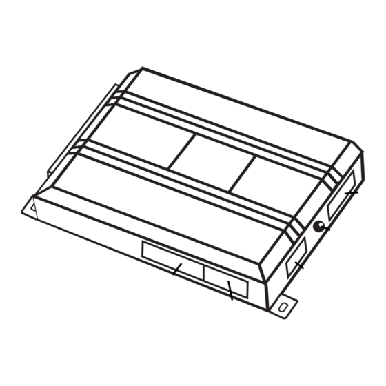
what is included I The control module (see diagram) I The plug-in program switch I A hood pinswitch I A relay satellite I A toggle override switch I An 8-pin primary wiring harness I A 6-pin remote wiring harness I A 5-pin relay satellite harness I A warning sticker 5-pin Relay Satellite... -
Page 4: Warning! Safety First
warning! safety first The following safety warnings must be observed at all times: I Due to the complexity of this system, installation of this product must only be performed by an authorized DEI dealer. I When properly installed, this system can start the vehicle via a command signal from the remote control transmitter. -
Page 5: Installation Points To Remember
installation points to remember Before beginning the installation: IMPORTANT! This product is designed for fuel-injected, automatic transmission vehicles only. Installing it in a standard transmission vehicle is dangerous and is contrary to its intended use. I Please read this entire installation guide before beginning the installation. The installation of this remote start system requires interfacing with many of the vehicle’s systems. -
Page 6: Finding The Wires You Need
finding the wires you need IMPORTANT! Do not use a 12V test light or logic probe/computer safe test light to locate these wires! All testing described in this manual assumes the use of a digital multimeter. obtaining constant 12V We recommend two possible sources for 12V constant: The (+) terminal of the battery, or the constant 12V supply to the ignition switch. -
Page 7: Finding The 12V Switched Ignition Wire
5. Cut the wire you suspect of being the starter wire. 6. Attempt to start the car. If the starter engages, reconnect it and go back to Step 3. If the starter does not turn over, you have the right wire. finding the 12V switched ignition wire The ignition wire is powered when the key is in the run or start position. -
Page 8: Finding The Tachometer Wire
How to find a (+) parking light flash wire with your multimeter: 1. Set to DCV or DC voltage (12V or 20V is fine). 2. Attach the (-) probe of the meter to chassis ground. 3. Probe the wire you suspect of being the parking light wire. Usually, the area near the headlight/parking light switch is an excellent area to start, as is the kick panel. -
Page 9: Finding The Wait-To-Start Bulb Wire For Diesels
finding the wait-to-start bulb wire for diesels In diesel vehicles it is necessary to interface with the wire that turns on the WAIT TO START light in the dash- board. This wire illuminates the bulb until the vehicle’s glow plugs are properly heated. When the light goes out the vehicle can be started. -
Page 10: Primary Harness (H1), 8-Pin Connector Wiring Diagram
primary harness (H1) wiring diagram ______ H1/1 BLACK (-) CHASSIS GROUND INPUT ______ H1/2 WHITE/BLUE (-) ACTIVATION INPUT ______ H1/3 LIGHT GREEN/BLACK (-) FACTORY DISARM/SPECIAL ACCESSORY ______ H1/4 YELLOW (+) IGNITION (OUTPUT TO SECURITY SYSTEM) ______ H1/5 WHITE (-) LIGHT FLASH OUTPUT ______ H1/6 GRAY/BLACK... -
Page 11: Remote Start Harness (H2), 6-Pin Connector Wiring Diagram
remote start harness (H2) wiring diagram ______ BLUE (-) 200 mA STATUS/FACTORY SECURITY REARM OUTPUT H2/1 ______ BLUE/BLACK (-) 200 mA THIRD IGNITION OUTPUT H2/2 ______ GRAY (-) HOOD PINSWITCH SHUTDOWN WIRE H2/3 ______ BROWN (+) BRAKE SWITCH SHUTDOWN WIRE H2/4 ______ VIOLET/WHITE... - Page 12 to a keyless entry system. This wire can also be connected to an optional momentary switch to activate the remote start system. H1/3 LIGHT GREEN/BLACK (-) factory security disarm/special accessory output This wire sends a negative pulse every time the remote start is activated. This can be used to pulse the disarm wire of the vehicle's factory anti-theft device.
- Page 13 H1/5 WHITE (-) light flash output This wire provides a (-) 200mA output to flash the parking lights during remote start operation. This is suitable for driving (-) light control wires in Toyota, Lexus, BMW, some Mitsubishi, some Mazda models, etc. If the vehicle has a positive parking light circuit a relay must be used to flash the parking lights.
- Page 14 © 2000 Directed Electronics, Inc.
-
Page 15: Relay Satellite Key Switch Interface
relay satellite key switch interface The heavy gauge wires leading from the relay satellite are used to energize high current circuits in the vehicle. It is crucial that these connections are made correctly so that they are capable of handling the current demands. For this reason, scotch locks, T-taps and other such connectors should not be used. -
Page 16: Remote Start Harness (H2), 6-Pin Connector
remote start harness (H2), 6-pin connector H2/1 BLUE status/factory security rearm output This output is programmable. If programmed for status output, the wire will supply an output at all times the remote start is operating. If programmed for factory security rearm, the wire will supply a pulse whenever the remote start times out or is shut down using the transmitter. -
Page 17: Neutral Safety Switch Interface
H2/6 BLACK/WHITE neutral safety switch input Connect this wire to the toggle (override) switch as shown in Figure A. Connect the other wire from the toggle switch to the PARK/NEUTRAL switch in the vehicle. This wire will test with ground with the gear selector either in PARK or NEUTRAL. - Page 18 Vehicles with the neutral safety switch built into the column shifter require that the shifter be placed in park in order to remove the keys from the ignition. As a result, it is possible to use the key-in-ignition sense switch to prevent remote starting if the keys are in the ignition.
-
Page 19: Passenger Cars
general motors trucks, SUVs, and column shifting passenger cars pre-1996 dodge dakota pickups with 2.5 liter motors © 2000 Directed Electronics, Inc. -
Page 20: Bypassing Gm Vehicle Anti-Theft Systems (Vats)
bypassing GM vehicle anti-theft systems (VATS) Vehicles with the GM VATS (Pass Key) systems have a resistor embedded in the ignition key. If the VATS decoder module does not measure the proper resistance when the vehicle is started, the starter and fuel pump may be disabled for up to ten minutes. -
Page 21: 1995 And Newer Vehicle Anti-Theft Systems (Immobilizers)
1995 and newer vehicle anti-theft systems 1995 and newer vehicle anti-theft systems (immobilizers) require a bypass module. The bypass module allows for easy interfacing, while still maintaining the OEM system’s integrity. passlock I and passlock II (PL-1 and PL-2) The Passlock I and Passlock II systems can be found in the following General Motors vehicles: I ‘95 and newer Cavalier and Sunfire I ‘96 and newer Achieva, Grand Am, and Skylark I ‘97 and newer Intrigue, Malibu, and Cutlass... -
Page 22: Optional Anti-Grind Relay
of the system, the vehicle will be allowed to start. Most of these transponder-based systems can be bypassed using p/n 555U. Some may require additional parts from the vehicle manufacturer. Consult you dealer for the applications. For most Ford PATS transponders, p/n 555F can be used, except for the following vehicles, which will require p/n 555U: ‘97 and newer Mark VII, and 2000 and newer Taurus/Sable, Contour/Mystique and Focus. -
Page 23: Plug-In Program Switch
plug-in program switch The Program switch plugs into the blue two-pin connector. tach learning To learn the tach signal: Start the vehicle with the key. DRW-96 Within 5 seconds, press and HOLD the Program switch. The LED will light constant when the tach signal is learned. If the LED does not light bright red, the unit did not learn the tach signal. -
Page 24: Internal Programming Jumper
internal programming jumper digital tach threshold on/off Remove the control module case cover to access the jumper. In most cases, this jumper can be left in the OFF position. Some new vehicles use less than 12 volts in their ignition systems. The unit may have trouble learning the tach signal in these vehicles. -
Page 25: Operating-Settings Learn Routine
operating settings learn routine The System Features Learn Routine dictates how the unit operates. It is possible to access and change any of the feature settings using the Program switch. The programmable operating settings of this unit can be changed whenever necessary through the computer- based Learn Routine. -
Page 26: Features Menu
The learn routine will be exited if: I The ignition is turned on. I The Program switch is pressed too many times. I More than 25 seconds elapses between programming steps. features menu The factory default settings are indicated below in bold. FEATURE NUMBER DEFAULT - LED ON SETTING... - Page 27 2 TACH WIRE SENSE/VOLTAGE SENSE: If the tachometer signal wire is used, this feature must be left in the default (tach wire connected) setting. If programmed to the voltage sense setting, the unit will crank the starter for a preset time that can be programmed in Feature 5. Once the starter has been engaged, the system will check the voltage level to verify the engine is running.
-
Page 28: Shutdown Diagnostics
shutdown diagnostics The unit has the ability to report the cause of the last shutdown of the remote start system. To enter diagnos- tics mode: Turn the ignition off. Press and hold the Program switch. Turn the ignition on and then off. Release the Program switch. -
Page 29: Timer Mode
timer mode This unit can be programmed to start and run the engine every three hours. The engine will run for the pro- grammed run time and then shut down. After three hours, the unit will restart the engine. A maximum of six cycles can occur. -
Page 30: Troubleshooting
a. Make sure the hood is closed and no other shutdown circuits are active. b. Set the emergency brake. c. Turn the ignition key to the run position but do not start the engine. d. Put the vehicle in Drive (D). e. - Page 31 I The vehicle starts, but immediately dies. 1. Does the vehicle have an immobilizer? The vehicle’s immobilizer will cut the fuel and/or spark during unau- thorized starting attempts. 2. Is the remote start programmed for voltage sense? If so, the start time may not be set high enough, or you may have to adjust the voltage threshold in programming.
-
Page 32: Wiring Quick Reference Guide
© 2000 Directed Electronics, Inc.
Need help?
Do you have a question about the 551T and is the answer not in the manual?
Questions and answers