Advertisement
Totaline
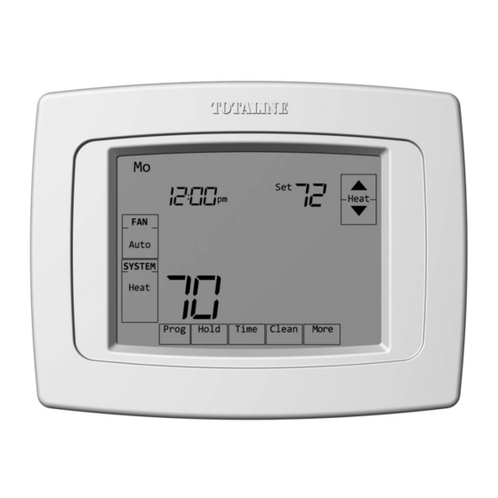
Deluxe 1H/1C and 3H/2C
®
Touchscreen Programmable P340 Series Thermostats
This manual covers the following models
• P340-1110: For 1 Heat/1 Cool systems
• P340-1320: For up to 2 Heat/2 Cool heat/cool systems or up to 3 Heat/2
Cool Heat Pump Systems
System Types
• Gas, oil, or electric heat with air
conditioning
• Warm air, hot water, high efficiency
furnaces, heat pumps, steam, gravity
This thermostat contains a Lithium battery which may contain Perchlorate material.
Perchlorate Material—special handling may apply,
See www.dtsc.ca.gov/hazardouswaste/perchlorate
570-219
® U.S. Registered Trademark.
All rights reserved.
• Heat only — two-wire systems, power
to open and close zone valves (Series
20), and normally open zone valves
• Heat only with fan
• Cool only
• 750 mV heating systems
Need Help?
Visit www.Totaline.com
Installation
Guide
69-2268-03
Advertisement
Table of Contents

Related Manuals for TOTALINE Deluxe 1H


Summary of Contents for TOTALINE Deluxe 1H
- Page 1 Installation Guide Totaline Deluxe 1H/1C and 3H/2C ® Touchscreen Programmable P340 Series Thermostats This manual covers the following models • P340-1110: For 1 Heat/1 Cool systems • P340-1320: For up to 2 Heat/2 Cool heat/cool systems or up to 3 Heat/2 Cool Heat Pump Systems System Types • Heat only — two-wire systems, power to open and close zone valves (Series • Gas, oil, or electric heat with air 20), and normally open zone valves conditioning • Heat only with fan • Warm air, hot water, high efficiency • Cool only furnaces, heat pumps, steam, gravity • 750 mV heating systems...
-
Page 2: Wallplate Installation
Installation Guide Wallplate installation Grasp top and 1. Separate wallplate from thermostat. bottom of wallplate and pull to remove 2. Mount wallplate as shown below. from thermostat. Drill 3/16” holes for drywall. Drill 7/32” holes for plaster. WIRE M29131 WALL OPENING MOUNTING SCREWS (2) WALL ANCHORS (2) (PROVIDED WITH THERMOSTAT) M29130 Must be installed by a trained, experienced technician • Read these instructions carefully. Failure to follow these instructions can damage the product or cause a hazardous condition. CAUTION: ELECTRICAL HAZARD Can cause electrical shock or equipment damage. Disconnect power before beginning installation. -
Page 3: Power Options
P340 Series Power options – + – M29128 M28653 Insert supplied batteries for For 24VAC primary power, connect common primary or backup power. side of transformer to “C” terminal. Wiring Remove factory-installed jumper Push excess wire back into the wall opening. Plug only for two-transformer systems. wall opening with non-flammable insulation. M28655 M28654 Terminal Designations Shaded areas below apply only to P340-1320. Conventional Terminal Letters: Heat Pump Terminal Letters: Heating power. Connect to secondary side of Heating power. Connect to secondary heating system transformer. side of heating system transformer. Cooling power. Connect to secondary Cooling power. Connect to secondary side of cooling system transformer. side of cooling system transformer. Common wire from secondary side of Common wire from secondary side of cooling transformer (if 2 transformers). - Page 4 Installation Guide Wiring Wiring guide—conventional systems Shaded areas below apply only to P340-1320. 1H/1C System (1 transformer) 1H/1C System (2 transformers) Power [1] Power (cooling transformer) [1, 2] [R+Rc joined by jumper] Power (heating transformer) [1, 2] Heat relay Heat relay Compressor contactor Compressor contactor Fan relay Fan relay 24VAC common [3] 24VAC common [3, 4] Optional outdoor/remote sensor Optional outdoor/remote sensor Optional outdoor/remote sensor Optional outdoor/remote sensor Heat Only System Heat Only System With Fan Power [1] Power [1] [R+Rc joined by jumper]...
- Page 5 P340 Series Wiring Wiring guide—heat pump systems Shaded areas below apply only to P340-1320. 1H/1C Heat Pump (no auxiliary heat) 2H/2C Heat Pump (no auxiliary heat) Power [1] Compressor 2 relay [R+Rc joined by jumper] Power [1] Changeover valve [5] [R+Rc joined by jumper] Compressor relay Changeover valve [5] Fan relay Compressor 1 relay 24VAC common [3] Fan relay Optional outdoor/remote sensor 24VAC common [3] Optional outdoor/remote sensor Optional outdoor/remote sensor Optional outdoor/remote sensor 2H/1C Heat Pump (with auxiliary heat) 3H/2C Heat Pump (with auxiliary heat) Equipment monitor [6, 7] Emergency heat relay [8]...
-
Page 6: Set Date And Time
Installation Guide Remove tab and mount thermostat Remove tab. Align pins on back of thermostat with slots in wallplate, then push gently until thermostat snaps into place. M29129 Set date and time Press st Press st to set year to set time Press st to set date Press st to set month M29125 Press DONE to save changes. Press DONE to save and exit. - Page 7 P340 Series Installer setup Function Setting Press st to Press st to select function change setting Press DONE to exit & save settings. M28652 Setup functions Settings & Options (factory default in bold) Shaded areas below apply only to P340-1320 0120 Year 20 (2000-2078) (first two digits) 21 (2101-2178) 0130 Year 06 (2006)
- Page 8 Installation Guide Installer setup Setup functions Settings & Options (factory default in bold) Shaded areas below apply only to P340-1320. 0240 First stage heat Gas or oil furnaces of less than 90% efficiency cycle rate (CPH= Steam or gravity systems cycles per hour) Hot water systems & furnaces of 90%+ efficiency Electric furnaces [Other options: 2, 4, 6, 7, 8, 10, 11, 12 CPH] 0250 Second stage heat Gas or oil furnaces of less than 90% efficiency cycle rate (CPH) Steam or gravity systems...
- Page 9 P340 Series Installer setup Setup functions Settings & Options (factory default in bold) 0500 Furnace filter change reminder 10-day run time (about 1 month) 30-day run time (about 3 months) 60-day run time (about 6 months) 90-day run time (about 9 months) 120-day run time (about 1 year) 365-day run time (about 3 years) 0510 Humidifier pad change reminder 90 calendar days 180 calendar days 365 calendar days 0520 UV lamp change reminder 365 calendar days 0530 Early Recovery ** See page 11 0540 Program periods 4 program periods (Wake, Leave, Return, Sleep) 2 program periods (Wake, Sleep)
-
Page 10: Installer System Test
Installation Guide Installer system test During installer setup, press t Press st to Press st to repeatedly until “Test” appears. select test change status Test number M29127 System status Press DONE to terminate testing. Shaded areas below apply only to P340-1320. System test System status Cooling system Compressor and fan turn off Compressor and fan turn on Second stage compressor turns on Fan system Fan turns off Fan turns on Heating system... -
Page 11: Special Functions
P340 Series Special functions Shaded areas below apply only to P340-1320. Auto Changeover (Setup Function 0300): When set to Auto, the thermostat automatically selects heating or cooling depending on the indoor temperature. Heat and cool settings must be at least 2 degrees apart. Remote Sensor (Setup Function 0340): If an optional outdoor sensor is installed, the thermostat can display the outside temperature. If an optional remote indoor sensor is installed, the thermo- stat will display the temperature at the sensor location (the internal sensor in the thermostat is not used). Early Recovery (Setup Function 0530): Allows the thermostat to “learn” how long the furnace and air conditioner take to reach programmed temperature settings, so the temperature is reached at the scheduled time. Compressor Protection (Setup Function 0580): Forces the compressor to wait a few minutes before restarting, to prevent damage. During this time, the message “Wait” flashes on the display. Heat Pump Compressor Lockout (with fossil-fuel backup): If the thermostat is installed with an optional outdoor sensor, you can select a compressor lockout temperature (Function 0350). When the outdoor temperature is below the lockout temperature, only the auxiliary heat operates. When the outdoor temperature is above the lockout temperature, only the compressor operates. Heat Pump Auxiliary Lockouts (with electric heat backup): If the thermostat is installed with an optional outdoor sensor, you can select a compressor lockout temperature (Function 0350) and/or an auxiliary heat lockout temperature (Function 0360). When the outdoor temperature is below the compressor lockout temperature, only the auxiliary heat operates. When the outdoor temperature is above the auxiliary lockout temperature, only the compressor operates. If the outdoor temperature is between the compressor and auxiliary lockout temperatures, both the compressor and auxiliary heat can operate. -
Page 12: Specifications
Installation Guide Specifications Temperature Ranges Electrical Ratings • Heat: 40° to 90°F (4.5° to 32°C) Terminal Voltage (50/60Hz) Running Current • Cool: 50° to 99°F (10° to 37°C) W Heating 20-30 Vac 0.02-1.0 A Operating Ambient Temperature (Powerpile) 750 mV DC 100 mA DC • 0° to 120°F (-18° to 48.9°C) W2 Heating 20-30 Vac 0.02-0.6 A Shipping Temperature Y Cooling 20-30 Vac 0.02-1.0 A • -30° to 150°F (-34° to 66°C) Y2 Cooling 20-30 Vac 0.02-0.6 A Operating Relative Humidity Aux Auxiliary heat 20-30 Vac 0.02-1.0 A...
Need help?
Do you have a question about the Deluxe 1H and is the answer not in the manual?
Questions and answers