
Related Manuals for Baer UniMod GSM-4

Summary of Contents for Baer UniMod GSM-4
-
Page 1: Unimod Gsm
UniMod GSM-4 Modem User Manual E109102214063 Bär Industrie-Elektronik GmbH Rathsbergstr. 23 D-90411 Nürnberg Germany Phone : +49 911 970590 Fax: +49 911 9705950 Internet: www.baer-gmbh.com... - Page 2 UniMod GSM-4 COPYRIGHT Copyright © 2014 BÄR Industrie-Elektronik GmbH. All rights, including those originating from translation, (re)-printing and copying of this document or parts thereof are reserved. No part of this manual may be copied or distributed by electronic, mechanic, photographic or indeed any other means without prior written consent of BÄR Industrie-Elektronik GmbH.
-
Page 3: Table Of Contents
UniMod GSM-4 Table of Contents Page General ..........................5 Requirements ......................5 Safety Precautions for the User ..................6 Power Supply Unit ......................7 Interfaces.......................... 8 Display ..........................10 Installation Hints ......................11 Programming the Modem ....................12 Testing the Connection ................... 18 Parity Error (7E1) .................... -
Page 4: Unimod Gsm
UniMod GSM-4... -
Page 5: General
Service) and short messages (SMS). The universal radio modem UniMod GSM-4 is supposed for remote inquiry of measurement data of any kind, especially however for telecounting applications. The UniMod GSM-4 supports in the operation mode GPRS the meter data communication according to DIN 43863-4 (IP-Telemetry). Requirements The UniMod GSM-4 can be used in any EGSM 850/900/1800/1900 MHz network with an arbitrary number of providers. -
Page 6: Safety Precautions For The User
Precautions in the event of loss/theft of the Cellular Engine and the SIM card If your UniMod GSM-4, your SIM card or both go missing, notify your net- work operator immediately in order to avoid misuse. -
Page 7: Power Supply Unit
UniMod GSM-4 Power Supply Unit The modem is equipped with a built-in, low-loss switched power supply, which enables it to operate on a wide-range AC or DC supply voltage. 80VAC to 270VAC (50/60Hz) or 60VDC to 375VDC alternative (with additional board): 10VDC to 36VDC (0,8A) -
Page 8: Interfaces
Communication is possible with many standard protocols, like SCTM, LSV1, DLMS, IEC1107, IEC60870, M-Bus, Modbus (transparent reading) etc. The following internal (on-board) interfaces in UniMod GSM-4 are available: R T S 20mA (CS, current loop) active for 4 devices max. - Page 9 UniMod GSM-4 In the UniMod GSM-4 modem an additional slot is available for another in- terface module. For this slot the following module types are available (instal- lation: see page 32): R T S 20mA (CS, current loop) active (for 4 devices max.) or passive;...
-
Page 10: Display
- in GPRS mode: IPT or BAER: DCD lights, when the modem is logged to the GPRS-Bridge fixed IP address: DCD lights, when a remote modem has built a data link to the UniMod GSM4; ... -
Page 11: Installation Hints
The SIM card is now ready to use. 3) After that connect the antenna to the UniMod GSM-4 using the FME plug. At last (important!) connect it to the supplying power. -
Page 12: Programming The Modem
UniMod GSM-4 Programming the Modem Before installing the modem it has to be programmed in order to meet the demands. The baud rate and data format for connecting the target device and the transmission mode and transmission rates must be adjusted. On... - Page 13 UniMod GSM-4 B) The parametering adapter with RS232 interface, which can be plugged instead of an interface module. This adapter can be ordered as accessory (Order No.: #9177). 1) First set the switch to position "GSM", as shown in the picture.
- Page 14 UniMod GSM-4 Now you have to set your terminal program to the fixed, local data rate and data format of the UniMod. (Default values: 9600 Bit/sec, 7,E,1) Use one of the AT commands (e.g. ATS0?, ATI, AT&V) in order to check whether the modem answers.
- Page 15 UniMod GSM-4 Following some examples of AT commands (the answers depend upon the respective firmware version): Request Answer Description DTE SPEED : 19200 at&v Inquires current configuration DTE FORMAT : AUTO GSM DATA MODE : Not Transparent AUTOBAUD : +IPRxxx00=NO...
- Page 16 UniMod GSM-4 Request Answer Description 71 - 9600 bps (V.110 or X.31 flag stuffing) 75 - 14400 bps (V110 or X.31 flag stuffing), name n=0 for asynchronous mode, element e=0 for transparent or e=1 for non transparent transmission e.g.. at+cbst=0,0,1 (for autobauding, asyn- chronous mode, non transparent) at&f...
- Page 17 Insert SIM card Establish connection PC to modem (e.g. using the RS232 cable) Switch on UniMod GSM-4, wait 50 to 60 sec: till first INF-LED is on Start the UniModSet software Read the equipment configuration: ...
-
Page 18: Testing The Connection
In the most cases a switch of the UniMod GSM-4 data format from "7E1" to "8N1" is able to bring fast and easy help. Using this configuration data retrieval from most meters is possible in the format "7E1"... -
Page 19: Additional Functions
UniMod GSM-4 Additional Functions Reset Optional it is possible to activate the time-controlled modem-reset. With this turned on the modem (GE864-Module) is regularly deactivated by the inter- nal firmware. After the reset it logs on to the PLMN (Public Land Mobile Network) again. -
Page 20: Signal Quality
UniMod GSM-4 Signal Quality When the modem operates in CSD mode (!) the INF-LEDs’ show the cur- rent field strength of the GSM signal. When the display is updated (every three seconds) the first INF-LED flickers shortly. The second and third INF- LED on / :... -
Page 21: Sms Function
UniMod GSM-4 SMS Function Optional it is possible to activate SMS. This function is monitoring of on/off state changes of SMS input (terminals 8/GND and 9/UE), possible in CSD mode and GPRS mode: Interface RS232: Function DCD/DTR SMS: Function UE/UA, Standard... -
Page 22: Automatic Baud Rate Adaption
This baud rate is the restored after each power outage. In order to use “Automatic Baud Rate Adaption” the jumpers UE and UA at the UniMod GSM-4 must be set as shown below to use the control input UE (terminal 8/GND and 9/UE):... - Page 23 8/GND and 9/UE) must be short-cut for at least 5 seconds. After that the leftmost INF-LED flashes three times and the detection is started. The UniMod GSM-4 checks these baud rates in order: 19200, 9600, 4800, 2400, 1200, 600 und 300 Bd. Before the baud rate is switched the left INF- LED flashes three times.
- Page 24 UniMod GSM-4 You can enable/disable these functionality using function “automatic baud rate adaption (IEC 62056-21/61107 local) in the UniModSet program. See below: Function “Automatic baud rate adaption” doesn’t work at the same time with Note: “SMS function”...
-
Page 25: Temporary Baud Rate Switching
(for GPRS connection after a reset only). ► The character sequence {[%]} has been chosen because it is quite ex- otic and should never appear in regular communication to meters. Note: For correct working set the data format at the UniMod GSM-4 to 8N1. -
Page 26: Gprs: More Plmns
Since the firmware version #90 is possible to set more mobile network pro- viders (PLMN: Public Land Mobile Network): When the field “PLMN-Code” is empty, the UniMod GSM-4 uses the first available mobile network. After clicking the “More PLMN’s” button, further mobile networks can be en-... -
Page 27: Gprs: Fixed Ip Address
UniMod GSM-4 GPRS: Fixed IP Address Settings for fixed IP address and network port (incl. firewall): Settings for firewall: Examples: Firewall = 0.0.0.0 and network mask = 0.0.0.0: connection to all IP ad- dresses is possible (accept all); Firewall = 192.168.1.1 and network mask = 255.255.255.255: only connec- tion to the IP address 192.168.1.1 is possible;... -
Page 28: Gprs: Test Mode
UniMod GSM-4 GPRS: Test Mode Since the firmware version #90 is possible to activate a test mode: shows information about log on to the GPRS network via service interface: Note: use only for testing, deactivate please this function after the tests! 8.10... - Page 29 UniMod GSM-4 Local: When doing a firmware update via RS232 service interface it is advisable to remove or disable the SIM card in the modem. Mobile: When doing a firmware update remotely via GSM/PSTN/GPRS connection the data format must be set to 8N1 (set option “Read”, see picture below). If the remote modem is set to 7E1 then the option “Remote 7E1”...
-
Page 30: Technical Data
Fully type approved conforming with R&TTe directive CE, GCF, FCC, PTCRB, IC, Anatel Approval: CE0168 or CE0889 GSM band: Quad-Band EGSM 850/900/1800/1900 MHz GPRS: Multi-slot class 10: downlink 4 timeslots, uplink 2 timeslots Mobile station class B M2M-Transmision: DIN 43863-4 (IP-Telemetry) or BAER- Protocol... - Page 31 Hayes Standard-AT, GSM 07.07, GSM 07.05 References: European Telecommunications Standards Institute, www.etsi.org Extent of delivery: - UniMod GSM-4 including interface module as ordered - Standard antenna: magnetic foot antenna with FME (f), 0dB, cable: 2,5m RG174 - Operation manual Accessories:...
-
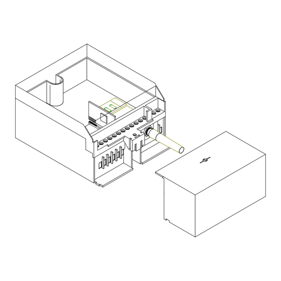
Page 32: Inserting The Interface Modules
UniMod GSM-4 Inserting the Interface Modules When inserting the interface modules their component side must be at the left side and wired according the picture. In the following sketch the com- ponents are at the left side. RS232 20mA active 20mA pas. RS485 M-Bus active M-Bus pas. -
Page 33: Terminal Block
UniMod GSM-4 Terminal Block Optional it is possible to activate the DTR input as control input (UE) for SMS. To enable this the jumper must be set from DTR to UE (see chap. 8.3) and the SMS functionality must be turned on using the UniMod- Set/MetcomTSet program. -
Page 34: Dimensions
UniMod GSM-4 Dimensions Wall-mounted housing according to DIN 43861-2 Subject to change without notice!
Need help?
Do you have a question about the UniMod GSM-4 and is the answer not in the manual?
Questions and answers