Table of Contents
Advertisement
Quick Links
Advertisement
Table of Contents

Related Manuals for LevelOne GEP-0950


Summary of Contents for LevelOne GEP-0950
- Page 1 GEP-0950 8 GE PoE-Plus + 1 GE SFP Web Smart Switch User Manual V1.0...
-
Page 2: Table Of Contents
..................... 4 NSTALLING THE WITCH 2-1-1. Hardware and Cable Installation ............... 4 2-1-2. Cabling Requirements ..................6 2-1-3. Configuring the Management Agent of GEP-0950 ..........9 2-1-4. IP Address Assignment ..................9 BASIC CONCEPT AND MANAGEMENT .............14 3-1. W ’... - Page 3 4-4-2. Factory Default ....................78 4-4-3. Software Upgrade ....................79 4-4-4. Configuration File Transfer ................80 Default Settings IP Address 192.168.1.1 Username admin Password admin...
-
Page 4: Electronic Emission Notices
Caution Circuit devices are sensitive to static electricity, which can damage their delicate electronics. Dry weather conditions or walking across a carpeted floor may cause you to acquire a static electrical charge. To protect your device, always: Touch the metal chassis of your computer to ground the static electrical charge before you pick up the circuit device. -
Page 5: Warning
Warning: Self-demolition on Product is strictly prohibited. Damage caused by self- demolition will be charged for repairing fees. Do not place product at outdoor or sandstorm. Before installation, please make sure input power supply and product specifications are compatible to each other. -
Page 7: Introduction
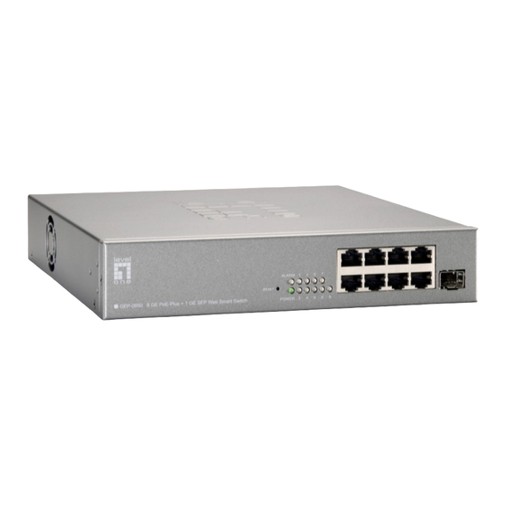
1. Introduction 1-1. Product Overview The LevelOne GEP-0950 is an intelligent Web Smart Switch, equipped with 8 x 10/100/1000Base-T PoE-Plus ports and 1 x 100/1000 Mbps dual speed SFP slot. It is IEEE802.3af/at compliant, provides power and data over a single Ethernet... - Page 8 Management • • Supports concisely the status of port and easily port configuration • Supports per port traffic monitoring counters • Supports 802.1Q VLAN • Supports user management and limits one user to login • Maximal packet length can be up to 9600 bytes for jumbo frame application •...
-
Page 9: Connectors And Leds
1-4. Connectors and LEDs 1-4-1. User Interfaces on the Front Panel (Button, LEDs and Plugs) There are 8 Gigabit Ethernet PoE ports and 1 SFP fiber ports for optional removable modules on the front panel of the switch. LED display area, locating on the left side of the panel, contains a Power LED, which indicates the power status and 8 ports working status of the switch. -
Page 10: Installation
2. Installation 2-1. Installing the Switch This section will give users a quick start for: Hardware and Cable Installation - Management Station Installation - Software booting and configuration 2-1-1. Hardware and Cable Installation At the beginning, please do first: Wear a grounding device to avoid the damage from electrostatic discharge ... - Page 11 4. Repeat the above steps, as needed, for each module to be installed into slot(s) 5. Have the power ON after the above procedures are done • TP Port and Cable Installation In the switch, TP port supports MDI/MDI-X auto-crossover, so both types of cable, straight-through (Cable pin-outs for RJ-45 jack 1, 2, 3, 6 to 1, 2, 3, 6 in 10/100M TP;...
-
Page 12: Cabling Requirements
2-1-2. Cabling Requirements To help ensure a successful installation and keep the network performance good, please take a care on the cabling requirement. Cables with worse specification will render the LAN to work poorly. 2-1-2-1. Cabling Requirements for TP Ports ... - Page 13 Case2a: Port-based VLAN 1. The same VLAN members could not be in different switches. 2. Every VLAN members could not access VLAN members each other. 3. The switch manager has to assign different names for each VLAN groups at one switch. Case 2b: Port-based VLAN Port-based VLAN Diagram 1.
- Page 14 Case3a: The same VLAN members can be at different switches with the same VID.
-
Page 15: Configuring The Management Agent Of Gep-0950
In the way of web, user is allowed to startup the switch management function. Users can use any one of them to monitor and configure the switch. 2-1-3-1. Configuring Management Agent of GEP-0950 through Ethernet Port There are two ways to configure and monitor the switch through the switch’s Ethernet port. - Page 16 identifier (address) and host identifier (address). The former indicates the network where the addressed host resides, and the latter indicates the individual host in the network which the address of host refers to. And the host identifier must be unique in the same LAN.
- Page 17 Class D is a class with first 4 MSB (Most significance bit) set to 1-1-1-0 and is used for IP Multicast. See also RFC 1112. Class E is a class with first 4 MSB set to 1-1-1-1 and is used for IP broadcast. According to IANA (Internet Assigned Numbers Authority), there are three specific IP address blocks reserved and able to be used for extending internal network.
- Page 18 Prefix Length No. of IP matched No. of Addressable IP 1024 1022 2048 2046 4096 4094 8192 8190 16384 16382 32768 32766 65536 65534 According to the scheme above, a subnet mask 255.255.255.0 will partition a network with the class C. It means there will have a maximum of 254 effective nodes existed in this sub-netted network and is considered a physical network in an autonomous network.
- Page 19 First, IP Address: as shown in the figure above, enter “192.168.1.1”, for instance. For sure, an IP address such as 192.168.1.x must be set on your PC. Second, Subnet Mask: as shown in the figure above, enter “255.255.255.0”. Any subnet mask such as 255.255.255.x is allowable in this case.
-
Page 20: Basic Concept And Management
3. Basic Concept and Management This chapter will tell you the basic concept of features to manage this switch and how they work. 3-1. What’s the Ethernet Ethernet originated and was implemented at Xerox in Palo Alto, CA in 1973 and was successfully commercialized by Digital Equipment Corporation (DEC), Intel and Xerox (DIX) in 1980. -
Page 21: Logical Link Control (Llc)
IEEE 802.2 LLC Data Link Layer IEEE802.3 CSMA/CD MAC IEEE 802.3 PLS Physical Layer ANSI X3T9.5 PMD IEEE 802.3 Fiber Coaxial/STP/UTP This above diagram shows the Ethernet architecture, LLC sub-layer and MAC sub-layer, which are responded to the Data Link layer, and transceivers, which are responded to the Physical layer in OSI model. - Page 22 SSAP, Control and Information. The DSAP address field identifies the one or more service access points, in which the I/G bit indicates it is individual or group address. If all bit of DSAP is 1s, it’s a global address. The SSAP address field identifies the specific services indicated by C/R bit (command or response).
-
Page 23: Media Access Control (Mac)
3-3. Media Access Control (MAC) 3-3-1. MAC Addressing Because LAN is composed of many nodes, for the data exchanged among these nodes, each node must have its own unique address to identify who should send the data or should receive the data. In OSI model, each layer provides its own mean to identify the unique address in some form, for example, IP address in network layer. - Page 24 Type/Length Data Pad bit if any 46-1500 Preamble (PRE) —The PRE is 7-byte long with alternating pattern of ones and zeros used to tell the receiving node that a frame is coming, and to synchronize the physical receiver with the incoming bit stream. The preamble pattern is: 10101010 10101010 10101010 10101010 10101010 10101010 10101010 Start-of-frame delimiter (SFD) —...
- Page 25 It is created by the sending MAC and recalculated by the receiving MAC to check if the packet is damaged or not. How does a MAC work? The MAC sub-layer has two primary jobs to do: 1. Receiving and transmitting data. When receiving data, it parses frame to detect error;...
- Page 26 Ethernet MAC transmits frames in half-duplex and full-duplex ways. In half- duplex operation mode, the MAC can either transmit or receive frame at a moment, but cannot do both jobs at the same time. As the transmission of a MAC frame with the half-duplex operation exists only in the same collision domain, the carrier signal needs to spend time to travel to reach the targeted device.
- Page 27 Parameter 10Base 100Base 1000Base value/LAN Max. collision 100 meters for UTP 100 meters for UTP domain DTE to 100 meters 412 meters for fiber 316 meters for fiber Max. collision domain with 2500 meters 205 meters 200 meters repeater Slot time 512 bit times 512 bit times 512 bit times...
-
Page 28: Flow Control
3-4. Flow Control Flow control is a mechanism to tell the source device stopping sending frame for a specified period of time designated by target device until the PAUSE time expires. This is accomplished by sending a PAUSE frame from target device to source device. - Page 29 Frame Reception In essence, the frame reception is the same in both operations of half duplex and full duplex, except that full-duplex operation uses two buffers to transmit and receive the frame independently. The receiving node always “listens” if there is traffic running over the medium when it is not receiving a frame.
- Page 30 the following table. Bits 15-13 User Priority 7-0, 0 is lowest priority CFI (Canonical Format Indicator) Bit 12 1: RIF field is present in the tag header 0: No RIF field is present VID (VLAN Identifier) 0x000: Null VID. No VID is present and only user Bits 11-0 priority is present.
-
Page 31: How Does A Switch Work
3-5. How does a switch work? The switch is a layer 2 Ethernet Switch equipped with 8 Gigabit Ethernet ports and 1 optional module which support Gigabit Ethernet or 100M Ethernet. Each port on it is an independent LAN segment and thus has 9 LAN segments and 9 collision domains, contrast to the traditional shared Ethernet HUB in which all ports share the same media and use the same collision domain and thus limit the bandwidth utilization. -
Page 32: Virtual Lan
3-6. Virtual LAN What is a VLAN? It is a subset of a LAN. Before we discuss VLAN, we must understand what LAN is. In general, a LAN is composed of different physical network segments bridged by switches or bridges which attach to end stations in the same broadcast domain. - Page 33 Now we apply VLAN technology to configure the system shown as the figure above. We can partition the users into the different logical networks which have their own broadcast domain. The traffic will not disturb among these logical networks. The users 1x (x denotes a ~ d) are members of VLAN 1. Any traffic within VLAN 1 does not flow to VLAN 2 and others.
- Page 34 Other VLAN technologies not mentioned above are MAC-based VLAN, IP- based VLAN and so on. Terminology Tagged Frame: A frame, carrying a tag field following the source MAC address, is four bytes long and contains VLAN protocol ID and tag control information composed of user priority, Canonical Format Indicator (CFI) and optional VLAN identifier (VID).
- Page 35 Port VLAN Identifier: VLAN identifier of a port. It also can be referred to as PVID. When an untagged frame or a priority-tagged frame is received, the frame will be inserted the PVID of that port in the VLAN tag field. The frame with VID assigned by a port is called PVID.
- Page 36 Independent VLAN Learning (IVL): It specifies the mode how to learn MAC address. For a specified VLAN, it will use an independent filtering database (FID) to learn or look up the membership information of the VLAN and decide where to go. Shared VLAN Learning (SVL): It specifies the mode how to learn MAC address.
- Page 37 Name Port Members Marketing Service 4,6,7 Sales Administration Next, assigns IP address to each VLAN. Usually, we use 10.x.x.x as internal IP block. Because there are total four VLANs in the network, we must assign 4 IP blocks to each of them. Name Network Address Marketing...
-
Page 38: Link Aggregation
3-7. Link Aggregation Basically, Link Aggregation is to aggregate the bandwidth of more than one port to an assigned logical link. This highly increases total bandwidth to the targeted device. There is more than one Link Aggregation technology in many vendors’ switch products already, which may cause the problem of interoperability. - Page 39 Terminology Link Aggregation: It is a method to have multiple physical links with the same media and speed bundled to be a logical link forming a Link Aggregation Group with a group ID. With the viewpoint of MAC client, each Link Aggregation Group is an independent link. There are three cases of link used in the network, which are switch to switch, switch to station and station to station.
-
Page 40: Operation Of Web-Based Management
10/100/1000Mbps TP Ports and Gigabit SFP Fiber ports on the switch via web user interfaces. GEP-0950 provides 8 fixed Gigabit Ethernet TP ports and 1 Gigabit SPF ports. With this facility, you can easily access and monitor the status like MIBs, port activity, and multicast traffic through any ports on the switch. -
Page 41: Web Management Home Overview
4-1. Web Management Home Overview After login, System Information would be displayed as below. This page lists default values and shows you the basic information of the switch, including “Switch Status”, “TP Port Status”, “Fiber Port Status”, “Aggregation”, “VLAN”, “Mirror”, “SNMP”, and “Maximum Packet Length”. -
Page 42: Configuration
4-2. Configuration Configuration includes the following functions: System Configuration, System Time, Ports Configuration, VLAN Mode Configuration, VLAN Group Configuration, VLAN Isolation, PoE Configuration, PoE State, PoE Auto Checking, PoE Scheduling, Aggregation, 802.1Z, IGMP Snooping, Mirroring, QOS, Loop detection, Broadcast storm Protection, SNMP. 4-2-1. - Page 43 Function name: System Configuration Function description: Show system description, firmware version, hardware version, MAC address, serial number, active IP address, active subnet mask, active gateway, DHCP server and Lease time left. Set device name, DHCP enable, fallback IP address, fallback subnet mask, fallback gateway, management VLAN, password and inactivity timeout.
- Page 44 Fallback IP Address: Users can configure the IP settings and fill in new values. Then, click <Apply> button to update. Default: 192.168.1.1 Fallback Subnet Mask: Subnet mask is made for the purpose to get more network address because any IP device in a network must own its IP address, composed of Network address and Host address, otherwise can’t communicate with other devices each other.
- Page 45 Default: admin Inactivity Timeout(secs): Set the auto-logout timer. The valid value is 0 ~ 60 in the unit of minute and a decimal point is not allowed. The value 0 means auto-logout timer is disabled. Default: 0...
-
Page 46: System Time
4-2-2. System Time Function name: System Time Function description: Allows users to sync system time with NTP Server. -
Page 47: Port Configuration
4-2-3. Port Configuration Function name: Port Configuration Function description: Port Configuration is applied for the settings of the ports on the switch. By this function, you can set or reset the values for Mode and Flow Control. Others you could set the power saving mode for switch power consumption. Port Configuration Parameter description: Enable Jumbo Frames:... - Page 48 the Enable / Disable Default: disable Link: Show link status of this port. Mode: Set the speed and duplex of the port. If the media is 1Gbps fiber, there are three modes to choose: Auto Speed, 1000 Full and Disable. If the media is TP, the Speed/Duplex is comprised of the combination of speed mode, 10/100/1000Mbps, and duplex mode, full duplex and half duplex.
-
Page 49: Vlan Mode Configuration
4-2-4. VLAN Mode Configuration GEP-0950 supports Port-based VLAN and Tag-based VLAN (802.1q). Its VLAN mode supports 9 active VLANs and the available VLAN ID range is from 1~4096. VLAN configuration is used to divide a LAN into smaller ones. With proper configuration, you can gain not only improved security and increased performance, but also save a lot of VLAN management effort. -
Page 50: Vlan Group Configuration
4-2-5. VLAN Group Configuration Function name: Tag-Based VLAN Configuration (Tag based VLAN mode) Function description: The VLAN membership configuration for the selected switch can be monitored and modified here. Up to 4096 VLANs are supported. This page allows for adding and deleting VLANs as well as adding and deleting port members of each VLAN. - Page 51 Parameter description: VID: VLAN identifier. Each tag-based VLAN group has a unique VID. It appears only in tag-based mode. Member: In modify function this is used to enable or disable if a port is a member of the new added VLAN, “Enable” means it is a member of the VLAN. Just tick the check box () beside the port x to enable it.
- Page 52 Function name: Port-Based VLAN Configuration (Port-based VLAN mode) Function description: It shows the information of VLAN Groups, and allows administrators to maintain them by modifying and deleting each VLAN group. User also can add a new VLAN group by inputting a new VLAN name and VLAN ID. If you are in port-based VLAN, it will just show the ID、Member of the existed port-based VLAN group.
- Page 53 Parameter description: ID (Group ID): When you want to edit a VLAN group, you must select the Group ID field. Then, you will enter Tag Base VLAN Group Setting or Port Base VLAN Group Setting page, which depends on your VLAN mode selection. Member: In modify function this is used to enable or disable if a port is a member of the new added VLAN, “Enable”...
-
Page 54: Vlan Port Isolation Configuration
4-2-6. VLAN Port Isolation Configuration Function name: Port Isolation Configuration Function description: Port Isolation provides for an apparatus and method to isolate ports on layer 2 switches on the same VLAN to restrict traffic flow. The apparatus comprises a switch having said plurality of ports, each port configured as a protected port or a non-protected port. -
Page 55: Poe
4-2-7. PoE Power Over Ethernet (PoE) technology allows IP telephones, wireless LAN access points, and other powered devices (PDs) to receive power and transfer data over existing LAN cabling. Function name: Power over Ethernet configuration Function description: In PoE Port Management function, user can configure the settings about PoE. The switch complies with IEEE 802.3at protocol and be capable of detecting automatically that whether the device linked to the port on the switch is PD (Powered Device) or not. - Page 56 The Delay time is using for set the time period for PD PoE enable time delay period. It is a solution to avoid rush current to cause shorter PD. The available time period is from 0 to 300 seconds and 0 means disable the function.
-
Page 57: Poe Status
4-2-8. PoE Status Function name: PoE State Function description: Display the information about the PoE status. Parameter description: Power Reservation: The watts are supplied by the PoE./ The maximal power that the switch can supply (Read Only). Port No: Port number. PD Class: Each PD is classified according to a class that defines the maximum power the PD will use. - Page 58 Port Status The Port Status shows the port's status. PoE turned OFF - PoE disabled : PoE is disabled by user. PoE turned OFF - Power budget exceeded - The total requested or used power by the PDs exceeds the maximum power the Power Supply can deliver, and port(s) with the lowest priority is/are powered down.
-
Page 59: Poe Auto Checking
4-2-9. PoE Auto Checking Function name: PoE Auto Checking Function description: The function is using for PD auto checking. It can allow user to control the PoE function by using the ping command, in order to turn on or off any PD which connect with port assign. -
Page 60: Poe Scheduling
4-2-10. PoE Scheduling Function name: PoE Scheduling Function description: This function allows the user to make a perfect schedule of PoE power supply. PoE Scheduling not only makes PoE management easier but also saves more energy. Parameter description: PoE On: Logical port which to configure power supply. - Page 61 Schedule mode: Enable / Disable PoE Scheduling. Port: Local port number. Scheduling: Click the desired day and time of when to activate PoE. is enable; blank is disable. Note: The PoE Scheduling will be disabled automatically when NTP sync time server failure occurs.
-
Page 62: Aggregation
4-2-11. Aggregation The Aggregation (Port Trunking) Configuration is used to configure the settings of Link Aggregation. You can bundle ports by same speed, MAC, and full duplex to be a single logical port, thus the logical port can aggregate the bandwidth of these ports. -
Page 63: Igmp Snooping
4-2-12. IGMP Snooping Function name: IGMP Snooping Configuration Function description: IGMP Snooping lets administrators configure a switch to constrain multicast traffic by listening to (IGMP). After finishing the Internet Group Management Protocol settings, please press <Apply> button to start up the function. Parameter description: IGMP Enabled: ) -
Page 64: Mirroring Configuration
4-2-13. Mirroring Configuration Function name: Mirror Configuration Function description: Mirror Configuration is provided to monitor the traffic in the network. This switch supports one-port mirror multi-ports. For example, we assume that Port A and Port B are Source Ports, and Port C is Mirror Port respectively, thus, the traffic passing through Port A and Port B will be copied to Port C for monitor purpose. -
Page 65: Qos(Quality Of Service) Configuration
4-2-14. QoS(Quality of Service) Configuration offers powerful QoS function. This function supports VLAN-tagged switch priority that can make precedence of 8 priorities, and DSCP(Differentiated Services Code Point) on Layer 3 of network framework. Function name: QoS Configuration Function description: While setting QoS function, please select QoS Mode in drop-down menu at first. - Page 66 Function name: DSCP QoS Mode Function description: In the late 1990s, the IETF redefined the meaning of the 8-bit SERVICE TYPE field to accommodate a set of differentiated services (DS). Under the differentiated services interpretation, the first six bits comprise a codepoint, which is sometimes abbreviated DSCP, and the last two bits are left unused.
-
Page 68: Loop Detection
4-2-15. Loop Detection Function name: Loop Detection Configuration Function description: The loop detection is used to detect the presence of traffic. When switch receives packet’s(looping detection frame) MAC address the same as oneself from port, show Loop detection happens. The port will be locked when it received the looping detection frames. - Page 69 When Port No is chosen and enable port' s Loop detection, the port can detect loop happens and port will be Locked. If Loop did not happen, port maintains Unlocked. Unlock port: When ticking the port, port locked will be opened and turned into unlocked.
-
Page 70: Broadcast Strom Protection
4-2-16. Broadcast Strom Protection Function name: Broadcast Strom Protection configuration Function description: When the broadcast packets received by the switch exceed the threshold configured, the port will be blocked for a period of time which can be set. After a configured time, the switch will detect whether the broadcast packets received on the port still exceed the threshold. - Page 71 Parameter description: Mode: Controls whether Broadcast Strom Protection is enabled (as a whole). Packet Per Second: It is a threshold. When the broadcast packet traffic in a second is higher than the threshold configured, the Broadcast Strom Protection enable. Unlock Time: The period (in seconds) for which a port will be kept disabled in the event of a loop is detected (and the port action is to shut down the port).
-
Page 72: Snmp
4-2-17. SNMP Any Network Management System (NMS) running the Simple Network Management Protocol (SNMP) can manage the Managed devices equipped with SNMP agent, provided that the Management Information Base (MIB) is installed correctly on the managed devices. It is a protocol used to govern the transfer of information between SNMP manager and agent and traverses the Object Identity (OID) of the management Information Base (MIB), described in the form of SMI syntax. - Page 73 Parameters description: SNMP enable: The term SNMP enable here is used for the activation or de-activation of SNMP. Default is “Disable”. Get/Set/Trap Community: Community name is used as password for authenticating if the requesting network management unit belongs to the same community group.
-
Page 74: Monitoring
4-3. Monitoring There are four functions contained in the monitoring function: Statistics Overview, Detailed, Statistics, IGMP Status and Ping 4-3-1. Statistics Overview Function name: Statistics Overview for all ports Function description: The section describes to the Port statistics information and provides overview of general traffic statistics for all switch ports. -
Page 75: Detailed Statistics
4-3-2. Detailed Statistics Function name: Detailed Statistics Function description: Display the detailed counting number of each port’s traffic. In the figure below, the window can show all counter information each port at one time. Parameter description: Rx Packets: The counting number of the packet received. RX Octets: Total received bytes. - Page 76 Rx Broad- and Multicast: Show the counting number of the received broadcast with multicast packet. Rx Error Packets: Show the counting number of the received error packets. Tx Packets: The counting number of the packet transmitted. TX Octets: Total transmitted bytes. Tx High Priority Packets: Number of Tx packets classified as high priority.
- Page 77 Number of 65 ~ 126-byte frames in good and bad packets transmitted. Tx 128-255 Bytes: Number of 127 ~ 255-byte frames in good and bad packets transmitted. Tx 256-511 Bytes: Number of 256 ~ 511-byte frames in good and bad packets transmitted. Tx 512-1023 Bytes: Number of 512 ~ 1023-byte frames in good and bad packets transmitted.
-
Page 78: Igmp Status
4-3-3. IGMP Status Function name: IGMP Status Function description: Display IGMP status. Parameter description: VLAN Id: Show VLAN Id for each multicast group. Querier: Show the group membership queries status. Queries transmitted: To count the group membership queries transmitted. Queries received: To count the group membership queries received. - Page 79 When a host receives a group membership query, it identifies the groups associated with the query and determines to which groups it belongs. The host then sets a timer, with a value less than the Max Response Time field in the query, for each group to which it belongs. It Calculate the number of times of IGMPV3 report.
-
Page 80: Ping Status
4-3-4. Ping Status Function name: Ping Status Function description: To set up target IP address for ping function and display ping status. Parameter description: Ping Parameters: Target IP address: Set up a Target IP address to ping. Count: Use drop-down menu to set number of echo requests to send. - Page 81 Status: Show the result of the ping status. Received replies: Show the received replies number of times. Request timeouts: Show the timeout of request. Average Response times (In ms): Show the average response time in milliseconds.
-
Page 82: Maintenance
4-4. Maintenance There are five functions contained in the maintenance function. Maintenance Warm Restart Factory Default Software Upgrade Configuration File Transfer Logout... -
Page 83: Warm Restart
4-4-1. Warm Restart Web Smart Switch offers many approaches to reboot your switch, such as: power up, hardware reset and software reset. You can press RESET button in the front panel of your switch to reset the device and to retrieve default settings. After upgrading software, you have to reboot the device to have new configuration take effect. - Page 84 4-4-2. Factory Default Function name: Factory Default Function description: Factory Default provides the function to retrieve default settings and replace current configuration. Except the IP address setting, all settings will be restored to the factory default values when “Factory Default” function is performed.
- Page 85 4-4-3. Software Upgrade Function name: Software Upgrade Function description: You can just click Browse button to retrieve the file you want in your system to upgrade your switch.
-
Page 86: Function Description
4-4-4. Configuration File Transfer Function name: Configuration File Transfer Function description: You can backup your switch’s configuration file into your computer folder in case accident happens. In addition, uploading backup configuration file into a new or a crashed switch can save much time and avoid mistakes.
Need help?
Do you have a question about the GEP-0950 and is the answer not in the manual?
Questions and answers