
Subscribe to Our Youtube Channel
Related Manuals for LevelOne GEP-1070


Summary of Contents for LevelOne GEP-1070
-
Page 1: User Manual
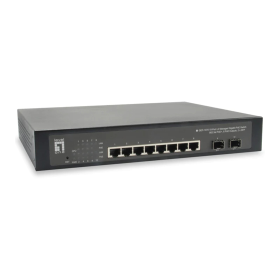
GEP-1070 L2 Managed Gigabit PoE Switch, 802.3at PoE+, 8 PoE Outputs, 2 x SFP User Manual V1.0 Digital Data Communications Asia Co., Ltd. http://www.level1.com... -
Page 2: About This Manual
About This Manual This manual gives specific information on how to operate and use the Purpose management functions of the Gigabit PoE Ethernet Switch. The Manual is intended for use by network administrators who are Audience responsible operating maintaining network equipment. - Page 3 for a Class A digital device, pursuant to Part 15 of the FCC Rules. These limits are designed to provide reasonable protection against harmful interference when equipment operated commercial environment. This equipment generates, uses, and can radiate radio frequency energy and, if not installed and used in accordance with the instruction manual, cause...
-
Page 4: Table Of Contents
Table of Content SECTION I GETTING STARTED .................. 9 1. INTRODUCTION ......................10 1.1. Key Features ....................10 1.2. Description of Software Features ..............12 1.3. Reset Button & LED Indicators ............... 16 1.4. System Defaults ..................... 17 2. INITIAL SWITCH CONFIGURATION ................20 SECTION II WEB CONFIGURATION ................. - Page 5 4.6. Aggregation ....................114 Static Trunks Configuration ................115 LACP Configuration ..................117 4.7. Loop Protection .................... 119 4.8. Spanning Tree ....................120 Bridge Settings ..................... 123 Multiple Spanning Trees Instance (MSTI) Mapping ........126 Multiple Spanning Tree Instance (MSTI) Priorities ........128 CIST Ports ....................
- Page 6 Configuring Telephony OUI ................183 4.18. Quality of Service (QoS) ................184 Configuring Port Classification ..............184 Configuring Port Policing ................186 Configuring Egress Port Scheduler ............... 187 Configuring Egress Port Shaper ..............190 Configuring Port Tag Remarking Mode............191 Configuring Port DSCP Translation and Rewriting ........
- Page 7 Switch Security ..................... 240 5.5. Link Aggregation Control Protocol (LACP) ............ 246 Displaying LACP System Status ..............246 Displaying LACP Port Status ................ 247 Displaying LACP Port Statistics ..............248 5.6. Loop Protection .................... 250 5.7. Spanning Tree ....................251 Displaying STP Bridge Status ...............
- Page 8 5.15. sFlow Statistics ..................... 284 6. DIAGNOSTICS ......................286 6.1. Pinging ......................286 6.2. ICMPv6 Pinging .................... 288 6.3. Running Cable Diagnostics ................290 7. MAINTENANCE ......................291 7.1. Restarting the Switch ..................291 7.2. Restoring Factory Defaults ................292 7.3.
-
Page 9: Getting Started
ECTION ETTING TARTED The Section I provides an overview of the GEP-1070 Layer-2 managed Gigabit PoE Switch, and introduces some basic concepts about switching network management. It also describes the basic settings required to access the management interfaces. This section includes these chapters: ◆... -
Page 10: Introduction
1. I NTRODUCTION The GEP-1070 is a Layer-2 managed Gigabit PoE Switch with 8-port UTP for Gigabit Ethernet cable plus 2-port SFP for Gigabit fiber link. It provides a broad range of management features for Layer 2 switching to deliver high levels of performance that are commensurate with Gigabit Ethernet networking. - Page 11 Feature Description Telnet, Web – user name/password, RADIUS, TACACS+ Authentication Web – HTTPS Telnet – SSH SNMP v1/2c - Community strings SNMP version 3 – MD5 or SHA password Port – IEEE 802.1X, MAC address filtering General Security Private VLANs Measures Port Authentication Port Security...
-
Page 12: Description Of Software Features
Feature Description Multicast Filtering Supports IGMP snooping and query, MLD snooping, and MulticastVLAN Registration 1.2. Description of Software Features CONFIGURATION BACKUP AND RESTORE You can save the current configuration settings to a file on the management station (using the web interface) or a TFTP server (using the console interface through Telnet), and later download this file to restore the switch configuration settings. - Page 13 Use the full-duplex mode on ports whenever possible to double the throughput of switch connections. Flow control should be enabled to control network traffic during periods of congestion and prevent the loss of packets when port buffer thresholds are exceeded. The switch supports flow control based on the IEEE 802.3x standard (incorporated in IEEE 802.3-2002).
- Page 14 IEEE 802.1D BRIDGE The switch supports IEEE 802.1D transparent bridging. The address table facilitates data switching by learning addresses, and then filtering or forwarding traffic based on this information. The address table supports up to 16K addresses. STORE-AND-FORWARD SWITCHING The switch copies each frame into its memory before forwarding them to another port. This ensures that all frames are a standard Ethernet size and have been verified for accuracy with the cyclic redundancy check (CRC).
- Page 15 ◆ Eliminate broadcast storms which severely degrade performance in a flat network. ◆ Simplify network management for node changes/moves by remotely configuring VLAN membership for any port, rather than having to manually change the network connection. ◆ Provide data security by restricting all traffic to the originating VLAN. ◆...
-
Page 16: Reset Button & Led Indicators
show the PoE class and wattage for each port. PoE Time Scheduling can be configured for ON/OFF in each port for 24-hour/7-days weekly basis. In addition, the keep-alive IP auto- checking can be enabled to ping the connected powered IP device. It can reboot and reset the power when the connected IP device fails to respond to the ping checking. -
Page 17: System Defaults
1.4. System Defaults The system defaults are provided in the configuration file “Config.xml.” To reset the switch defaults, this file should be set as the startup configuration file. The following table lists some of the basic system defaults. Table 3: System Defaults Function Parameter Default... - Page 18 Function Parameter Default Rate Limiting Input and output rate limits Disabled Port Trunking Static Trunks None LACP (all ports) Disabled Storm Protection Status Broadcast: Enabled (1 kpps) Multicast: disabled Unknown unicast: disabled Spanning Tree Status Enabled, RSTP Algorithm (Defaults: RSTP standard) Edge Ports Enabled Address Table...
- Page 19 Function Parameter Default Subnet Mask 255.255.255.0 Default Gateway 0.0.0.0 DHCP Client: Disabled Snooping:Disabled Proxy service: Disabled Multicast IGMP Snooping Snooping: Disabled Filtering Querier: Disabled MLD Snooping Disabled Multicast VLAN Registration Disabled System Log Status Disabled (console only) Messages Logged to Flash All levels Clock Synchronization Disabled...
-
Page 20: Initial Switch Configuration
2. I NITIAL WITCH ONFIGURATION This chapter includes information on installations of the switch and basic configuration procedures. To make use of the management features of your switch, you must first configure it with an IP address that is compatible with the network in which it is being installed. This should be done before you permanently install the switch in the network. -
Page 21: Web Configuration
SECTION II ONFIGURATION This section describes the basic switch features, along with a detailed description of how to configure each feature via a web browser. This section includes these chapters: ◆ "3. Using the Web Interface" on page 22 ◆ "4. Configuring the Switch" on page 34 ◆... -
Page 22: Using The Web Interface
3. U SING THE NTERFACE This switch provides an embedded HTTP web agent. Using a web browser you can configure the switch and view statistics to monitor network activity. The web agent can be accessed by any computer on the network using a standard web browser (Internet Explorer 5.0, Netscape 6.2, Mozilla Firefox 2.0.0.0, or more recent versions). -
Page 23: Panel Display
Table 4: Web Page Configuration Buttons Button Action Save Sets specified values to the system Reset Cancels specified values and restores current values prior to pressing “Save.” Logs out of the management interface Displays help for the selected page NOTE: To ensure proper screen refresh, be sure that Internet Explorer is configured so that the setting “Check for newer versions of stored pages”... - Page 24 Table 5: Main Menu Menu Description Page Configuration System Information Configures system contact, name and location Configures IPv4 and SNTP settings IPv6 Configures IPv6 and SNTP settings Enables NTP, and configures a list of NTP servers Configures the logging of messages to a remote logging process, specifies the remote log server, and limits the type of system log messages sent Power Reduction...
- Page 25 Menu Description Page Communities Configures community strings Users Configures SNMP v3 users on this switch Groups Configures SNMP v3 groups Views Configures SNMP v3 views Access Assigns security model, security level, and read / write views to SNMP groups Network Limit Control Configures port security limit controls, including secure address aging;...
- Page 26 Menu Description Page Static Table Adds static entries based on port, VLAN ID, and source MAC address and IP address in ARP request packets Configures RADIUS authentication server, RADIUS accounting server, and TACACS+ authentication server settings Aggregation Static Specifies ports to group into static trunks LACP Allows ports to dynamically join trunks Loop Protection...
- Page 27 Menu Description Page Configuration Port Group Configures multicast groups to be filtered on specified Filtering port LLDP Link Layer Discovery Protocol LLDP Configures global LLDP timing parameters, and port- specific TLV attributes LLDP-MED Configures LLDP-MED attributes, including device location, emergency call server, and network policy discovery Configures Power-over-Ethernet settings for each port Configuration...
- Page 28 Menu Description Page VoIP Traffic Configures global settings, including status, voice VLAN ID, VLAN aging time, and traffic priority; also configures port settings, including the way in which a port is added to the Voice VLAN, and blocking non- VoIP addresses Telephony OUI Maps the OUI in the source MAC address of ingress packets to the VoIP device manufacturer...
- Page 29 Menu Description Page Storm Control Sets limits for broadcast, multicast, and unknown unicast traffic Mirroring Sets source and target ports for mirroring UPnP Enables UPnP and defines timeout values Monitor System Displays basic system description, switch’s MAC Information address, system time, and software version CPU Load Displays graphic scale of CPU utilization Displays logged messages based on severity...
- Page 30 Menu Description Page Displays authentication statistics for the selected port – Port either 802.1X protocol the remote authentication server depending on the authentication method ACL Status Shows the status for different security modules which use ACL filtering, including ingress port, frame type, and forwarding action DHCP Dynamic Host Configuration Protocol...
- Page 31 Menu Description Page Spanning Tree Bridge Status Displays global bridge and port settings for STA Port Status Displays STA role, state, and uptime for each port Port Statistics Displays statistics for RSTP, STP and TCN protocol packets Multicast VLAN Registration Statistics Shows statistics for IGMP protocol messages used by Group Information...
- Page 32 Menu Description Page Displays status of all LLDP PoE neighbors, including power device type (PSE or PD), source of power, power priority, and maximum required power Displays Energy Efficient Ethernet information advertised through LLDP messages Port Statistics Displays statistics for all connected remote devices, and statistics for LLDP protocol packets crossing each port Displays the status for all PoE ports, including the PD class, requested power, allocated power, power and...
- Page 33 Menu Description Page Save Saves configuration settings to a file on the management station Upload Restores configuration settings from a file on the management station...
-
Page 34: Configuring The Switch
4. C ONFIGURING THE WITCH This chapter describes all of the basic configuration tasks for the switch management. 4.1. System System Information Configuration Use the System Information Configuration page to identify the system by configuring contact information, system name, location of the switch, and time zone offset. PATH Configuration / System / Information Figure 3: System Information Configuration... -
Page 35: Ip Configuration
WEB INTERFACE To configure System Information: 1. Click Configuration, System, Information. 2. Specify the contact information for the system administrator, as well as the name and location of the switch. Also indicate the local time zone by configuring the appropriate offset. - Page 36 Figure 4: IP Configuration PARAMETERS These parameters are displayed: IP Configuration ◆ DHCP Client – Specifies whether IP functionality is enabled via Dynamic Host Configuration Protocol (DHCP). If DHCP is enabled, IP will not function until a reply has been received from the server. Requests will be broadcasted periodically by the switch for an IP address.
-
Page 37: Ipv6 Configuration
IP DNS Proxy Configuration ◆ DNS Proxy – If enabled, the switch maintains a local database based on previous responses to DNS queries forwarded on behalf of attached clients. If the required information is not in the local database, the switch forwards the DNS query to a DNS server, stores the response in its local cache for future reference, and passes the response back to the client. - Page 38 Figure 5: IPv6 Configuration USAGE GUIDELINES ◆ All IPv6 addresses must be formatted according to RFC 2373 “IPv6 Addressing Architecture,” using 8 colon-separated 16-bit hexadecimal values. One double colon may be used in the address to indicate the appropriate number of zeros required to fill the undefined fields.
-
Page 39: Ntp Configuration
◆ Auto Configuration – Enables stateless autoconfiguration of IPv6 addresses on an interface and enables IPv6 functionality on the interface. The network portion of the address is based on prefixes received in IPv6 router advertisement messages, and the host portion is automatically generated using the modified EUI-64 form of the interface identifier;... -
Page 40: System Log Configuration
Figure 6: NTP Configuration PARAMETERS These parameters are displayed: ◆ Mode – Enables or disables NTP client requests. ◆ Server – Sets the IPv4 or IPv6 address for up to five time servers. The switch attempts to update the time from the first server, if this fails it attempts an update from the next server in the sequence. - Page 41 Figure 7: Configuring Settings for Remote Logging of Error Messages COMMAND USAGE When remote logging is enabled, system log messages are sent to the designated server. The syslog protocol is based on UDP and received on UDP port 514. UDP is a connectionless protocol and does not provide acknowledgments.
-
Page 42: Power Reduction
2. Enable remote logging, enter the IP address of the remote server, and specify the type of syslog messages to send. 3. Click Apply. 4.2. Power Reduction The switch provides power saving methods including controlling the intensity of LEDs, and powering down the circuitry for port queues when not in use. -
Page 43: Reducing Power For Eee
users) he might want to have full LED intensity during the maintenance period. Therefore it is possible to specify set the LEDs at full intensity for a specific period of time. Maintenance time is the number of seconds that the LEDs are set to full intensity after a port changes link state. - Page 44 Figure 9: Configuring EEE Power Reduction COMMAND USAGE ◆ EEE works by powering down circuits when there is no traffic. When a port gets data to be transmitted all relevant circuits are powered up. The time it takes to power up the circuits is call the wakeup time.
-
Page 45: Thermal Protection
WEB INTERFACE To configure the power reduction for idle queue circuits: 1. Click Configuration, Power Reduction, EEE. 2. Select the circuits which will use EEE. 3. If required, also specify urgent queues which will be powered up once data is queued and the default wakeup time has passed. -
Page 46: Ports
decrease power consumption. Port shut down can be prioritized based on assigned temperatures. PARAMETERS These parameters are displayed: Temperature settings for priority groups ◆ Priority – A priority assigned to a specific temperature. (Range: 0-3) ◆ Temperature – The temperature at which the ports with the corresponding priority will be turned off. - Page 47 Figure 11: Port Configuration PARAMETERS These parameters are displayed: ◆ Link – Indicates if the link is up or down. ◆ Speed – Sets the port speed and duplex mode using auto-negotiation or manual selection. The following options are supported: ■...
- Page 48 ◆ Flow Control – Flow control can eliminate frame loss by “blocking” traffic from end stations or segments connected directly to the switch when its buffers fill. When enabled, back pressure is used for half- duplex operation and IEEE 802.3-2005 (formally IEEE 802.3x) for full- duplex operation.
-
Page 49: Security
4.5. Security You can configure this switch to authenticate users logging into the system for management access or to control client access to the data ports. Management Access Security (Switch menu) – Management access to the switch can be controlled through local authentication of user names and passwords stored on the switch, or remote authentication of users via a RADIUS or TACACS+ server. - Page 50 COMMAND USAGE ◆ The default administrator name is “admin” without the password. ◆ The guest only has read access for most configuration parameters. However, the administrator has write access for all parameters governing the onboard agent. You should therefore assign a new administrator password as soon as possible, and store it in a safe place.
- Page 51 2. Click “Add new user.” 3. Enter the user name, password, and privilege level. 4. Click Save. Privilege Levels Configuration Use the Privilege Levels page to set the privilege level required to read or configure specific software modules or system settings. PATH Configuration \ Security \ Switch \ Privilege Levels Figure 13: Configuring Privilege Levels...
- Page 52 consists of a single module (e.g., LACP, RSTP or QoS), but a few groups contains more than one module. The following describes the groups which contain multiple modules or access to various system settings: ■ System: Contact, Name, Location, Timezone, Log ■...
- Page 53 controlled with a RADIUS or TACACS+ remote access authentication server. Note that the RADIUS servers used to authenticate client access for IEEE 802.1X port authentication are also configured on this page. Remote Authentication Dial-in User Service (RADIUS) and Terminal Access Controller Access Control System Plus (TACACS+) are logon authentication protocols that use software running on a central server to control access to RADIUS-aware or TACACS-aware devices on the network.
- Page 54 ◆ The switch supports the following authentication services: ■ Authorization of users that access the Telnet, SSH, the web, or console management interfaces on the switch. ■ Accounting for users that access the Telnet, SSH, the web, or console management interfaces on the switch.
- Page 55 1. Click Configuration, Security, Switch, Auth Method. 2. Configure the authentication method for management client types, and specify whether or not to fallback to local authentication if no remote authentication server is available. 3. Click Save. SSH Configuration Use the SSH Configuration page to configure access to the Secure Shell (SSH) management interface.
- Page 56 ◆ SSH service on this switch only supports password authentication. The password can be authenticated either locally or via a RADIUS or TACACS+ remote authentication server, as specified on the Auth Method menu (page 52). To use SSH with password authentication, the host public key must still be given to the client, either during initial connection or manually entered into the known host file.
- Page 57 USAGE GUIDELINES ◆ If you enable HTTPS, you must indicate this in the URL that you specify in your browser: https://device[:port-number] ◆ When you start HTTPS, the connection is established in this way: ■ The client authenticates the server using the server's digital certificate. ■...
- Page 58 PARAMETERS These parameters are displayed: ◆ Mode - Enables HTTPS service on the switch. (Default: Enabled) ◆ Automatic Redirect - Sets the HTTPS redirect mode operation. When enabled, management access to the HTTP web interface for the switch are automatically redirected to HTTPS.
- Page 59 PARAMETERS These parameters are displayed: ◆ Mode – Enables or disables filtering of management access based on configured IP addresses. (Default: Disabled) ◆ Start IP Address – The starting address of a range. ◆ End IP Address – The ending address of a range. ◆...
- Page 60 5. Mark the protocols to restrict based on the specified address range. 6. Click Save. SNMP Configuration Simple Network Management Protocol (SNMP) is a communication protocol designed specifically for managing devices on a network. Equipment commonly managed with SNMP includes switches, routers and host computers. SNMP is typically used to configure these devices for proper operation in a network environment, as well as to monitor them to evaluate performance or detect potential problems.
- Page 61 noAuth private default_ default_ default_ Community string only NoPriv rw_group view view noAuth user user user user Community string defined defined only NoPriv defined defined noAuth public default_r default_ none Community string NoPriv only o_group view noAuth private default_rw default_ default Community string NoPriv...
- Page 62 PARAMETERS These parameters are displayed: SNMP System Configuration ◆ Mode – Enables or disables SNMP service. (Default: Disabled) ◆ Version – Specifies the SNMP version to use. (Options: SNMP v1, SNMP v2c, SNMP v3; Default: SNMP v2c) ◆ Read Community – The community used for read-only access to the SNMP agent. (Range: 0-255 characters, ASCII characters 33-126 only;...
- Page 63 cleared. You will need to reconfigure all existing users. SNMP Trap Configuration ◆ Trap Mode - Enables or disables SNMP traps. (Default: Disabled) You should enable SNMP traps so that key events are reported by this switch to your management station. Traps indicating status changes can be issued by the switch to the specified trap manager by sending authentication failure messages and other trap messages.
- Page 64 enabled, the ID will be probed automatically. Otherwise, the ID specified in this field is used. (Range: 10-64 hex digits, excluding a string of all 0’s or all F’s) Note: The Trap Probe Security Engine ID must be disabled before an engine ID can be manually entered in this field.
- Page 65 Setting SNMPV3 Community Access Strings Use the SNMPv3 Community Configuration page to set community access strings. All community strings used to authorize access by SNMP v1 and v2c clients should be listed in the SNMPv3 Communities Configuration table. For security reasons, you should consider removing the default strings.
- Page 66 switch, along with the source address and address mask for each client. 4. Click Save. Configuring SNMPV3 Users Use the SNMPv3 User Configuration page to define a unique name and remote engine ID for each SNMPv3 user. Users must be configured with a specific security level, and the types of authentication and privacy protocols to use.
- Page 67 remote agent's SNMP engine ID before you can send proxy requests or informs to it. (See "Configuring SNMP System and Trap Settings" on page 60.) ◆ User Name - The name of user connecting to the SNMP agent. (Range: 1-32 characters, ASCII characters 33-126 only) ◆...
- Page 68 Figure 22: SNMPv3 Group Configuration PARAMETERS These parameters are displayed: ◆ Security Model - The user security model. (Options: SNMP v1, v2c, or the User-based Security Model – usm). ◆ Security Name - The name of a user connecting to the SNMP agent. (Range: 1-32 characters, ASCII characters 33-126 only) The options displayed for this parameter depend on the selected Security Model.
- Page 69 5. Enter a group name. Note that the views assigned to a group must be specified on the SNMP Accesses Configuration menu. 6. Click Save. Configuring SNMPV3 Views Use the SNMPv3 View Configuration page to define views which restrict user access to specified portions of the MIB tree.
- Page 70 OID string using an asterisk. (Length: 1-128) WEB INTERFACE To configure SNMPv3 views: 1. Click Configuration, Security, Switch, SNMP, Views. 2. Click “Add new view” to set up a new view. 3. Enter the view name, view type, and OID subtree. 4.
- Page 71 PARAMETERS These parameters are displayed: ◆ Group Name – The name of the SNMP group. (Range: 1-32 characters, ASCII characters 33-126 only) ◆ Security Model – The user security model. (Options: any, v1, v2c, or the User-based Security Model – usm; Default: any) ◆...
- Page 72 RMON Configuration RMON Statistics Use the RMON Statistics Configuration page for configurations. PATH Configuration \ Security \ Switch \ RMON \ Statistics Figure 25: RMON Statistics Configuration PARAMETERS These parameters are displayed: ◆ Delete – Check to delete the entry after the next save. ◆...
- Page 73 RMON History Use the RMON History Configuration page for configurations. PATH Configuration \ Security \ Switch \ RMON \ History Figure 26: RMON History Configuration PARAMETERS These parameters are displayed: ◆ Delete – Check to delete the entry after the next save. ◆...
- Page 74 RMON Alarm Use the RMON Alarm page for configurations. PATH Configuration \ Security \ Switch \ RMON \ Alarm Figure 27: RMON Alarm Configuration PARAMETERS These parameters are displayed: ◆ Delete – Check to delete the entry after the next save. ◆...
- Page 75 ■ OutUcastPkts: The number of uni-cast packets that request to transmit. ■ OutNUcastPkts: The number of broad-cast and multi-cast packets that request to transmit. ■ OutDiscards: The number of outbound packets that are discarded event the packets is normal. ■ OutErrors: The number of outbound packets that could not be transmitted because of errors.
- Page 76 RMON Event Use the RMON Event page for configurations. PATH Configuration \ Security \ Switch \ RMON \ Event Figure 28: RMON Event Configuration PARAMETERS These parameters are displayed: ◆ Delete – Check to delete the entry after the next save. ◆...
-
Page 77: Network Security
WEB INTERFACE To configure RMON Event table: 1. Click Configuration, Security, Switch, RMON, Event. 2. Click Add New Entry to create a new entry. The entry index key is ID. 3. Specify the ID, Data Source, Desc, Type, Community settings. 4. - Page 78 System Configuration ◆ Mode – Enables or disables Limit Control is globally on the switch. If globally disabled, other modules may still use the underlying functionality, but limit checks and corresponding actions are disabled. ◆ Aging Enabled – If enabled, secured MAC addresses are subject to aging as discussed under Aging Period.
- Page 79 ■ Disable and re-enable Limit Control on the port or the switch, ■ Click the Reopen button. ■ Trap & Shutdown: If Limit + 1 MAC addresses is seen on the port, both the “Trap” and the “Shutdown” actions described above will be taken. ◆...
- Page 80 authentication from any point within the network.
- Page 81 Figure 30: Using Port Security This switch uses the Extensible Authentication Protocol over LANs (EAPOL) to exchange authentication protocol messages with the client, and a remote RADIUS authentication server to verify user identity and access rights. These backend servers are configured on the AAA menu (see page 109).
- Page 82 ■ Each client that needs to be authenticated must have dot1x client software installed and properly configured. ■ When using 802.1X authentication, the RADIUS server and 802.1X client must support EAP. (The switch only supports EAPOL in order to pass the EAP packets from the server to the client.) ■...
- Page 83 USAGE GUIDELINES When 802.1X is enabled, you need to configure the parameters for the authentication process that runs between the client and the switch (i.e., authenticator), as well as the client identity lookup process that runs between the switch and authentication server. These parameters are described in this section.
- Page 84 MAC-based authentication. (Range: 10-1000000 seconds; Default: 10 seconds) If the RADIUS server denies a client access, or a RADIUS server request times out (according to the timeout specified on the AAA menu on page 109), the client is put on hold in the Unauthorized state.
- Page 85 Table 8: Dynamic QoS Profiles Profile Attribute Syntax Example DiffServ service-policy-in=policy-map-name service-policy-in=p1 Rate rate-limit-input=rate rate-limit-input=100 Limit (in units of Kbps) 802.1p switchport-priority-default=value switchport-priority- default=2 ■ Multiple profiles can be specified in the Filter-ID attribute by using a semicolon to separate each profile. For example, the attribute “service-policy-in=pp1;rate-limitinput=100”...
- Page 86 changes only take effect after all users have logged off the port. ◆ RADIUS-Assigned VLAN Enabled - RADIUS-assigned VLAN provides a means to centrally control the VLAN on which a successfully authenticated supplicant is placed on the switch. Incoming traffic will be classified to and switched on the RADIUS-assigned VLAN.
- Page 87 which is interpreted as a decimal string representing the VLAN ID. Leading '0's are discarded. The final value must be in the range 1-4095. The VLAN list can contain multiple VLAN identifiers in the format “1u,2t,3u” where “u” indicates an untagged VLAN and “t” a tagged VLAN. ◆...
- Page 88 ◆ Guest VLAN ID – This is the value that a port's Port VLAN ID is set to if a port is moved into the Guest VLAN. It is only changeable if the Guest VLAN option is globally enabled. (Range: 1-4095) ◆...
- Page 89 would cause all supplicants attached to the port to reply to requests sent from the switch. Instead, the switch uses the supplicant's MAC address, which is obtained from the first EAPOL Start or EAPOL Response Identity frame sent by the supplicant. An exception to this is when no supplicants are attached.
- Page 90 ■ Authenticated MAC addresses are stored as dynamic entries in the switch's secure MAC address table. Configured static MAC addresses are added to the secure address table when seen on a switch port. Static addresses are treated as authenticated without sending a request to a RADIUS server.
- Page 91 WEB INTERFACE To configure 802.1X Port Security: 1. Click Configuration, Security, Network, NAS. 2. Modify the required attributes. 3. Click Save. Access Control List (ACL) An Access Control List (ACL) is a sequential list of permit or deny conditions that apply to IP addresses, MAC addresses, or other more specific criteria.
- Page 92 PARAMETERS These parameters are displayed: ◆ Port – Port Identifier. ◆ Policy ID – An ACL policy configured on the ACL Entry (ACE) Configuration page. (Range: 1-8; Default: 1, which is undefined) ◆ Action – Permits or denies a frame based on whether it matches a rule defined in the assigned policy.
- Page 93 ◆ Logging - Enables logging of matching frames to the system log. (Default: Disabled) Open the System Log Information menu to view any entries stored in the system log for this entry. Related entries will be displayed under the “Info” or “All” logging levels. ◆...
- Page 94 PARAMETERS These parameters are displayed: ◆ Rate Limiter ID - Rate limiter identifier. (Range: 0-14; Default: 1) ◆ Rate - The threshold above which packets are dropped. (Options: 0-100 pps, or 0, 100, 2*100, 3*100, ... 1000000 kbps) Due to an ASIC limitation, the enforced rate limits are slightly less than the listed options. For example: 1 Kbps translates into an enforced threshold of 1002.1 pps.
- Page 95 Configuration \ Security \ Network \ ACL \ Access Control List Figure 34: Access Control List Configuration USAGE GUIDELINES ◆ Rules within an ACL are checked in the configured order, from top to bottom. A packe will be accepted as soon as it matches a permit rule, or dropped as soon as it matches a deny rule.
- Page 96 ◆ Rate Limiter – Shows if rate limiting will be enabled or disabled when matching frames are found. ◆ Port Copy – Shows the port to which matching frames are copied. ◆ Mirror – Mirrors matching frames from this port. (Default: Disabled) See "Configuring Port Mirroring"...
- Page 97 Ethernet Type Parameters ■ EtherType Filter – This option can only be used to filter Ethernet II formatted packets. (Options: Any, Specific (600-ffff hex); Default: Any) A detailed listing of Ethernet protocol types can be found in RFC 1060. A few of the more common types include 0800 (IP), 0806 (ARP), 8137 (IPX).
- Page 98 Ethernet (0x06) and the (PLN) is equal to IPv4 (0x04) must not match this entry, 1 - ARP/RARP frames where the HLN is equal to Ethernet (0x06) and the (PLN) is equal to IPv4 (0x04) must match this entry; Default: Any) ■...
- Page 99 Any) ■ TCP SYN – Specifies the TCP “Synchronize sequence numbers” (SYN) value for this rule. (Options: Any - any value is allowed, 0 - TCP frames where the SYN field is set must not match this entry, 1 -TCP frames where the SYN field is set must match this entry; Default: Any) ■...
- Page 100 ◆ Action – Permits or denies a frame based on whether it matches an ACL rule. (Default: Permit) ◆ Rate Limiter – Specifies a rate limiter (page 91) to apply to the port. (Range: 1-16; Default: Disabled) ◆ Port Copy – Defines a port to which matching frames are copied. (Range: 1-10; Default: Disabled) ◆...
- Page 101 DHCP Use the DHCP Snooping Configuration page to filter IP traffic on insecure ports for which the source address cannot be identified via DHCP snooping. The addresses assigned to DHCP clients on insecure ports can be carefully controlled using the dynamic bindings registered with DHCP Snooping (or using the static bindings configured with IP Source Guard).
- Page 102 ◆ When DHCP snooping is enabled, DHCP messages entering an untrusted interface are filtered based upon dynamic entries learned via DHCP snooping. ◆ Filtering rules are implemented as follows: ■ If the global DHCP snooping is disabled, all DHCP packets are forwarded. ■...
- Page 103 WEB INTERFACE To configure DHCP Snooping: 1. Click Configuration, Security, Network, DHCP, Snooping. 2. Set the status for the global DHCP snooping process, and set any ports within the local network or firewall to trusted. 3. Click Apply Configuring DHCP Relay and Option 82 Information Use the DHCP Relay Configuration page to configure DHCP relay service for attached host devices.
- Page 104 Figure 36: DHCP Relay Configuration PARAMETERS These parameters are displayed: ◆ Relay Mode – Enables or disables the DHCP relay function. (Default: Disabled) ◆ Relay Server – IP address of DHCP server to be used by the switch's DHCP relay agent. ◆...
- Page 105 manually configured entries in the IP Source Guard table, or dynamic entries in the DHCP Snooping table when enabled (see "Configuring DHCP Snooping"). IP source guard can be used to prevent traffic attacks caused when a host tries to use the IP address of a neighbor to access the network.
- Page 106 binding table. If no matching entry is found, the packet will be dropped. ◆ Filtering rules are implemented as follows: ■ If DHCP snooping is disabled, IP source guard will check the VLAN ID, source IP address, and port number. If a matching entry is found in the binding table and the entry type is static IP source guard binding, the packet will be forwarded.
- Page 107 Configuring Static Bindings for IP Source Guard Use the Static IP Source Guard Table to bind a static address to a port. Table entries include a port identifier, VLAN identifier, IP address, and subnet mask. All static entries are configured with an infinite lease time. PATH Configuration \ Security \ Network \ IP Source Guard \ Static Table Figure 38: Configuring Static IP Source Guard Table...
- Page 108 ◆ Port – The port to which a static entry is bound. ◆ VLAN ID – The VLAN ID of a configured VLAN (Range: 1-4095). ◆ IP Address – Allowed Source IP address. A valid unicast IP address, including class types A, B or C.
- Page 109 has been enabled. ■ When ARP Inspection is enabled globally, all ARP request and reply packets on inspection-enabled ports are redirected to the CPU and their switching behavior handled by the ARP Inspection engine. ■ If ARP Inspection is disabled globally, then it becomes inactive for all ports, including those where inspection is enabled.
- Page 110 Figure 39: Configuring Global and Port Settings for ARP Inspection PARAMETERS These parameters are displayed: ARP Inspection Configuration ◆ Mode – Enables Dynamic ARP Inspection globally. (Default: Disabled) Port Mode Configuration ◆ Port – Port identifier ◆ Mode – Enables Dynamic ARP Inspection on a given port. Only when both Global Mode and Port Mode on a given port are enabled, will ARP Inspection be enabled on a given port.
- Page 111 port identifier, VLAN identifier, source MAC address in ARP request packets, and source IP address in ARP request packets. ARP Inspection uses the DHCP snooping bindings database for the list of valid IP-to-MAC address bindings. Static ARP entries take precedence over entries in the DHCP snooping bindings database.
-
Page 112: Authentication Servers (Aaa)
Authentication Servers (AAA) Use the Authentication Server Configuration page to control management access based on a list of user names and passwords configured on a RADIUS or TACACS+ remote access authentication server, and to authenticate client access for IEEE 802.1X port authentication. Note: This guide assumes that RADIUS and TACACS+ servers have already been configured to support AAA. - Page 113 Figure 41: Authentication Configuration PARAMETERS These parameters are displayed: Common Server Configuration ◆ Timeout – The time the switch waits for a reply from an authentication server before it resends the request. (Range: 3-3600 seconds; Default: 15 seconds) ◆ Dead Time – The time after which the switch considers an authentication server to be dead if it does not reply.
-
Page 114: Aggregation
29 characters) To set an empty secret, use two quotes (“”). To use spaces in the secret, enquote the secret. Quotes in the secret are not allowed. WEB INTERFACE To configure authentication for management access in the web interface: 1. Click Configuration, Security, AAA. 2. -
Page 115: Static Trunks Configuration
◆ The ports at both ends of a connection must be configured as trunk ports. ◆ When configuring static trunks on switches of different types, they must be compatible with the Cisco EtherChannel standard. ◆ The ports at both ends of a trunk must be configured in an identical manner, including communication mode (i.e., speed, duplex mode and flow control), VLAN assignments, and CoS settings. - Page 116 removing a static trunk via the configuration interface. ◆ When incoming data frames are forwarded through the switch to a trunk, the switch must determine to which port link in the trunk an outgoing frame should be sent. To maintain the frame sequence of various traffic flows between devices in the network, the switch also needs to ensure that frames in each “conversation”...
-
Page 117: Lacp Configuration
web browsing. However, it can be used effectively in combination with the IP Address option. (One of the defaults.) Aggregation Group Configuration ◆ Group ID – Trunk identifier. (Range: 1-5) ◆ Port Members – Port identifier. WEB INTERFACE To configure a static trunk: 1. - Page 118 ◆ If the target switch has also enabled LACP on the connected ports, the trunk will be activated automatically. ◆ A trunk formed with another switch using LACP will automatically be assigned the next available trunk ID. ◆ If more than eight ports attached to the same target switch have LACP enabled, the additional ports will be placed in standby mode, and will only be enabled if one of the active links fails.
-
Page 119: Loop Protection
3. Specify the LACP Admin Key to restrict a port to a specific LAG. 4. Set at least one of the ports in each LAG to Active initiation mode, either at the near end or far end of the trunk. 5. -
Page 120: Spanning Tree
restart). Port Configurations: ◆ Port – The switch port number of the port.. ◆ Enable – Controls whether loop protection is enabled on this switch port. ◆ Action – Configures the action performed when a loop is detected on a port. Valid values are Shutdown Port, Shutdown Port and Log or Log Only. - Page 121 and designated ports, and disables all other ports. Network packets are therefore only forwarded between root ports and designated ports, eliminating any possible network loops. Figure 45: STP Root Ports and Designated Ports Once a stable network topology has been established, all bridges listen for Hello BPDUs (Bridge Protocol Data Units) transmitted from the Root Bridge.
- Page 122 An MST Region consists of a group of interconnected bridges that have the same MST Configuration Identifiers (including the Region Name, Revision Level and Configuration Digest – see "Configuring Multiple Spanning Trees" on page 123). An MST Region may contain multiple MSTP Instances. An Internal Spanning Tree (IST) is used to connect all the MSTP switches within an MST region.
-
Page 123: Bridge Settings
Bridge Settings Using the onboard web agent, you can define system parameters, manage and control the switch, and all its ports, or monitor network conditions. The following table briefly describes the selections available from this program. Use the STP Bridge Settings page to configure settings for STA which apply globally to the switch. - Page 124 after the migration delay expires, RSTP restarts the migration delay timer and begins using RSTP BPDUs on that port. ◆ Multiple Spanning Tree Protocol MSTP generates a unique spanning tree for each instance. This provides multiple pathways across the network, thereby balancing the traffic load, preventing wide-scale disruption when a bridge node in a single instance fails, and allowing for faster convergence of a new topology for the failed instance.
- Page 125 ■ Options: 0, 16, 32, 48, 64, 80, 96, 112, 128, 144, 160, 176, 192, 208, 224, 240 ◆ Forward Delay – The maximum time (in seconds) this device will wait before changing states (i.e., discarding to learning to forwarding). This delay is required because every device must receive information about topology changes before it starts to forward frames.
-
Page 126: Multiple Spanning Trees Instance (Msti) Mapping
such as a connection to an unauthorized device. The BPDU guard feature provides a secure response to invalid configurations because an administrator must manually enable the port. (Default: Disabled) ◆ Port Error Recovery – Controls whether a port in the error-disabled state will be automatically enabled after a certain time. - Page 127 COMMAND USAGE MSTP generates a unique spanning tree for each instance. This provides multiple pathways across the network, thereby balancing the traffic load, preventing wide- scale disruption when a bridge node in a single instance fails, and allowing for faster convergence of a new topology for the failed instance.
-
Page 128: Multiple Spanning Tree Instance (Msti) Priorities
These parameters are displayed: Configuration Identification ◆ Configuration Name2 – The name for this MSTI. (Maximum length: 32 characters; Default: switch’s MAC address) ◆ Configuration Revision2 – The revision for this MSTI. (Range: 0-65535; Default: 0) ––––––––––––––––––––––––––––––––––––––––––––––––– 2. The MST name and revision number are both required to uniquely identify an MST region. –––––––––––––––––––––––––––––––––––––––––––––––––... -
Page 129: Cist Ports
PARAMETERS These parameters are displayed: ◆ MSTI – Instance identifier to configure. (Range: CIST, MIST1-7) ◆ Priority – The priority of a spanning tree instance. (Range: 0-240 in steps of 16; Options: 0, 16, 32, 48, 64, 80, 96, 112, 128, 144, 160, 176, 192, 208, 224, 240; Default: 128) Bridge priority is used in selecting the root device, root port, and designated port. - Page 130 “ports” in this section means “interfaces,” which includes both ports and trunks.) PATH Configuration \ Spanning Tree \ CIST Ports Figure 51: STP CIST Port Configuration PARAMETERS These parameters are displayed: ◆ Port – Port identifier. This field is not applicable to static trunks or dynamic trunks created through LACP. Also, note that only one set of interface configuration settings can be applied to all trunks.
- Page 131 each port, and configures the path cost according to the values shown below. Table 10: Recommended STA Path Cost Range Port Type IEEE 802.1D-1998 IEEE 802.1w-2001 Ethernet 50-600 200,000-20,000,000 Fast Ethernet 10-60 20,000-2,000,000 Gigabit Ethernet 3-10 2,000-200,000 Table 11: Recommended STA Path Costs Port Type Link Type IEEE 802.1D-1998...
- Page 132 cost for all ports on a switch are the same, the port with the highest priority (i.e., lowest value) will be configured as an active link in the Spanning Tree. This makes a port with higher priority less likely to be blocked if the Spanning Tree Algorithm is detecting network loops.
-
Page 133: Msti Ports
◆ Point-to-Point – The link type attached to an interface can be set to automatically detect the link type, or manually configured as point-to- point or shared medium. Transition to the forwarding state is faster for point-to-point links than for shared media. These options are described below: ■... -
Page 134: Multicast Vlan Registration (Mvr)
PARAMETERS These parameters are displayed: ◆ Port – Port identifier. This field is not applicable to static trunks or dynamic trunks created through LACP. Also, note that only one set of interface configuration settings can be applied to all trunks. ◆... - Page 135 provider, and to configure each interface that participates in the MVR protocol as a source port or receiver port. Multicast VLAN Registration (MVR) is a protocol that controls access to a single network- wide VLAN most commonly used for transmitting multicast traffic (such as television channels or video-on-demand) across a service provider’s network.
- Page 136 Figure 53: MVR Concept PATH Configuration \ MVR Figure 54: MVR Configuration COMMAND USAGE ◆General Configuration Guidelines for MVR: 1. Enable MVR globally on the switch, and select the MVR VLAN.
- Page 137 2. Set the interfaces that will join the MVR as source ports or receiver ports. 3. If you are sure that only one subscriber attached to an interface is receiving multicast services, you can enable the immediate leave function. ◆ Although MVR operates on the underlying mechanism of IGMP snooping, the two features operate independently of each other.
-
Page 138: Ipmc Configurations
Just remember that only IGMP version 2 or 3 hosts can issue multicast leave messages. If a version 1 host is receiving multicast traffic, the switch can only remove the interface from the multicast stream after the host responds to a periodic request for a membership report. WEB INTERFACE To configure global and interface settings for MVR: 1. - Page 139 multicast packets will only be forwarded to those ports containing multicast group hosts or multicast routers/switches, instead of flooding traffic to all ports in the subnet (VLAN). Basic Configuration for IGMP Snooping Use the IGMP Snooping Configuration page to configure global and port- related settings which control the forwarding of multicast traffic.
- Page 140 ◆ Snooping Enabled – When enabled, the switch will monitor network traffic to determine which hosts want to receive multicast traffic. (Default: Enabled) This switch can passively snoop on IGMP Query and Report packets transferred between IP multicast routers/switches and IP multicast host groups to identify the IP multicast group members.
- Page 141 natively to the upstream multicast routers. Port Related Configuration ◆ Port – Port identifier. ◆ Router Port – Sets a port to function as a router port, which leads towards a Layer 3 multicast device or IGMP querier. (Default: Disabled) If IGMP snooping cannot locate the IGMP querier, you can manually designate a port which is connected to a known IGMP querier (i.e., a multicast router/switch).
- Page 142 To configure global and port-related settings for IGMP Snooping: 1. Click Configuration, IPMC, IGMP Snooping, Basic Configuration. 2. Adjust the IGMP settings as required. 3. Click Save. VLAN Configuration for IGMP Snooping Use the IGMP Snooping VLAN Configuration page to configure IGMP snooping and query for a VLAN interface PATH Configuration \ IPMC \ IGMP Snooping \ VLAN Configuration...
- Page 143 multicast traffic. If there is more than one router/ switch on the LAN performing IP multicasting, one of these devices is elected “querier” and assumes the role of querying the LAN for group members. It then propagates the service requests on to any upstream multicast switch/router to ensure that it will continue to receive the multicast service.
- Page 144 WEB INTERFACE To configure VLAN settings for IGMP snooping and query: 1. Click Configuration, IPMC, IGMP Snooping, VLAN Configuration. 2. Adjust the IGMP settings as required. 3. Click Save. Port Group Filtering for IGMP Snooping Use the IGMP Snooping Port Group Filtering Configuration page to filter specific multicast traffic.
-
Page 145: Mld Snooping
To configure IGMP Snooping Port Group Filtering: 1. Click Configuration, IGMP Snooping, Port Group Filtering. 2. Click Add New Filtering Group to display a new entry in the table. 3. Select the port to which the filter will be applied. 4. - Page 146 Figure 58: Configuring Global and Port-related Settings for MLD Snooping PARAMETERS These parameters are displayed: Global Configuration ◆ Snooping Enabled – When enabled, the switch will monitor network traffic to determine which hosts want to receive multicast traffic. (Default: Disabled) This switch can passively snoop on MLD Listener Query and Report packets transferred between IP multicast routers/switches and IP multicast host groups to identify the IP multicast group members.
- Page 147 the last member query timer for that port. When the conditions in the preceding item all apply, except that the receiving port is a router port, then the switch will not send a GS-query, but will immediately start the last member query timer for that port.
- Page 148 attached to it. Fast Leave can improve bandwidth usage for a network which frequently experiences many MLD host add and leave requests. ◆ Throttling – Limits the number of multicast groups to which a port can belong. (Range: 1- 10; Default: unlimited) MLD throttling sets a maximum number of multicast groups that a port can join at the same time.
- Page 149 ◆ Snooping Enabled – When enabled, the switch will monitor network traffic on the indicated VLAN interface to determine which hosts want to receive multicast traffic. (Default: Disabled) When MLD snooping is enabled globally, the per VLAN interface settings for MLD snooping take precedence.
- Page 150 wait for a response to a group-specific or groupand-source-specific query message. The overall time to wait for a response (Last Member Query Time) is the value assigned to LLQI, multiplied by the Last Member Query Count (which is fixed at 2). (Range: 1-31744 tenths of a second in multiples of 10;...
- Page 151 Figure 60: MLD Snooping Port Group Filtering Configuration PARAMETERS These parameters are displayed: ◆ Port – Port identifier. ◆ Filtering Groups – Multicast groups that are denied on a port. When filter groups are defined, MLD listener reports received on a port are checked against the these groups. If a requested multicast group is denied, the MLD report is dropped.
-
Page 152: Link Layer Discovery Protocol (Lldp)
4.11. Link Layer Discovery Protocol (LLDP) Link Layer Discovery Protocol (LLDP) is used to discover basic information about neighboring devices on the local broadcast domain. LLDP is a Layer 2 protocol that uses periodic broadcasts to advertise information about the sending device. Advertised information is represented in Type Length Value (TLV) format according to the IEEE 802.1AB standard, and can include details such as device identification, capabilities and configuration settings. - Page 153 5-32768 seconds; Default: 30 seconds) This attribute must comply with the following rule: (Transmission Interval * Transmission Hold Time) ≤ 65536, and Transmission Interval ≥ (4 * Transmission Delay) ◆ Tx Hold – Configures the time-to-live (TTL) value sent in LLDP advertisements as shown in the formula below.
- Page 154 ■ Both the CDP and LLDP support “system capabilities,” but the CDP capabilities cover capabilities that are not part of LLDP. These capabilities are shown as “others” in the LLDP neighbors table. If all ports have CDP awareness disabled, the switch forwards CDP frames received from neighbor devices.
-
Page 155: Lldp-Med Configuration
5. Specify the information to include in the TLV field of advertised messages. 6. Click Save. LLDP-MED Configuration Use the LLDP-MED Configuration page to set the device information which is advertised for end-point devices. LLDP-MED (Link Layer Discovery Protocol - Media Endpoint Discovery) is an extension of LLDP intended for managing endpoint devices such as Voice over IP phones and network switches. - Page 156 Identification Discovery of endpoints is a critically important aspect of VoIP systems in general.In addition, it is best to advertise only those pieces of information which are specifically relevant to particular endpoint types (for example only advertise the voice network policy to permitted voice-capable devices), both in order to conserve the limited LLDPU space and to reduce security and system integrity issues that can come with inappropriate knowledge of the network policy.
- Page 157 ■ NAD83/NAVD88: North American Datum 1983, CRS Code 4269, Prime Meridian Name: Greenwich; The associated vertical datum is the North American Vertical Datum of 1988 (NAVD88). This datum pair is to be used when referencing locations on land, not near tidal water (which would use Datum = NAD83/MLLW).
- Page 158 defined by TIA or NENA. ELIN identifier data format is defined to carry the ELIN identifier as used during emergency call setup to a traditional CAMA or ISDN trunk-based PSAP. This format consists of a numerical digit string, corresponding to the ELIN to be used for emergency calling. ◆...
- Page 159 VLAN for ease of deployment and enhanced security by isolation from data applications. ■ Voice Signaling (conditional) – For use in network topologies that require a different policy for the voice signaling than for the voice media. This application type should not be advertised if all the same network policies apply as those advertised in the Voice application policy.
-
Page 160: Power Over Ethernet (Poe)
■ DSCP – DSCP value used to provide Diffserv node behavior for the specified application type as defined in IETF RFC 2474. DSCP may contain one of 64 code point values (0 - 63). A value of 0 represents use of the default DSCP value as defined in RFC 2475. ◆... -
Page 161: Poe Configuration
exchanges information with the PD such as duty-cycle, peak and average power needs. ◆ All the RJ-45 ports support both the IEEE 802.3af and IEEE 802.3at standards. The total PoE power delivered by all ports cannot exceed the maximum power budget. ◆... - Page 162 These parameters are displayed: ◆ Reserved Power determined by – There are three modes for configuring how the ports or attached Powered Devices (PD) may reserve power: ■ Class – Each port automatically determines how much power to reserve according to the class to which the connected PD belongs, and reserves power accordingly.
-
Page 163: Poe Scheduling
◆ Maximum Power -The maximum power that can be delivered to a remote device. (Range: 0-34.2 Watts depending on the PoE mode) WEB INTERFACE To configure global and port-specific PoE settings: 1. Click Configuration, PoE, configuration. 2. Set the global PoE parameters, including the method used to determinereserved port power, the method by which port power is shut down, and the switch’s overall power budget. -
Page 164: Poe Auto Checking
PARAMETERS These parameters are displayed: ◆ Setting Action Port – This is the logical port number for setting time scheduling. ◆ Mode – This is to enable / disable the PoE scheduling for the selected port. ◆ Hour – The Hour represents the hourly period of the weekly table on 24Hour/7Day basis. PoE OFF in this hourly period. - Page 165 retries, the switch will issue a PoE reboot to restart the PoE IP device. PATH Configuration \ PoE \ Autochecking Figure 65: Configuring PoE Autochecking PARAMETERS These parameters are displayed: ◆ Port – This is the logical port number for setting autochecking. ◆...
-
Page 166: Mac Address Table
WEB INTERFACE To configure the port-specific PoE IP checking: 1. Click Configuration, PoE, Autochecking. 2. Select the port for enabling PoE IP checking. 3. Enter the corresponding IP address, Interval Number, Failure Action, Retry Number, and the desired Reboot Time. 4. - Page 167 Aging Configuration ◆ Disable Automatic Aging – Disables the automatic aging of dynamic entries. (Address aging is enabled by default.) ◆ Aging Time – The time after which a learned entry is discarded. (Range: 10-1000000 seconds; Default: 300 seconds) MAC Table Learning ◆...
-
Page 169: Ieee 802.1Q Vlans
4.14. IEEE 802.1Q VLANs In large networks, routers are used to isolate broadcast traffic for each subnet into separate domains. This switch provides a similar service at Layer 2 by using VLANs to organize any group of network nodes into separate broadcast domains. VLANs confine broadcast traffic to the originating group, and can eliminate broadcast storms in large networks. -
Page 170: Vlan Membership
VLAN Membership Use the VLAN Membership Configuration page to enable VLANs for this switch by assigning each port to the VLAN group(s) in which it will participate. PATH Configuration \ VLANs \ VLAN Membership Figure 67: VLAN Membership Configuration PARAMETERS These parameters are displayed: ◆... - Page 171 including processing Queue-in-Queue frames with embedded tags, enabling ingress filtering, setting the accepted frame types, and configuring the default VLAN identifier (PVID). PATH Configuration \ VLANs \ Ports Figure 68: VLAN Port Configuration PARAMETERS These parameters are displayed: ◆ Ethertype for Custom S-ports – When Port Type is set to S-customport, the EtherType (also called the Tag Protocol Identifier or TPID) of all frames received on the port is changed to the specified value.
- Page 172 nor change any components of the tag other than the EtherType field. ■ S-custom-port – For custom service ports, the EtherType of all received frames is changed to value set in the Ethertype for Custom S-ports field to indicate that double- tagged frames are being forwarded across the switch.
-
Page 173: Private Vlans
WEB INTERFACE To configure attributes for VLAN port members: 1. Click Configuration, VLANs, Ports. 2. Configure in the required settings for each interface. 3. Click Save. 4.15. Private VLANs PVLAN Membership Use the Private VLAN Membership Configuration page to assign port members to private VLANs. -
Page 174: Port Isolation
PARAMETERS These parameters are displayed: ◆ PVLAN ID – Private VLAN identifier. (Range: 1-4095) By default, all ports are configured as members of VLAN 1 and PVLAN 1. Because all of these ports are members of 802.1Q VLAN 1, isolation cannot be enforced between the members of PVLAN 1. -
Page 175: Vcl Configuration
Figure 70: Port Isolation Configuration PARAMETERS These parameters are displayed: ◆ Port Number – Port identifier. WEB INTERFACE To configure isolated ports: 1. Click Configuration, Private VLANs, Port Isolation. 2. Mark the ports which are to be isolated from each other. 3. -
Page 176: Protocol-Based Vlan
COMMAND USAGE ◆ Source MAC addresses can be mapped to only one VLAN ID. ◆ Configured MAC addresses cannot be broadcast or multicast addresses. ◆ When MAC-based and protocol-based VLANs are both enabled, priority is applied in this sequence, and then port-based VLANs last. PARAMETERS These parameters are displayed: ◆... - Page 177 common VLAN. This may require non-standard devices to pass traffic between different VLANs in order to encompass all the devices participating in a specific protocol. This kind of configuration deprives users of the basic benefits of VLANs, including security and easy accessibility.
- Page 178 PARAMETERS These parameters are displayed: ◆ Frame Type – Choose Ethernet, LLC (Logical Link Control), or SNAP (SubNetwork Access Protocol - RFC 1042) as the frame type used by this protocol. ◆ Value – Values which define the specific protocol type. The fields displayed depend on the selected frame type: Ethernet –...
- Page 179 Groups to VLAN Use the Group Name to VLAN Mapping Table to map a protocol group to a VLAN for each interface that will participate in the group. PATH Configuration \ VCL \ Protocol-based VLAN \ Group to VLAN Figure 73: Assigning Ports to Protocol VLANs COMMAND USAGE ◆...
-
Page 180: Voice Vlan
(a-z or A-Z) or integers (0-9). ◆ VLAN ID – VLAN to which matching protocol traffic is forwarded. (Range: 1-4095) ◆ Port Members – Ports assigned to this protocol VLAN. WEB INTERFACE To map a protocol group to a VLAN for a port or trunk: 1. - Page 181 PATH Configuration \ Voice VLAN \ Configuration Figure 74: Configuring Global and Port Settings for a Voice VLAN PARAMETERS These parameters are displayed: Global Configuration – Enables or disables Voice VLAN operation on the switch. ◆ Mode (Default: Disabled) ◆ VLAN ID – Sets the Voice VLAN ID for the network. Only one Voice VLAN is supported on the switch.
- Page 182 Port Configuration ◆ Mode – Specifies if the port will be added to the Voice VLAN. (Default: Disabled) ■ Disabled – The Voice VLAN feature is disabled on the port. The port will not detect VoIP traffic or be added to the Voice VLAN. –––––––––––––––––––––––––––––––––––––––––––––––––...
-
Page 183: Configuring Telephony Oui
To configure VoIP traffic settings: 1. Click Configuration, Voice VLAN, Configuration. 2. Configure any required changes to the VoIP settings for the switch or for a specific port. 3. Click Save. Configuring Telephony OUI Use the Voice VLAN OUI Table to identify VoIP devices attached to the switch. VoIP devices can be identified by the manufacturer’s Organizational Unique Identifier (OUI) in the source MAC address of received packets. -
Page 184: Quality Of Service (Qos)
To configure MAC OUI numbers for VoIP equipment: 1. Click Configuration, Voice VLAN, OUI. 2. Click “Add new entry.” 3. Enter a MAC address that specifies the OUI for VoIP devices in the network, and enter a description for the devices. 4. - Page 185 PARAMETERS These parameters are displayed: QoS Ingress Port Classification ◆ Port – Port identifier. ◆ QoS class – Controls the default QoS class, i.e., the QoS class for frames not classified in any other way. There is a one to one mapping between QoS class, queue and priority. A QoS class of 0 (zero) has the lowest priority.
-
Page 186: Configuring Port Policing
◆ PCP/DEI – Shows the mapping options for classified (PCP, DEI) to (QoS class, DP level) values when Tag Classification is Enabled. ◆ QoS class – Controls the mapping of classified (PCP, DEI) to QoS class values when Tag Classification is Enabled. (Range: 0-7; Default: 0) ◆... -
Page 187: Configuring Egress Port Scheduler
PARAMETERS These parameters are displayed: QoS Ingress Port Policing ◆ Port – The port number for which the configuration below applies. ◆ Enabled – Controls whether the policer is enabled on this switch port. ◆ Rate – Controls the rate for the policer. The default value is 500. This value is restricted to 100-1000000 when the "Unit"... - Page 188 and weight. Click on any of the entries in the Port field to configure egress queue mode, queue shaper (rate and access to excess bandwidth), and port shaper. PATH Configuration \ QoS \ Port Scheduler Figure 78: Displaying Egress Port Schedulers Figure 79: Configuring Egress Port Schedulers and Shapers...
- Page 189 PARAMETERS These parameters are displayed: Displaying QoS Egress Port Schedulers ◆ Port – Port identifier. ◆ Mode – Shows the scheduling mode for this port. ◆ Weight – Shows the weight of each egress queue used by the port. Configuring QoS Egress Port Scheduler, Queue Scheduler and Port Shapers ◆...
-
Page 190: Configuring Egress Port Shaper
kbps) WEB INTERFACE To show an overview of the queue mode and weight used by egress ports: 1. Click Configuration, QoS, Port Scheduler. 2. Click on any enter under the Port field to configure the Port Scheduler and Shaper. To configure the scheduler mode, the egress queue mode, queue shaper, and port shaper used by egress ports: 1. -
Page 191: Configuring Port Tag Remarking Mode
PARAMETERS These parameters are displayed: Displaying QoS Egress Port Schedulers ◆ Port – Port identifier. ◆ Shapers – Shows the queue shaper rate and port shaper rate. Configuring QoS Egress Port Scheduler, Queue Scheduler and Port Shapers This configuration page can be access from the Port Scheduler or Port Shaper page. Refer to the description of these parameters under "Configuring Egress Port Scheduler". - Page 192 PARAMETERS These parameters are displayed: Displaying Port Tag Remarking Mode ◆ Port – Port identifier. ◆ Mode – Shows the tag remarking mode used by this port: ■ Classified – Uses classified PCP (Priority Code Point or User Priority) and DEI (Drop Eligible Indicator) values.
-
Page 193: Configuring Port Dscp Translation And Rewriting
Configuring Port DSCP Translation and Rewriting Use the QoS Port DSCP Configuration page to configure ingress translation and classification settings and egress re-writing of DSCP values. PATH Configuration \ QoS \ Port DSCP Figure 82: Configuring Port DSCP Translation and Rewriting PARAMETERS These parameters are displayed: ◆... -
Page 194: Configuring Dscp-Based Qos
■ Remap DP Unaware – Frame with DSCP from analyzer is remapped and remarked with the remapped DSCP value. The remapped DSCP value is always taken from the DSCP Translation table, Egress Remap DP0 field. WEB INTERFACE To configure ingress translation and classification settings and egress re- writing of DSCP values: 1. -
Page 195: Configuring Dscp Translation
PARAMETERS These parameters are displayed: ◆ DSCP – DSCP value in ingress packets. (Range: 0-63) ◆ Trust – Controls whether a specific DSCP value is trusted. Only frames with trusted DSCP values are mapped to a specific QoS class and drop level (DPL). Frames with untrusted DSCP values are treated as non-IP frames. - Page 196 PARAMETERS These parameters are displayed: ◆ DSCP – DSCP value. (Range: 0-63) ◆ Ingress Translate – Enables ingress translation of DSCP values based on the specified classification method. ◆ Ingress Classify – Enable Classification at ingress side as defined in the QoS Port DSCP Configuration table.
-
Page 197: Configuring Dscp Classification
Configuring DSCP Classification Use the DSCP Classification page to map DSCP values to a QoS class and drop precedence level. PATH Configuration \ QoS \ DSCP Classification Figure 85: Mapping DSCP to CoS/DPL Values PARAMETERS These parameters are displayed: ◆ QoS class/DPL – Shows the mapping options for QoS class values and DP (drop precedence) levels. - Page 198 handling ingress packets based on Ethernet type, VLAN ID, TCP/UDP port, DSCP, ToS, or VLAN priority tag. Once a QCE is mapped to a port, traffic matching the first entry in the QoS Control List is assigned to the QoS class, drop precedence level, and DSCP value defined by that entry. Traffic not matching any of the QCEs are classified to the default QoS Class for the port.
- Page 199 ■ DPL – The drop precedence level will be set to the specified value. ■ DSCP – The DSCP value will be set the specified value. The following buttons are used to edit or move the QCEs: Table 13: QCE Modification Buttons Button Description Inserts a new QCE before the current row...
- Page 200 ■ SSAP Address – Source Service Access Point address. (Options: Any, Specific (0x00-0xff); Default: 0xff) ■ DSAP Address – Destination Service Access Point address. (Options: Any, Specific (0x00-0xff); Default: 0xff) ■ Control – Control field may contain command, response, or sequence information depending on whether the LLC frame type is Unnumbered, Supervisory, or Information.
-
Page 201: Configuring Storm Control
parameters are matched in the frame's content. If a frame matches the QCE, the following actions will be taken: ◆ Class (Classified QoS Class) – If a frame matches the QCE, it will be put in the queue corresponding to the specified QoS class, or placed in a queue based on basic classification rules. - Page 202 Figure 87: Storm Control Configuration PARAMETERS These parameters are displayed: ◆ Frame Type - Specifies broadcast, multicast or unknown unicast traffic. ◆ Status - Enables or disables storm control. (Default: Disabled) ◆ Rate (pps) - The threshold above which packets are dropped. This limit can be set by specifying a value of 2n packets per second (pps), or by selecting one of the options in Kpps (i.e., marked with the suffix “K”).
-
Page 203: Configuring Port Mirroring
4.19. Configuring Port Mirroring Use the Mirror Configuration page to mirror traffic from any source port to a target port for real-time analysis. You can then attach a logic analyzer or RMON probe to the target port and study the traffic crossing the source port in a completely unobtrusive manner. PATH Configuration \ Mirroring Figure 88: Mirror Configuration... -
Page 204: Configuring Upnp
WEB INTERFACE To configure port mirroring: 1. Click Configuration, Mirroring. Then click Next. 2. Select the destination port to which all mirrored traffic will be sent. 3. Set the mirror mode on any of the source ports to be monitored. 4. - Page 205 Figure 89: UPnP Configuration PARAMETERS These parameters are displayed: ◆ Mode – Enables/disables UPnP on the device. (Default: Disabled) ◆ TTL – Sets the time-to-live (TTL) value for UPnP messages transmitted by the switch. (Range: 4-255; Default: 4) ◆ Advertising Duration – The duration, carried in Simple Service Discover Protocol (SSDP) packets, which informs a control point or control points how often it or they should receive a SSDP advertisement message from this switch.
-
Page 206: Sflow Agent
4.21. sFlow Agent This page allows for configuring sFlow. The configuration is divided into two parts: Configuration of the sFlow receiver (also known as sFlow collector) and configuration of per- port flow and counter samplers. sFlow configuration is not persisted to non-volatile memory, which means that a reboot will disable sFlow sampling. - Page 207 ◆ IP Address/Hostname – The IP address or hostname of the sFlow receiver. ◆ UDP Port – The UDP port on which the sFlow receiver listens to sFlow datagrams. The value of the port number has to be typed into the text box. The value is within the range of 1-65535.
-
Page 208: Monitoring The Switch
5. M ONITORING THE WITCH This chapter describes how to monitor all of the basic functions, configure or view system d how to view traffic status or the address table. logs, an 5.1. System You can use the System menu to display a basic description of the switch, log messages, or statistics on traffic used in managing the switch. - Page 209 PARAMETERS These parameters are displayed: System ◆ Contact – Administrator responsible for the system. ◆ Name – Name assigned to the switch system. ◆ Location – Specifies the system location. To configure the following items see "Configuring System Information" on page 34. Hardware ◆...
-
Page 210: Displaying Cpu Load
Displaying CPU Load Use the CPU Load page to display information on CPU utilization. The load is averaged over the last 100ms, 1sec and 10 seconds intervals. The last 120 samples are graphed. In order to display the graph, your browser must support the Scalable Vector Graphics format. Consult SVG Wiki for more information on browser support. - Page 211 Figure 93: System Log Information PARAMETERS These parameters are displayed: Display Filter ◆ Level – Specifies the type of log messages to display. ■ Info – Informational messages only. ■ Warning – Warning conditions. ■ Error – Error conditions. ■ All – All levels. ◆...
-
Page 212: Displaying Detailed Log
1. Click Monitor, System, Log. 2. Specify the message level to display, the starting message ID, and the number of messages to display per page. 3. Use Auto-refresh to automatically refresh the page at regular intervals, Refresh to update system log entries starting from the current entry ID, or Clear to flush all system log entries. Use the arrow buttons to scroll through the log messages. -
Page 213: Displaying Thermal Protection
5.2. Displaying Thermal Protection Use the Thermal Protection Status page to show the thermal status for each port and the current chip temperature. PATH Monitor \ Thermal Protection Figure 95: Thermal Protection Status PARAMETERS These parameters are displayed: ◆ Local Port – Port identifier. ◆... -
Page 214: Ports
5.3. Ports You can use the Port menu to display a graphic image of the front panel which indicates the connection status of each port, basic statistics on the traffic crossing each port, the number of packets processed by each service queue, or detailed statistics on port traffic. Displaying Port Status Use the Port State Overview page to display port status at the front panel of the switch. -
Page 215: Displaying Traffic Overview
Displaying Traffic Overview Use the Port Statistics Overview page to display a summary of basic information on the traffic crossing each port. PATH Monitor \ Ports \ Traffic Overview Figure 97: Port Statistics Overview PARAMETERS These parameters are displayed: ◆ Packets Received/Transmitted – The number of packets received and transmitted. ◆... -
Page 216: Displaying Qos Statistics
Displaying QOS Statistics Use the Queuing Counters page to display the number of packets processed by each service queue. PATH Monitor \ Ports \ QoS Statistics Figure 98: Queueing Counters PARAMETERS These parameters are displayed: ◆ Port – Port identifier. ◆... - Page 217 Figure 99: QoS Control List Status PARAMETERS These parameters are displayed: ◆ User – Indicates the user (static entry, software module, or conflicting entry) of this QCE. The information displayed in this field depends on the option selected in the drop-down list at the top of this page (Combined, Static, Voice VLAN, Conflict).
-
Page 218: Displaying Detailed Port Statistics
Displaying Detailed Port Statistics Use the Detailed Port Statistics page to display detailed statistics on network traffic. This information can be used to identify potential problems with the switch (such as a faulty port or unusually heavy loading). All values displayed have been accumulated since the last system reboot, and are shown as counts per second. -
Page 219: Security
■ Broadcast – The number of received and transmitted broadcast packets (good and bad). ■ Pause – A count of the MAC Control frames received or transmitted on this port that have an opcode indicating a PAUSE operation. ◆ Receive/Transmit Size Counters – The number of received and transmitted packets (good and bad) split into categories based on their respective frame sizes. -
Page 220: Displaying Access Management Statistics
Displaying Access Management Statistics Use the Access Management Statistics page to view statistics on traffic used in managing the switch. PATH Monitor \ Security \ Access Management Statistics Figure 101: Access Management Statistics USAGE GUIDELINES Statistics will only be displayed on this page if access management is enabled on the Access Management Configuration menu, and traffic matching one of the entries is detected. -
Page 221: Network Security
Network Security Displaying Port Security Displaying Port Security Switch Status Use the Port Security Switch Status page to show information about MAC address learning for each port, including the software module requesting port security services, the service state, the current number of learned addresses, and the maximum number of secure addresses allowed. - Page 222 PARAMETERS These parameters are displayed: User Module Legend ◆ User Module Name – The full name of a module that may request Port Security services. ◆ Abbr – A one-letter abbreviation of the user module. This is used in the Users column in the port status table.
- Page 223 Displaying Port Security Port Status Use the Port Security Port Status page to show the entries authorized by port security services, including MAC address, VLAN ID, time added to table, age, and hold state. PATH Monitor \ Security \ Network \ Port Security \ Port Figure 103: Port Security Port Status PARAMETERS These parameters are displayed:...
- Page 224 WEB INTERFACE To display information about the MAC address learning through the Port Security module, click Monitor, Security, Network, Port Security, Port. Displaying Network Access Server (NAS) Displaying NAS Switch Status Use the Network Access Server Switch Status page to show the port status for authentication services, including 802.1X security state, last source address used for authentication, and last ID.
- Page 225 authentication. ◆ QoS Class – The QoS class that NAS has assigned to this port. This field is blank if the has not been assigned by NAS. Refer to “RADIUS-Assigned QoS Enabled” for a description of this attribute (see page 78). ◆...
- Page 226 PARAMETERS These parameters are displayed: Port State ◆ Admin State – The port's current administrative state. Refer to NAS Admin State for a description of possible values (see page 78). ◆ Port State – The current state of the port. Refer to NAS Port State for a description of the individual states (see page 78).
- Page 227 switch. ◆ Request ID – The number of EAPOL Request Identity frames that have been transmitted by the switch. ◆ Requests – The number of valid EAPOL Request frames (other than Request Identity frames) that have been transmitted by the switch. Receive Backend Server Counters For MAC-based ports there are two tables containing backend server counters.
- Page 228 ■ MAC-based: Counts all the backend server packets sent from the switch towards the backend server for a given port (left-most table) or client (right-most table). Possible retransmissions are not counted. Last Supplicant Info ◆ MAC Address – The MAC address of the last supplicant/client. ◆...
- Page 229 ◆ State – The client can either be authenticated or unauthenticated. In the authenticated state, it is allowed to forward frames on the port, and in the unauthenticated state, it is blocked. As long as the backend server has not successfully authenticated the client, it is unauthenticated.
- Page 230 These parameters are displayed: ◆ User – Indicates the ACL user (see "Configuring User Privilege Levels" on page 51 for a list of software modules). ◆ Ingress Port – Indicates the ingress port to which the ACE applies. Possible values are: ■...
- Page 231 WEB INTERFACE To display ACL status: 1. Click Monitor, Security, Network, ACL Status. 2. Select a software module from the scroll-down list. Displaying DHCP Displaying DHCP Snooping Statistics Use the DHCP Snooping Port Statistics page to show statistics for various types of DHCP protocol packets.
- Page 232 ◆ Rx/Tx NAK – The number of NAK (option 53 with value 6) packets received and transmitted. ◆ Rx/Tx Release – The number of release (option 53 with value 7) packets received and transmitted. ◆ Rx/Tx Inform – The number of inform (option 53 with value 8) packets received and transmitted.
- Page 233 PARAMETERS These parameters are displayed: Server Statistics ◆ Transmit to Server – The number of packets relayed from the client to the server. ◆ Transmit Error – The number of packets containing errors that were sent to clients. ◆ Receive from Server – The number of packets received from the server. ◆...
- Page 234 ◆ Replace Agent Option – The number of packets received where the DHCP client packet information was replaced with the switch's relay information. ◆ Keep Agent Option – The number of packets received where the DHCP client packet information was retained. ◆...
-
Page 235: Aaa For Radius Servers
Displaying IP Source Guard Open the Dynamic IP Source Guard Table to display entries sorted first by port, then VLAN ID, MAC address, and finally IP address. Each page shows up to 999 entries from the Dynamic IP Source Guard table, default being 20, selected through the “entries per page”... - Page 236 Figure 111: RADIUS Overview PARAMETERS These parameters are displayed: ◆ IP Address – The IP address and UDP port number of this server. ◆ Status – The current state of the server. This field takes one of the following values: ■...
- Page 237 PATH Monitor \ Security \ AAA \ RADIUS Details Figure 112: RADIUS Details PARAMETERS These parameters are displayed: RADIUS Authentication Statistics ◆ Receive Packets ■ AccessAccepts –ThenumberofRADIUSAccess-Accept packets (valid or invalid) received from this server. ■ Access Rejects – The number of RADIUS Access-Reject packets (valid or invalid) received from this server.
- Page 238 ■ Access Retransmissions – The number of RADIUS Access- Request packets retransmitted to this RADIUS authentication server. ■ Pending Requests – The number of RADIUS Access-Request packets destined for the server that have not yet timed out or received a response. This variable is incremented when an Access-Request is sent and decremented due to receipt of an Access- Accept, Access-Reject, Access-Challenge, timeout, or retransmission.
- Page 239 ■ Requests – The number of RADIUS packets sent to the server. This does not include retransmissions. ■ Retransmissions – The number of RADIUS packets retransmitted to the RADIUS accounting server. ■ Pending Requests – The number of RADIUS packets destined for the server that have not yet timed out or received a response.
-
Page 240: Switch Security
Switch Security Displaying RMON Statistics This page provides an overview of RMON Statistics entries. Each page shows up to 99 entries from the Statistics table, default being 20, selected through the "entries per page" input field. When first visited, the web page will show the first 20 entries from the beginning of the Statistics table. - Page 241 PARAMETERS These parameters are displayed: ◆ ID – Indicates the index of Statistics entry. ◆ Data Source (ifIndex) – The port ID which wants to be monitored. ◆ Drop – The total number of events in which packets were dropped by the probe due to lack of resources.
- Page 242 Displaying RMON History This page provides an overview of RMON History entries. Each page shows up to 99 entries from the History table, default being 20, selected through the "entries per page" input field. When first visited, the web page will show the first 20 entries from the beginning of the History table.
- Page 243 ◆ History Index – Indicates the index of History control entry. ◆ Sample Index – Indicates the index of the data entry associated with the control entry. ◆ Sample Start – The total number of events in which packets were dropped by the probe due to lack of resources.
- Page 244 When the end is reached the text "No more entries" is shown in the displayed table. button is used to start over. Auto-refresh : Check this box to enable an automatic refresh of the page at regular intervals. : Click to refresh the page immediately. : Updates the table starting from the first entry in the Statistics table with the lowest : Updates the table, starting with the entry after the last entry currently displayed.
- Page 245 ◆ Rising Threshold – Rising threshold value. ◆ Rising Index – Rising event index. ◆ Falling Threshold – Falling threshold value. ◆ Falling Index – Falling event index. Displaying RMON Event This page provides an overview of RMON Event table entries.Each page shows up to 99 entries from the Event table, default being 20, selected through the "entries per page"...
-
Page 246: Link Aggregation Control Protocol (Lacp)
PARAMETERS These parameters are displayed: ◆ Event Index – Indicates the index of the event entry. ◆ Log Index – Indicates the index of the log entry. ◆ Log Time – Indicates Event log time ◆ Log Description – Indicates the Event description. 5.5. -
Page 247: Displaying Lacp Port Status
PARAMETERS These parameters are displayed: ◆ Aggr ID – The Aggregation ID associated with this Link Aggregation Group (LAG). ◆ Partner System ID – LAG partner's system ID (MAC address). ◆ Partner Key – The Key that the partner has assigned to this LAG. ◆... -
Page 248: Displaying Lacp Port Statistics
PARAMETERS These parameters are displayed: ◆Port – Port Identifier. ◆ LACP – Shows LACP status: ■ Yes – LACP is enabled and the port link is up. ■ No – LACP is not enabled or the port link is down. ■... - Page 249 PARAMETERS These parameters are displayed: ◆ Port – Port Identifier. ◆ LACP Transmitted – The number of LACP frames sent from each port. ◆ LACP Received – The number of LACP frames received at each port. ◆ Discarded – The number of unknown or illegal LACP frames that have been discarded at each port.
-
Page 250: Loop Protection
5.6. Loop Protection This page displays the loop protection port status the ports of the currently selected switch. PATH Monitor \ Loop Protection Figure 120: Loop Protection Status PARAMETERS These parameters are displayed: ◆ Port – The switch port number. ◆... -
Page 251: Spanning Tree
5.7. Spanning Tree Use the monitor pages for Spanning Tree to display information on spanning tree bridge status, the functional status of participating ports, and statistics on spanning tree protocol packets. Displaying STP Bridge Status Use the Bridge Status page to display STA information on the global bridge (i.e., this switch) and individual ports. - Page 252 STA Bridges ◆ MSTI – The Bridge Instance. This is also a link to the STP Detailed Bridge Status. ◆ Bridge ID – A unique identifier for this bridge, consisting of the bridge priority, and MAC address (where the address is taken from the switch system). ◆...
-
Page 253: Displaying Stp Port Status
■ Blocking – Port receives STA configuration messages, but does not forward packets. ■ Learning – Port has transmitted configuration messages for an interval set by the Forward Delay parameter without receiving contradictory information. Port address table is cleared, and the port begins learning addresses. ■... -
Page 254: Displaying Stp Port Statistics
Figure 123: Spanning Tree Port Status PARAMETERS These parameters are displayed: ◆ Port – Port Identifier. ◆ CIST Role – Roles are assigned according to whether the port is part of the active topology connecting the bridge to the root bridge (i.e., root port), connecting a LAN through the bridge to the root bridge (i.e., designated port);... - Page 255 PATH Monitor \ Spanning Tree \ Port Statistics Figure 124: Spanning Tree Port Statistics PARAMETERS These parameters are displayed: ◆ Port – Port Identifier. ◆ MSTP – The number of MSTP Configuration BPDU's received/ transmitted on a port. ◆ RSTP – The number of RSTP Configuration BPDU's received/ transmitted on a port. ◆...
-
Page 256: Mvr
5.8. MVR Use the monitor pages for MVR to display information on MVR statistics and active multicast groups. Displaying MVR Statistics Use the MVR Statistics page to display statistics for IGMP protocol messages used by MVR. PATH Monitor \ MVR \ Statistics Figure 125: MVR Statistics PARAMETERS These parameters are displayed:... -
Page 257: Displaying Mvr Channel Group
Displaying MVR Channel Group Entries in the MVR Channels (Groups) Information Table are shown on this page. The MVR Channels (Groups) Information Table is sorted first by VLAN ID, and then by group. Each page shows up to 99 entries, at default being 20, from the MVR Group table selected through the "entries per page"... - Page 258 Filtered Multicast) Information Table also contains the SSM (Source-Specific Multicast) information. This table is sorted first by VLAN ID, then by group, and then by Port. Different source addresses belong to the same group are treated as a single entry. Each page shows up to 99 entries, at default being 20, from the MVR SFM Information table selected through the "entries per page"...
-
Page 259: Ipmc
5.9. IPMC Use the IGMP Snooping pages to display IGMP snooping statistics, port members of each service group, and information on source-specific groups. IGMP SNOOPING Displaying IGMP Snooping Status Use the IGMP Snooping Status page to display IGMP querier status, snooping statistics for each VLAN carrying IGMP traffic, and the ports connected to an upstream multicast router/switch. - Page 260 ◆ Querier Transmitted – The number of transmitted Querier messages. ◆ Querier Received – The number of received Querier messages. ◆ V1 Reports Received – The number of received IGMP Version 1 reports. ◆ V2 Reports Received – The number of received IGMP Version 2 reports. ◆...
- Page 261 These parameters are displayed: ◆ VLAN ID – VLAN Identifier. ◆ Groups – The IP address for a specific multicast service. ◆ Port Members – The ports assigned to the listed VLAN which propagate a specific multicast service. WEB INTERFACE To display the port members of each service group, click Monitor, IGMP Snooping, Group Information.
-
Page 262: Mld Snooping
PARAMETERS These parameters are displayed: ◆ VLAN ID – VLAN ID of the Group. ◆ Group – The IP address of a multicast group detected on this interface. ◆ Port No – Switch Port number. ◆ Mode – The filtering mode maintained per VLAN ID, port number, and Group Address. It can be either Include or Exclude. - Page 263 Figure 131: MLD Snooping Status PARAMETERS These parameters are displayed: Statistics ◆ VLAN ID – VLAN Identifier. ◆ Querier Version – MLD version used by the switch when serving as the MLD querier. ◆ Host Version – MLD version used when used by this switch when serving as a host in MLD proxy mode.
- Page 264 Displaying MLD Snooping Group Information Use the MLD Snooping Group Information page to display the port members of each service group. PATH Monitor \ IPMC \ MLD Snooping \ Group Information Figure 132: MLD Snooping Group Information PARAMETERS These parameters are displayed: ◆...
- Page 265 Figure 133: MLD SFM Information PARAMETERS These parameters are displayed: ◆ VLAN ID – VLAN Identifier. ◆ Group – The IP address of a multicast group detected on this interface. ◆ Port No – Port identifier. ◆ Mode – The filtering mode maintained per VLAN ID, port number, and Group Address. It can be either Include or Exclude.
-
Page 266: Link Layer Discovery Protocol (Lldp)
5.10. Link Layer Discovery Protocol (LLDP) Use the monitor pages for LLDP to display information advertised by LLDP neighbors and statistics on LLDP control frames. Displaying LLDP Neighbour Use the LLDP Neighbour Information page to display information about devices connected directly to the switch’s ports which are advertising information through LLDP. -
Page 267: Displaying Lldp-Med Neighbour
Table 14: System Capabilities I D Basis Reference Repeater IETF RFC 2108 Bridge IETF RFC 2674 WLAN Access Point IEEE 802.11 MIB Router IETF RFC 1812 Telephone IETF RFC 2011 DOCSIS cable device IETF RFC 2669 and IETF RFC 2670 Station only IETF RFC 2011 When a capability is enabled, the capability is followed by (+). - Page 268 PARAMETERS These parameters are displayed: ◆ Port – The port on which an LLDP frame was received. ◆ Device Type – LLDP-MED devices are comprised of two primary types: ■ LLDP-MED Network Connectivity Devices – as defined in TIA-1057, provide access to the IEEE 802 based LAN infrastructure for LLDPMED Endpoint Devices.
- Page 269 policy, power management, and inventory management. ■ LLDP-MED Media Endpoint (Class II) – Applicable to all endpoint products that have IP media capabilities however may or may not be associated with a particular end user. Capabilities include all of the capabilities defined for the previous Generic Endpoint Class (Class I), and are extended to include aspects related to media streaming.
-
Page 270: Displaying Lldp Neighbour Poe Information
only the IEEE 802.1D priority level is significant and the default PVID of the ingress port is used instead. ◆ Priority – The Layer 2 priority to be used for the specified application type. (Range: 0-7) ◆ DSCP – The value to be used to provide Diffserv node behavior for the specified application type as defined in IETF RFC 2474. -
Page 271: Displaying Lldp Neighbour Eee Information
For a PSE device, it can run on its Primary Power Source or Backup Power Source. If it is unknown what power supply the PSE device is using, this is indicated as “Unknown.” For a PD device, it can run on its local power supply or use the PSE as a power source. It can also use both its local power supply and the PSE. - Page 272 These parameters are displayed: ◆ Local Port – The port on this switch which received the LLDP frame. ◆ Tx Tw – The link partner's maximum time that the transmit path can hold off sending data after de-assertion of Lower Power Idle (LPI) mode. (Tw indicates Wake State Time) ◆...
-
Page 273: Displaying Lldp Port Statistics
Displaying LLDP Port Statistics Use the LLDP Port Statistics page to display statistics on LLDP global counters and control frames. PATH Monitor \ LLDP \ Port Statistics Figure 138: LLDP Port Statistics PARAMETERS These parameters are displayed: Global Counters ◆ Neighbor entries were last changed at – The time the LLDP neighbor entry list was last updated. - Page 274 ◆ Rx Frames – Number of LLDP PDUs received. ◆ Rx Errors – The number of received LLDP frames containing some kind of error. ◆ Frames Discarded – Number of frames discarded because they did not conform to the general validation rules as well as any specific usage rules defined for the particular Type Length Value (TLV).
-
Page 275: Displaying Poe Status
5.11. Displaying PoE Status PoE Configuration Status Use the Power over Ethernet Status to display the status for all PoE ports, including the PD class, requested power, allocated power, power and current used, and PoE priority. PATH Monitor \ PoE \ Configuration Figure 139: Power over Ethernet Status PARAMETERS These parameters are displayed:... -
Page 276: Poe Scheduling Status
WEB INTERFACE To display the status for all PoE ports, click Monitor, PoE, Configuration. PoE Scheduling Status Use the Scheduling Status to display the status for all PoE ports. PATH Monitor \ PoE \ Scheduling Figure 140: PoE Scheduling Status PARAMETERS These parameters are displayed: ◆... -
Page 277: Poe Auto Checking Status
To display the status for all PoE ports, click Monitor, PoE, Scheduling. PoE Auto Checking Status Use the Auto Checking Status to display the status for all PoE ports. PATH Monitor \ PoE \ Auto Checking Figure 141: PoE Auto Checking Status PARAMETERS These parameters are displayed: ◆... - Page 278 ◆ Error Log – Error Log indicates the number of failure ping checking for each port. ◆ Total Log – Total Log indicates the total number of ping checking for each port. Auto-refresh Automatic refresh occurs every 3 seconds. Click to refresh the page immediately. Clears the counters for all ports.
-
Page 279: Displaying Mac Address Table
5.12. Displaying MAC Address Table Use the MAC Address Table to display dynamic and static address entries associated with the CPU and each port. PATH Monitor \ MAC Address Table Figure 142: MAC Address Table PARAMETERS These parameters are displayed: ◆... -
Page 280: Vlans Member
5.13. VLANs Member Use the monitor pages for VLANs to display information about the port members of VLANs, and the VLAN attributes assigned to each port. Displaying VLAN Membership Use the VLAN Membership Status page to display the current port members for all VLANs configured by a selected software module. -
Page 281: Displaying Vlan Port Status
◆ Port Members – The ports assigned to this VLAN. WEB INTERFACE 1. To display VLAN members, click Monitor, VLANs, VLAN Membership. 2. Select a software module from the drop-down list on the right side of the page. Displaying VLAN Port Status Use the VLAN Port Status page to show the VLAN attributes of port members for all VLANs configured by a selected software module, including PVID, VLAN aware, ingress filtering, frame type, egress filtering, and UVID. - Page 282 If a port is not VLAN aware, all frames are assigned to the default VLAN (as specified by the Port VLAN ID) and tags are not removed. If a port is VLAN aware, each frame is assigned to the VLAN indicated in the VLAN tag, and the tag is removed.
-
Page 283: Mac-Based Vlans (Vcl)
5.14. MAC-based VLANs (VCL) Displaying MAC-based VLANs Use the MAC-based VLAN Membership Configuration page to display the MAC address to VLAN map entries. PATH Monitor \ VCL \ MAC-based VLAN Figure 145: Displaying MAC-based VLAN Configuration PARAMETERS These parameters are displayed: ◆... -
Page 284: Sflow Statistics
5.15. sFlow Statistics This page shows receiver and per-port sFlow statistics. PATH Monitor \ sFlow Figure 146: sFlow Statistics PARAMETERS The Receiver Statistics parameters are displayed as follows: ◆ Owner – This field shows the current owner of the sFlow configuration. It assumes one of three values as follows: •... - Page 285 The Port Statistics parameters are displayed as follows: ◆ sFlow Port – The port numbers for which the Flow configuration below applied. ◆ Rx and Tx Flow Samples – The number of flow samples sent to the sFlow receiver originating from this port. Flow samples, here, are divided into Rx and Tx flow samples, where Rx flow samples contains the number of packets that were sampled upon reception (ingress) on the port, and Tx flow samples contains the number of packets that were sampled upon transmission (egress) on the port.
-
Page 286: Diagnostics
6. D IAGNOSTICS This chapter describes how to test network connectivity using Ping for IPv4 or IPv6, and how to test network cables. 6.1. Pinging This Ping page allows you to issue ICMP ping packets to troubleshoot IP connectivity issues.It is used to send ICMP echo request packets to another node on the network to determine if it can be reached. - Page 287 1. Click Diagnostics, Ping. 2. Enter the IP address of the target device. 3. Specify the packet size. 4. Click Start. After you press Start, five ICMP packets are transmitted, and the sequence number and round-trip time are displayed upon reception of a reply. The page refreshes automatically until responses to all packets are received, or until a timeout occurs.
-
Page 288: Icmpv6 Pinging
6.2. ICMPv6 Pinging The ICMPv6 Ping page is used to send ICMPv6 echo request packets to another node on the network to determine if it can be reached. After you press , ICMPv6 packets are transmitted, and the sequence number and roundtrip time are displayed upon reception of a reply. - Page 289 ◆ Ping Length – The payload size of the ICMPv6 packet. Values range from 2 bytes to 1452 bytes. ◆ Ping Count – The count of the ICMPv6 packet. Values range from 1 time to 60 times. ◆ Ping Interval – The interval of the ICMPv6 packet. Values range from 0 second to 30 seconds.
-
Page 290: Running Cable Diagnostics
6.3. Running Cable Diagnostics The VeriPHY page is used to perform cable diagnostics for all ports or selected ports to diagnose any cable faults (short, open, etc.) and report the cable length. If a specific port is selected, the test will take approximately 5 seconds. If all ports are selected, it can run approximately 15 seconds. -
Page 291: Maintenance
7. M AINTENANCE This chapter describes how to perform basic maintenance tasks including upgrading software, restoring or saving configuration settings, and resetting the switch. 7.1. Restarting the Switch Use the Restart Device page to restart the switch. PATH Maintenance \ Restart Device Figure 150: Restart Device WEB INTERFACE To restart the switch... -
Page 292: Restoring Factory Defaults
7.2. Restoring Factory Defaults Use the Factory Defaults page to restore the original factory settings. Note that the LAN IP Address, Subnet Mask and Gateway IP Address will be reset to their factory defaults. PATH Maintenance \ Factory Defaults Figure 151: Factory Defaults REFERENCES Please refer Appendix B.3 "Factory Default Reset"... -
Page 293: Software
7.3. Software Software Upload Use the Software Upload page to upgrade the switch’s system firmware by specifying a file provided by your local dealer. You can download firmware files for your switch from the Support section of the web site. PATH Maintenance \ Software \ Upload Figure 152: Software Upload... - Page 294 primary image slot and activate this. The firmware version and date information may be empty for older firmware releases. This does not constitute an error. PATH Maintenance \ Software \ Image Select Figure 153: Software Image Select PARAMETERS These parameters are displayed on the Ping page: ◆...
-
Page 295: Configuration
7.4. Configuration Use the Maintenance Configuration pages to save the current configuration to a file on your computer, or to restore previously saved configuration settings to the switch. Saving Configuration Settings Use the Configuration Save page to save the current configuration settings to a file on your local management station. - Page 296 Figure 155: Configuration Upload WEB INTERFACE To restore your current configuration settings: 1. Click Maintenance, Configuration, Upload. 2. Click the Browse button, and select the configuration file. 3. Click the Upload button to restore the switch settings.
-
Page 297: Appendices
ECTION PPENDICES This section provides additional appendices and includes these items: ◆ "A. Software Specifications" on page 298 ◆ "B. Troubleshooting" on page 302 ◆ "C. License Information" on page 307 ◆ "D. Glossary" on page 313... -
Page 298: Software Specifications
A. S OFTWARE PECIFICATIONS A.1. Software Features MANAGEMENT Local, RADIUS, TACACS+, AAA, Port Authentication(802.1X), AUTHENTICATION HTTPS, SSH, Port Security, IP Filter, DHCP Snooping CLIENT ACCESS Access Control Lists (128 rules per system), Port Authentication CONTROL (802.1X), MAC Authentication, Port Security, DHCP Snooping, IP Source Guard, ARP Inspection PORT 100BASE-TX: 10/100 Mbps, half/full duplex... -
Page 299: Management Features
ADDITIONAL DHCP Client, Relay, Option 82 FEATURES DNS Client, Proxy LLDP (Link Layer Discover Protocol) RMON (Remote Monitoring, groups 1,2,3,9) SMTP Email Alerts SNMP (Simple Network Management Protocol) SNTP (Simple Network Time Protocol) UPnP A.2. Management Features IN-BAND Web-based HTTP or HTTPS, or SNMP manager, Secure Shell, MANAGEMENT or Telnet SOFTWARE... -
Page 300: Management Information Bases (Mib)
ARP (RFC 826) DHCP Client (RFC 2131) DHCPv6 Client (RFC 3315) HTTPS ICMP (RFC 792) IGMP (RFC 1112) IGMPv2 (RFC 2236) IGMPv3 (RFC 3376) - partial support IPv4 IGMP (RFC 3228) NTP (RFC 1305) RADIUS+ (RFC 2618) RMON (RFC 2819 groups 1,2,3,9) SNMP (RFC 1157) SNMPv2c (RFC 2571) SNMPv3 (RFC DRAFT 3414, 3415) - Page 301 IP MIB (RFC 2011) IP Multicasting related MIBs IPV6-MIB (RFC 2065) IPV6-ICMP-MIB (RFC 2066) IPV6-TCP-MIB (RFC 2052) IPV6-UDP-MIB (RFC 2054) MAU MIB (RFC 3636) MIB II (RFC 1213) P-Bridge MIB (RFC 2674P) Port Access Entity MIB (IEEE 802.1X) Port Access Entity Equipment MIB Power Ethernet MIB (RFC 3621) Private MIB Q-Bridge MIB (RFC 2674Q)
-
Page 302: Troubleshooting
B. T ROUBLESHOOTING B.1. Accessing the Management Interface This appendix is to help identify and solve the problems. If the switch is not working correctly with your network, check the items as the following; Make sure the Power is ON (Check the Power LED). ... -
Page 303: Accessing The Web Page
B.2. Accessing the Web Page Web Browser is a useful tool to configure the managed PoE switch. When you have problems in accessing the default IP address http://192.168.1.1 of web page, one of the most possibilities is that the PC might have different subnet IP settings from 192.168.1.x. In this case, you must change PC IP address to the same subnet as the web page, and configure your PC address to the same subnet as the web management. - Page 304 Step 1. Double click on the network connection status icon on the task bar. This should bring up a window showing the status of the current network connection. If there is no network status icon on the task bar, please go to the “Start -> Settings ->...
- Page 305 Click on “Use the following IP address” button and enter the computer’s IP Step 4. address manually. This IP address must be on the same subnet as the switch but different from the switch’s IP. Please make sure the IP is not used by other network device.
-
Page 306: Factory Default Reset
B.3. Factory Default Reset The factory default reset can be useful when the user forgot the IP address, user ID, or password, and can NOT login to the web page. This will reset the managed switch back to all the factory default values. There are two ways of factory default reset;... -
Page 307: License Information
C. L ICENSE NFORMATION This product includes copyrighted third-party software subject to the terms of the GNU General Public License (GPL), GNU Lesser General Public License (LGPL), or other related free software licenses. The GPL code used in this product is distributed WITHOUT ANY WARRANTY and is subject to the copyrights of one or more authors. - Page 308 give the recipients all the rights that you have. You must make sure that they, too, receive or can get the source code. And you must show them these terms so they know their rights. We protect your rights with two steps: (1) copyright the software, and (2) offer you this license which gives you legal permission to copy, distribute and/or modify the software.
- Page 309 changed the files and the date of any change. b). You must cause any work that you distribute or publish, that in whole or in part contains or is derived from the Program or any part thereof, to be licensed as a whole at no charge to all third parties under the terms of this License.
- Page 310 corresponding source code. (This alternative is allowed only for noncommercial distribution and only if you received the program in object code or executable form with such an offer, in accord with Subsection b above.) The source code for a work means the preferred form of the work for making modifications to it.
- Page 311 directly or indirectly through you, then the only way you could satisfy both it and this License would be to refrain entirely from distribution of the Program. If any portion of this section is held invalid or unenforceable under any particular circumstance, the balance of the section is intended to apply and the section as a whole is intended to apply in other circumstances.
- Page 312 APPLICABLE LAW. EXCEPT WHEN OTHERWISE STATED IN WRITING THE COPYRIGHT HOLDERS AND/OR OTHER PARTIES PROVIDE PROGRAM "AS IS" WITHOUT WARRANTY OF ANY KIND, EITHER EXPRESSED OR IMPLIED, INCLUDING, BUT NOT LIMITED TO, THE IMPLIED WARRANTIES OF MERCHANTABILITY AND FITNESS FOR A PARTICULAR PURPOSE.
-
Page 313: Glossary
D. G LOSSARY Access Control List. ACLs can limit network traffic and restrict access to certain users or devices by checking each packet for certain IP or MAC (i.e., Layer 2) information. Address Resolution Protocol converts between IP addresses and MAC (hardware) addresses. - Page 314 Domain Name Service. A system used for translating host names for network nodes into IP addresses. DSCP Differentiated Services Code Point Service. DSCP uses a six-bit tag to provide for up to 64 different forwarding behaviors. Based on network policies, different kinds of traffic can be marked for different kinds of forwarding.
- Page 315 LANs, and defines a standard way for VLANs to communicate across switched networks. IEEE 802.1P An IEEE standard for providing quality of service (QoS) in Ethernet networks. The standard uses packet tags that define up to eight traffic classes and allows switches to transmit packets based on the tagged priority value.
- Page 316 IP MULTICAST FILTERING A process whereby this switch can pass multicast traffic along to participating hosts. IP PRECEDENCE The Type of Service (ToS) octet in the IPv4 header includes three precedence bits defining eight different priority levels ranging from highest priority for network control packets to lowest priority for routine traffic.
- Page 317 forwards them to all ports contained within the designated multicast VLAN group. Multicast VLAN Registration is a method of using a single network- wide multicast VLAN to transmit common services, such as such as television channels or video-on-demand, across a service-provider’s network.
- Page 318 SNMP, and can set alarms on a variety of traffic conditions, including specific error types. RSTP Rapid Spanning Tree Protocol. RSTP reduces the convergence time for network topology changes to about 10% of that required by the older IEEE 802.1D STP standard. SMTP Simple Mail Transfer Protocol is a standard host-to-host mail transport protocol that operates over TCP, port 25.
- Page 319 would be too complex, too slow, or just unnecessary. Universal Time Coordinate. UTC is a time scale that couples Greenwich Mean Time (based solely on the Earth’s rotation rate) with highly accurate atomic time. The UTC does not have daylight saving time.
Need help?
Do you have a question about the GEP-1070 and is the answer not in the manual?
Questions and answers