Table of Contents
Advertisement
Quick Links
GEP-0823
User Manual
Package Content
Please check the following items in the package before
installing the switch.
1.
GEP-0823
x
1
2.
AC/DC adapter
x
1
3.
AC power line
x
1
4.
User manual
x
1
Brief introduction
Many thanks for purchasing this Gigabit Ethernet POE
Switch! This product supports IEEE802.3ab 1000Base-T
standard, available for both full duplex and half duplex mode.
It provides 8 UTP ports with PoE feature, suitable for most
10/100/1000M networks.
Installation
1. Interface
RJ-45 interface
All RJ-45 copper interfaces support Auto-Negotiation for
optimal speed detection through RJ-45 CAT5 UTP cables
with a maximum length of 100 meters (or 328 feet). They
also support standard Auto-MDI/MDI-X that can detect the
type of connection to any Ethernet device without requiring
special straight or crossover cables.
2. Connection
All ports support 802.3af compliant Power Devices (PD) and
other network devices (e.g. work station, hub or switch).
Connect one end of the standard UTP CAT5 network cable
to the 10/100/1000Mbps RJ-45 ports on the front panel of
the switch. Connect the other of the cable to the typical
network devices.
3. Power on
Connect one end of the power adapter to the switch.Connect
the power plug of the adapter to a standard wall outlet. When
the switch is powered on, the PWR LED should be remain
static green. The LEDs of each port indicate the connection
status of corresponding port. (See Table.1 for detailed
description)
1
Fig.1 Basic Switch Connection
Panel
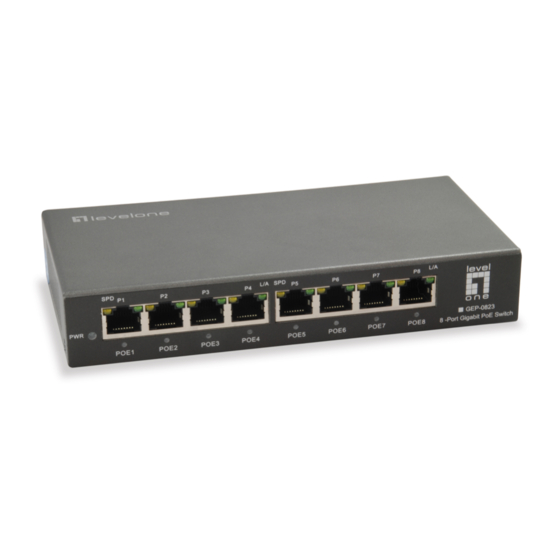
1. Front Panel
The front panel of PoE switch consists of 8 Auto-Sensing
10/100/1000Mbps Ethernet RJ-45 ports. The power LED
and LED indicators of all ports are also located on the front
panel.
Fig.2 Switch Front Panel
Rear Panel
The rear panel of the switch indicates an DC inlet power
socket, which accepts 52V DC input power.
Fig.3 Switch Rear Panel
Advertisement
Table of Contents

Related Manuals for LevelOne GEP-0823


Summary of Contents for LevelOne GEP-0823
- Page 1 100 meters (or 328 feet). They Fig.1 Basic Switch Connection also support standard Auto-MDI/MDI-X that can detect the Panel GEP-0823 type of connection to any Ethernet device without requiring 1. Front Panel User Manual special straight or crossover cables.
- Page 2 Explanation for LED indicators 5. PSE Pinout: PIN1/2: Pos(+), PIN3/6:Neg(-) 2. Link failure : 6. Operation temperature: -20℃~70 ℃ The LED indicators serve as device status monitoring and Check the L/A LED on the switch try another port on 7. Storage temperature: -40℃~75 ℃ error display.
Need help?
Do you have a question about the GEP-0823 and is the answer not in the manual?
Questions and answers