Table of Contents
Advertisement
Model No. NETL99810.0
USERʼS MANUAL
Serial No.
Write the serial number in the space
above for reference.
Serial Number
Decal
QUESTIONS?
If you have questions, or if there are
missing parts, please contact us:
UK
Call: 08457 089 009
From Ireland: 053 92 36102
Website: www.iconsupport.eu
E-mail: csuk@iconeurope.com
Write:
ICON Health & Fitness, Ltd.
c/o HI Group PLC
Express Way
Whitwood, West Yorkshire
WF10 5QJ
UK
AUSTRALIA
Call: 1-800-237-173
E-mail:
australiacc@iconfitness.com
CAUTION
Read all precautions and instruc-
tions in this manual before using
this equipment. Save this manual
www.iconeurope.com
for future reference.
Advertisement
Table of Contents

Related Manuals for NordicTrack T9.1


Summary of Contents for NordicTrack T9.1
- Page 1 Model No. NETL99810.0 USERʼS MANUAL Serial No. Write the serial number in the space above for reference. Serial Number Decal QUESTIONS? If you have questions, or if there are missing parts, please contact us: Call: 08457 089 009 From Ireland: 053 92 36102 Website: www.iconsupport.eu E-mail: csuk@iconeurope.com Write:...
-
Page 2: Table Of Contents
Apply the decal in the location shown. Note: The decals may not be shown at actual size. NordicTrack is a registered trademark of ICON IP, Inc. -
Page 3: Important Precautions
IMPORTANT PRECAUTIONS WARNING: To reduce the risk of serious injury, read all important precautions and in- structions in this manual and all warnings on your treadmill before using your treadmill. ICON as- sumes no responsibility for personal injury or property damage sustained by or through the use of this product. - Page 4 19. Never leave the treadmill unattended while it 23. Inspect and properly tighten all parts of the is running. Always remove the key, unplug treadmill regularly. DANGER: the power cord, and press the power switch into the off position when the treadmill is not Always unplug the power in use.
-
Page 5: Before You Begin
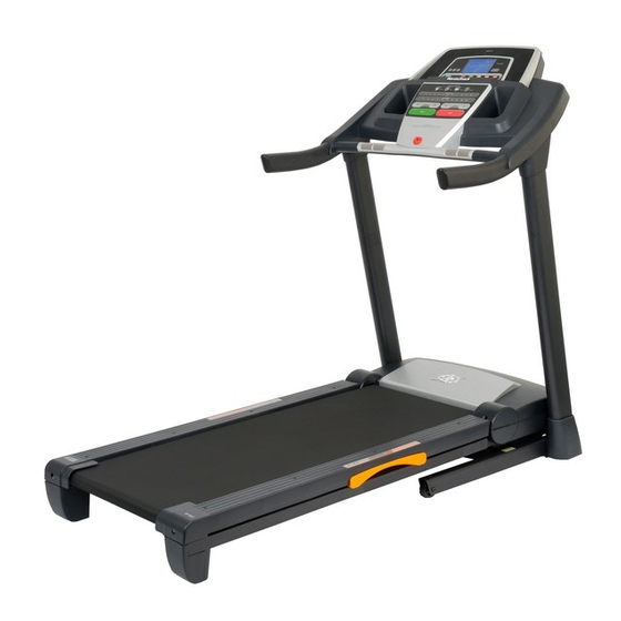
BEFORE YOU BEGIN Thank you for selecting the revolutionary NordicTrack ing this manual, please see the front cover of this man- ® T 9.1 treadmill. The T 9.1 treadmill offers an impres- ual. To help us assist you, please note the product sive selection of features designed to make your work- model number and serial number before contacting us. -
Page 6: Assembly
ASSEMBLY Assembly requires two persons. Set the treadmill in a cleared area and remove all packing materials. Do not dispose of the packing materials until assembly is completed. Note: The underside of the treadmill walking belt is coated with high-performance lubricant. During shipping, some lubricant may be transferred to the top of the walking belt or the shipping carton. -
Page 7: Frame (55) So That The Treadmill Is More Stable
1. Make sure that the power cord is unplugged. Remove the 3/8" Nut (10), the 3/8" x 2" Bolt (8), and the shipping bracket (A) from the Base (95). Repeat this step on the other side of the treadmill. The 3/8" Nuts (10) and the 3/8" x 2" Bolts (8) will be used in assembly steps 3 and 6. - Page 8 3. Attach a Wheel (96) to the Base (95) with the 3/8" x 2" Bolt (8) and the 3/8" Nut (10) that you removed in step 1. Do not overtighten the Nut; the Wheel must turn freely. Press a Base Cap (89) into the Base (95). 4.
-
Page 9: And The Shipping Bracket (C
6. With the help of a second person, carefully tip the treadmill onto its right side. Partially fold the Frame (55) so that the treadmill is more stable; do not fully fold the Frame yet. Remove and discard the two indicated bolts (B) and the shipping bracket (C). - Page 10 8. Identify the Left Base Cover (88) and the Right Base Cover (91). Slide the Left Base Cover onto the Left Upright (84) and the Right Base Cover onto the Right Upright (85). 9. Identify the Left Upright Cover (80). Slide the Left Upright Cover onto the Left Upright (84).
- Page 11 10. Slide the Right Upright Cover (86) onto the Right Upright (85). Remove the tie from the bracket on the Right Handrail (83). If necessary, press the 5/16" Cage Nut (38) back into place. Bracket Hold the Right Handrail (83) near the Right Upright (85).
- Page 12 12. IMPORTANT: To avoid damaging the Crossbar (107), do not use power tools and do not overtighten the #10 x 3/4" Screws (2). First Orient the Crossbar (107) as shown. Attach the Crossbar to the Handrails (82, 83) with four #10 x 3/4"...
- Page 13 14. Set the console assembly on the Left and Right Handrails (82, 83). Be careful not to pinch any Console wires. Insert the excess Upright Wire (87) into Assembly the Right Handrail. Attach the console assembly to the Crossbar (107) with six #8 x 3/4" Screws (1). Start all six Screws, and then tighten each of them.
- Page 14 16. Raise the Frame (55) to the position shown. Have a second person hold the Frame until this step is completed. Orient the Storage Latch (51) so that the large barrel and the latch knob are oriented as shown. Attach the Latch Bracket (6) and Storage Latch (51) to the Base (95) with two 3/8"...
-
Page 15: How To Use The Chest Pulse Sensor
HOW TO USE THE CHEST PULSE SENSOR HOW TO PUT ON THE CHEST PULSE SENSOR may remain activated longer than necessary, drain- ing the battery prematurely. The chest pulse sensor consists of two components: the chest strap and the sensor unit. Insert the tab on •... -
Page 16: Operation And Adjustment
OPERATION AND ADJUSTMENT THE PRE-LUBRICATED WALKING BELT 2. If you are plugging in the power cord in Australia, go to step 3. Your treadmill features a walking belt coated with high- performance lubricant. IMPORTANT: Never apply sil- If you are plugging in the power cord in the UK, icone spray or other substances to the walking belt first press the pins on the power cord into the metal or the walking platform. - Page 17 CONSOLE DIAGRAM FEATURES OF THE CONSOLE You can even listen to your favorite workout music or audio books with the consoleʼs stereo sound system The treadmill console offers an impressive array of while you exercise. features designed to make your workouts more effec- To turn on the power, see page 18.
-
Page 18: To Use The Manual Mode
HOW TO TURN ON THE POWER 3. Start the walking belt. IMPORTANT: If the treadmill has been exposed to To start the walking belt, press the Start button, the cold temperatures, allow it to warm to room tem- Speed increase button, or one of the Quick Speed perature before turning on the power. - Page 19 6. Measure your heart rate if desired. • The incline level of the treadmill Note: If you use the handgrip pulse sensor and • The number of vertical feet you have climbed the chest pulse sensor at the same time, the console will not display your heart rate accu- •...
- Page 20 HOW TO USE AN ONBOARD WORKOUT During the workout, the 1. Insert the key into the console. profiles on the speed and in- See HOW TO TURN ON THE POWER on page 18. cline tabs will Current Segment show your 2.
- Page 21 HOW TO USE AN IFIT LIVE WORKOUT If the speed or incline setting is too high or too low at any time during the workout, you can manually 1. Insert the key into the console. override the setting by pressing the Speed or Incline buttons;...
- Page 22 7. Measure your heart rate if desired. When you select an iFit Live workout, the display will show the duration of the workout, the distance you will walk or run, and the approximate number of See step 6 on page 19. calories you will burn.
- Page 23 THE INFORMATION MODE demo mode, press the Enter button or the Speed de- crease button. The console features an information mode that keeps track of treadmill information and allows you to person- Press the decrease button next to the Enter button. alize console settings.
-
Page 24: How To Fold And Move The Treadmill
HOW TO FOLD AND MOVE THE TREADMILL HOW TO FOLD THE TREADMILL HOW TO MOVE THE TREADMILL To avoid damaging the treadmill, adjust the incline Before moving the treadmill, fold it as described at the to the lowest position before you fold the treadmill. left. -
Page 25: Troubleshooting
TROUBLESHOOTING Most treadmill problems can be solved by following the simple steps below. Find the symptom that applies, and follow the steps listed. If further assistance is needed, see the front cover of this manual. PROBLEM: The power does not turn on SOLUTION: a. - Page 26 Remove the three #8 x 3/4" Screws (1) and care- fully pivot the Motor Hood (62) off. Locate the Reed Switch (73) and the Magnet (47) on the left side of the Pulley (48). Turn the Pulley until the Magnet is aligned with the Reed Switch. Make sure that the gap between the Magnet and 1/8 in.
- Page 27 PROBLEM: The walking belt is off-center or slips when walked on SOLUTION: a. If the walking belt is off-center, first remove the key and UNPLUG THE POWER CORD. If the walking belt has shifted to the left, use the hex key to turn the left idler roller bolt clockwise 1/2 of a turn;...
-
Page 28: Exercise Guidelines
EXERCISE GUIDELINES WARNING: Burning Fat—To burn fat effectively, you must exer- cise at a low intensity level for a sustained period of Before beginning this time. During the first few minutes of exercise, your or any exercise program, consult your physi- body uses carbohydrate calories for energy. - Page 29 SUGGESTED STRETCHES The correct form for several basic stretches is shown at the right. Move slowly as you stretch—never bounce. 1. Toe Touch Stretch Stand with your knees bent slightly and slowly bend forward from your hips. Allow your back and shoulders to relax as you reach down toward your toes as far as possible.
-
Page 30: Part List
PART LIST—Model No. NETL99810.0 R0810A To locate the parts listed below, see the EXPLODED DRAWING near the end of this manual. Key No. Qty. Description Key No. Qty. Description #8 x 3/4" Screw Storage Latch #10 x 3/4" Screw Console Ground Wire 3/8"... - Page 31 Key No. Qty. Description Key No. Qty. Description Console Filter Console Frame Transformer Tray Motor Bushing Module Housing Motor Isolator Console Clamp Power Cord Adapter Console Base Chest Pulse Strap Crossbar #8 x 1/2" Module Screw Access Door – Userʼs Manual Electronic Bracket Note: Specifications are subject to change without notice.
-
Page 32: Exploded Drawing
EXPLODED DRAWING A—Model No. NETL99810.0 R0810A... - Page 33 EXPLODED DRAWING B—Model No. NETL99810.0 R0810A...
- Page 34 EXPLODED DRAWING C—Model No. NETL99810.0 R0810A...
- Page 35 EXPLODED DRAWING D—Model No. NETL99810.0 R0810A...
-
Page 36: Ordering Replacement Parts
ORDERING REPLACEMENT PARTS To order replacement parts, see the front cover of this manual. To help us assist you, please be prepared to pro- vide the following information when contacting us: • the model number and the serial number of the product (see the front cover of this manual) •...
Need help?
Do you have a question about the T9.1 and is the answer not in the manual?
Questions and answers