Table of Contents
Advertisement
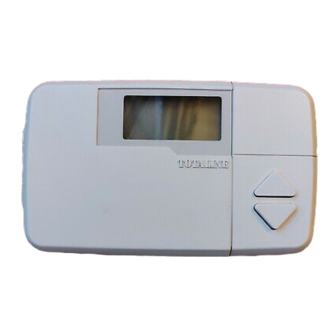
TOTALINE
1c.eps
gold-1.pdf
SAFETY CONSIDERATIONS . . . . . . . . . . . . . . . . . . . . . . 1
GENERAL . . . . . . . . . . . . . . . . . . . . . . . . . . . . . . . . . . . . . . . . 1
INSTALLATION CONSIDERATIONS . . . . . . . . . . . . . .1,2
Models . . . . . . . . . . . . . . . . . . . . . . . . . . . . . . . . . . . . . . . . . . . 1
Outdoor Temperature Sensing . . . . . . . . . . . . . . . . . . . 1
INSTALLATION . . . . . . . . . . . . . . . . . . . . . . . . . . . . . . . . 2-14
Step 1 - Thermostat Location . . . . . . . . . . . . . . . . . . . 2
Step 2 - Set DIP Switches . . . . . . . . . . . . . . . . . . . . . . . 2
Step 3 - Install Thermostat . . . . . . . . . . . . . . . . . . . . . . 2
Step 4 - Space Temperature Averaging . . . . . . . . 10
Step 5 - Set Thermostat Configuration . . . . . . . . . 10
Step 6 - Check Thermostat Operation . . . . . . . . . . 12
Step 7 - Select Thermostat Operation
Settings. . . . . . . . . . . . . . . . . . . . . . . . . . . . . . . . . . . . . . . 13
Step 8 - Set Current Time . . . . . . . . . . . . . . . . . . . . . . 13
Step 9 - Set Current Day . . . . . . . . . . . . . . . . . . . . . . . 13
Schedules . . . . . . . . . . . . . . . . . . . . . . . . . . . . . . . . . . . . 13
Step 11 - Final Checklist . . . . . . . . . . . . . . . . . . . . . . . 13
OPERATION . . . . . . . . . . . . . . . . . . . . . . . . . . . . . . . . . . .14,15
Hold, Fan, and Mode Button Operation . . . . . . . . . . 14
Outdoor Temperature . . . . . . . . . . . . . . . . . . . . . . . . . . . 14
Thermostat Output Assignments. . . . . . . . . . . . . . . . 14
Five-Minute Compressor Timeguard . . . . . . . . . . . . 14
Fifteen-Minute Cycle Timer . . . . . . . . . . . . . . . . . . . . . . 14
Fifteen-Minute Staging Timer. . . . . . . . . . . . . . . . . . . . 14
Three-Minute Minimum On Time . . . . . . . . . . . . . . . . 14
Heating/Cooling Set Points. . . . . . . . . . . . . . . . . . . . . . 14
Auto-Changeover Timer . . . . . . . . . . . . . . . . . . . . . . . . . 14
Power-On Check . . . . . . . . . . . . . . . . . . . . . . . . . . . . . . . . 14
Error Codes . . . . . . . . . . . . . . . . . . . . . . . . . . . . . . . . . . . . . 15
Smart Recovery (Heating Mode Only) . . . . . . . . . . . 15
TROUBLESHOOTING. . . . . . . . . . . . . . . . . . . . . . . . . . . . 15
CONFIGURATION RECORD . . . . . . . . . . . . . . . . . . . 16
IMPORTANT: Read entire instructions before start-
ing the installation.
SAFETY CONSIDERATIONS
Read and follow manufacturer instructions carefully. Fol-
low all local electrical codes during installation. All wiring
must conform to local and national electrical codes. Improper
wiring or installation may damage the thermostat.
Recognize safety information. This is the safety alert sym-
bol
. When the safety alert symbol is present on equipment
or in the instruction manual, be alert to the potential for person-
al injury.
Manufacturer reserves the right to
discontinue, or change at any time,
specifications or designs without notice
and without incurring obligations.
INSTALLATION
AND OPERATING
INSTRUCTIONS
Part No. P274-1100, 1200, 1300
CONTENTS
REPLACEMENT COMPONENTS DIVISION
© CARRIER CORPORATION 2007 1-07
PRINTED IN U.S.A.
Understand the signal words DANGER, WARNING, and
CAUTION. These words are used with the safety alert symbol.
Page
DANGER identifies the most serious hazards which will result
in severe personal injury or death. WARNING signifies a haz-
ard which could result in personal injury or death. CAUTION
is used to identify unsafe practices which would result in minor
personal injury or property damage.
Totaline® 7-day, programmable thermostats are wall-mount-
ed, low-voltage thermostats which maintain room temperature
by controlling the operation of an HVAC (heating, ventilation,
and air-conditioning) system. Separate heating and cooling set
points and auto-changeover capability allow occupied and un-
occupied programming for energy savings.
All programmable thermostats allow up to 4 time/tempera-
ture settings to be programmed per 24-hr period. Each thermo-
stat stores programs for 7 independent days. Batteries are not
required. During power interruption, the internal memory
stores comfort schedules for an unlimited time while the clock
continues to run for at least 72 hours.
INSTALLATION CONSIDERATIONS
Models -
There are 3 different models. Ensure the proper
thermostat is selected for the intended application. Refer to
Fig. 1 for thermostat dimensions. Select from the following
models:
1. P274-1100 (air conditioner [AC]) - 1-stage cool,
1-stage heat for air-conditioning systems only
2. P274-1200 (heat pump [HP]) - 1-stage cool, 2-stage
heat for either heat pump or air conditioner systems
with 2-stage heat
3. P274-1300 (2-speed) - 2-stage cool, 2-stage heat for
2-speed AC systems, or 2-stage cool, 3-stage heat for
2-speed HP systems, or 1-stage cool, 4-stage heat for
1-speed HP with special 3-stage electric heat
Outdoor Temperature Sensing -
ble thermostats can be equipped with an optional outdoor tem-
perature sensor, part no. TSTATXXSEN01-B. If this option is
to be installed, plan thermostat installation so that 2 wires can
be run from the thermostat to an outdoor location. Refer to the
installation instructions provided with the outdoor temperature
sensor for necessary connections.
Residential
Programmable
Thermostats
GENERAL
All programma-
LITERATURE NUMBER P274-8SI
REPLACES: NEW
CATALOG NUMBER 570-502
Advertisement
Table of Contents

Related Manuals for TOTALINE Gold P274-1100


Summary of Contents for TOTALINE Gold P274-1100
-
Page 1: Table Of Contents
Fifteen-Minute Staging Timer....14 1. P274-1100 (air conditioner [AC]) — 1-stage cool, Three-Minute Minimum On Time ....14 1-stage heat for air-conditioning systems only Heating/Cooling Set Points. -
Page 2: Installation
AC mode, this extra relay is converted to a second stage heat output. This allows thermostat control of 2-stage fur- naces or 2-stage strip heat with AC systems (AC mode wiring Fig. 1 — Totaline® Residential also uses W rather than Y for first-stage heat). Programmable Thermostat... - Page 3 NOTE: When a remote space temperature sensor or out- Fig. 2-24 for proper wiring depending on model no. door-air sensor is used, an additional conductor should be and intended application. provided for grounding of the shield. Improper wiring or installation may cause damage to the Terminals S2 and C are internally connected.
- Page 4 MODEL 1100 TYPICAL SINGLE-SPEED THERMOSTAT FAN COIL AIR CONDITIONER MODEL 1100 SINGLE-STAGE SINGLE-SPEED THERMOSTAT FURNACE AIR CONDITIONER 24 VAC HOT 24 VAC HOT COOL STAGE 1 Y/Y2 HEAT STAGE 1 W/W1 HEAT STAGE 1 W/W1 COOL STAGE 1 Y/Y2 O/W2 O/W2 Y1/W2 Y1/W2...
- Page 5 TWO-STAGE OR MODEL 1200 SINGLE-SPEED VARIABLE-SPEED THERMOSTAT AIR CONDITIONER FURNACE SPLICE MODEL 1100 THERMOSTAT 24 VAC HOT 24 VAC HOT HEAT STAGE 1 W/W1 W/W1 HEAT STAGE 1 W/W1 COOL STAGE 1 Y/Y2 Y/Y2 COOL STAGE 1 Y/Y2 HEAT STAGE 2 O/W2 O/W2 Y1/W2...
- Page 6 HEATER MODEL 1200 SPLICE MODEL 1200 TYPICAL SINGLE-SPEED CONTROL BOX THERMOSTAT THERMOSTAT FAN COIL HEAT PUMP COOL STAGE 1 Y/Y2 24 VAC HOT HEAT STAGE 1 RVS COOLING W/W1 O/W2 RED (TRAN) COOL/HEAT Y/Y2 Y1/W2 STAGE 1 O/W2 HEAT STAGE 2 HEAT STAGE 2 W/W1 Y1/W2...
- Page 7 HEATER SPLICE MODEL 1200 CONTROL BOX THERMOSTAT MODEL 1300 SINGLE-STAGE TWO-SPEED THERMOSTAT FURNACE AIR CONDITIONER HEAT STAGE 2 W/W1 COOL STAGE 1 Y1/W2 O/W2 RVS COOLING Y1/W2 HEAT STAGE 1 W/W1 COOL/HEAT Y/Y2 STAGE 1 COOL STAGE 2 Y/Y2 O/W2 24 VAC HOT 24 VAC HOT 24 VAC COMM...
- Page 8 MODEL 1300 TWO-STAGE OR TWO-SPEED THERMOSTAT VARIABLE-SPEED HEAT PUMP MODEL 1300 TYPICAL TWO-SPEED FURNACE THERMOSTAT FAN COIL AIR CONDITIONER Y1 * COOL/HEAT Y1/W2 24 VAC HOT STAGE 1 RVS COOLING O/W2 W/W1 HEAT STAGE 3 W/W1 HEAT STAGE 1 W/W1 COOL/HEAT Y/Y2 Y/Y2...
- Page 9 MODEL 1300 TWO-SPEED MODEL 1300 SINGLE-SPEED THERMOSTAT EASY SELECT AIR CONDITIONER THERMOSTAT EASY SELECT HEAT PUMP TERMINAL BOARD TERMINAL BOARD JUMPER JUMPER 24 VAC HOT 24 VAC HOT COOL STAGE 1 Y1/W2 COOL/HEAT Y/Y2 Y/Y2 STAGE 1 REMOVE COOL STAGE 2 Y/Y2 Y/Y2 HEAT STAGE 2...
-
Page 10: Step 4 - Space Temperature Averaging
Table 2. ration value (larger) on the left of the thermostat display will NOTE: Only Totaline® sensors (P/N P274-0401) may be flash. Change the configuration value with the Up and Down used for standard space temperature sensor averaging. Sen- Arrow buttons. - Page 11 TO THERMOSTAT SENSOR 1 SENSOR 2 SENSOR 3 SENSOR 4 SPACE TEMPERATURE AVERAGING — 4 SENSOR APPLICATION TO THERMOSTAT SENSOR 3 SENSOR 1 SENSOR 2 SENSOR 6 SENSOR 4 SENSOR 5 LEGEND — Terminal Block Factory Wiring Field Wiring SENSOR 8 SENSOR 9 SENSOR 7 SPACE TEMPERATURE AVERAGING —...
-
Page 12: Step 6 - Check Thermostat Operation
ANTICIPATOR ADJUSTMENT SELECTION (Option No. ENABLE AUTO MODE (Option No. 15) — The enable au- 01) — The anticipator adjustment selection controls the sensi- to mode selection allows the installer to enable or disable tivity and cycle rate of the thermostat. Higher numbers AUTO mode (automatic changeover between heat and cool). -
Page 13: Settings
Arrow and Fan buttons together (increase tempera- schedule will be displayed above the clock and the cur- ture). This will make the triangle stay on and turn Cool rent programming time period of that day will be dis- Stage 1 on. For actual outputs, refer to Table 4, making played. -
Page 14: Operation
Table 4 — Thermostat Output Assignments THERMOSTAT OUTPUT AC/HP STAGING MODEL OUTDOOR HEAT HEAT HEAT HEAT COOL COOL SWITCH SWTICH REVERSE P274- UNIT COMMON STAGE STAGE STAGE STAGE STAGE STAGE VALVE 1100 EITHER EITHER W/W1 Y/Y2 EITHER Y/Y2 W/W1 Y/Y2 O/W2 1200 EITHER... -
Page 15: Error Codes
Error Codes — Smart Recovery will not occur if Hold is active. Smart Re- If an error is present, the thermostat will covery will also be cancelled if the heating set point or time of display an error code. See Table 5. day are changed. -
Page 16: Programmable Thermostat Configuration Record
PROGRAMMABLE THERMOSTAT CONFIGURATION RECORD Date Owner/Operator Thermostat Model No. A) Hardware Configuration Switch A Zoning Selection (OFF = disable, ON = enable) Switch B Smart Recovery (OFF = enable, ON = disable) Switch C Heat Pump Operation (OFF = enable, ON = disable) Switch D Intelligent Heat Staging (OFF = disable, ON = enable) B) Configuration Options...
Need help?
Do you have a question about the Gold P274-1100 and is the answer not in the manual?
Questions and answers