Table of Contents
Advertisement
Quick Links
Supported Model
C4-DIN-8ESW-E
8-Port Ethernet Switch (DIN Rail)
Introduction
The Control4® 8-Port Ethernet Switch is part of the Control4 Panelized Lighting
System. It installs in the Control4 5-Slot or 2-Slot Panel or in any standard DIN rail
panel with 35mm rails. The Ethernet Switch is a standard 8-port 10/100 switch
that allows a single Ethernet CAT5e cable to be pulled into the panel, and then
distributed to up to seven (7) other Control4 panelized lighting devices in the
panel.
Box Contents
8-Port Ethernet Switch
Warranty Card
8-Port Ethernet Switch Wiring Guide
Warnings and Considerations
Improper use or installation can cause SERIOUS INJURY,
WARNING!
DEATH or LOSS/DAMAGE OF PROPERTY.
ATTENTION!
Une mauvaise utilisation ou installation peut entraîner des
blessures graves, décès ou perte / dommages à la propriété.
This device must be protected by a circuit breaker (20A max).
WARNING!
ATTENTION!
Cet appareil doit étre protègè par un disjoncteur (20A max.)
WARNING!
Ensure that all circuit breakers feeding into the panel are OFF
before installing or servicing the devices.
ATTENTION!
Assurez-vous que tous les disjoncteurs d'alimentation dans
le panneau sont éteints avant d'installer ou de réparer l'appareil.
IMPORTANT!
Using this product in a manner other than outlined in this
document voids your warranty. Further, Control4 is NOT liable for any
damage incurred with the misuse of this product. See "Troubleshooting."
IMPORTANT!
Changes or modifications not expressly approved by
Control4 could void the user's authority to operate the equipment.
IMPORTANT!
The Ethernet Switch should be installed by a licensed
electrician in accordance with all national and local electrical codes.
Requirements and Specifications
Prior to installing this product, ensure that the Control4 5-Slot or 2-Slot Panel or
that the cabinet to house the switch has been installed.
8-Port
Ethernet Switch
Installation Guide
(this document)
™
The 8-Port Ethernet Switch specifications include:
Power
Operating Temperature
Power Consumption
Communications
Connectors
Humidity
Storage
Dimensions (HxWxD)
DIN Module Width
Weight
Shipping Weight
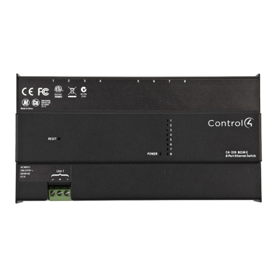
Front View
Figure 1. Front View
3
1
Power LED
2
Link/Activity LEDs
3
Reset button
4
Ethernet RJ-45 Connectors
5
Line Voltage Connector
Pre-Installation Instructions
Before You Install in a Control4 Panel
1
Use Composer Pro to add the 8-Port Ethernet Switch to a project, define its
location in a panel, and print the panel report. See the Composer Pro User
Guide for details.
2
Install the panel following the instructions in the 5-Slot and 2-Slot Panel
Installation Guide.
3
Install and wire the Terminal Block for the 8-Port Ethernet Switch following
the instructions in the Terminal Block Installation Guide and in the location
defined by the Composer Pro panel reports.
Before You Install in a Third-Party DIN Rail Panel
1
Install the third-party panel according to the third-party instructions.
110V-277VAc, 50/60 Hz
32˚F to 104˚F (0˚C to 40˚C)
2W
10/100 Ethernet
Three (3) Screw Terminals (Line,
Neutral, Ground), one (1) 26AWG
to 12AWG (.12 - 4mm
minal
Eight (8) RJ-45 Ethernet
5% - 95%
Non-condensing
-4˚ F - 158˚ F
(-20˚ C - 70˚ C)
8.5" x 4.3" x 2.3" (215 mm x 109
mm x 57 mm)
12M
2.3 lbs. (1.04 kg)
2.8 lbs. (1.27 kg)
4
1
5
2
) per ter-
2
Advertisement
Table of Contents

Related Manuals for Control 4 C4-DIN-8ESW-E


Summary of Contents for Control 4 C4-DIN-8ESW-E
-
Page 1: Installation Guide
8.5” x 4.3” x 2.3” (215 mm x 109 Dimensions (HxWxD) System. It installs in the Control4 5-Slot or 2-Slot Panel or in any standard DIN rail mm x 57 mm) panel with 35mm rails. The Ethernet Switch is a standard 8-port 10/100 switch... -
Page 2: Installation Instructions
With the right side already in place, push forward on the left side of the 8-Port Ethernet Switch to snap it onto the rail (see Figure 2). Figure 2. Snap on the Ethernet Switch - Control4 Panels NOTE: To remove the module, push the module toward the bottom, rotate the module up, and lift it off. -
Page 3: Additional Information
Warranty card or visit www.control4.com/ warranty. About this Document Part Number: 200-00208 Rev. B 3/04/2013 Wiring Diagrams The wiring diagrams for the Control4 panels and third-party panels are available in the 8-Port Ethernet Switch Wiring Guide. - Page 4 Copyright ©2013 Control4. All rights reserved. Control4, the Control4 logo, the Control4 iQ logo and the Control4 certified logo are registered trademarks or trademarks of Control4 Corporation in the United States and/or other countries. All other names and brands may be claimed as the property of their respective owners Pricing and specifications are subject to change without notice...
Need help?
Do you have a question about the C4-DIN-8ESW-E and is the answer not in the manual?
Questions and answers