Table of Contents
Advertisement
Quick Links
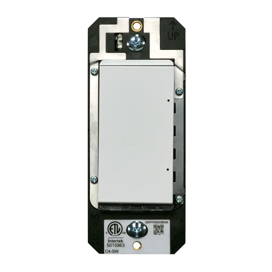
Switch
Installation Guide
Supported model
•
C4-SW240 Switch. 240V
Introduction
The Control4® Switch operates independently or as part of a Control4 home
automation system. It installs in a standard back box using typical wiring standards
and communicates to the Control4 system using a wireless connection.
Box contents
•
Switch
•
Terminal block
•
Warranty card
Switch Installation Guide (this document)
•
Specifications and supported load types
The specifications are described below.
Model number
Power requirements
Power consumption
Load types and ratings
Supported load types
Maximum load
Operational temperature
Humidity
Storage
Control communications
Wallbox volume
Weight
Shipping weight
™
C4-SW240-xx
220V AC-240V AC +/-10%, 50/60 Hz
This device requires a neutral connection. See
the "Sample Wiring Configurations" later in this
guide.
950mW
Incandescent, halogen, electronic (solid
state) low voltage (ELV) transformers,
magnetic (iron core, inductive) low voltage
(MLV) transformers, fluorescents, compact
fluorescents, LEDs, motors
10A, 1/2HP
Environmental
0 to 40 ˚C (32 to 104 ˚F)
5% to 95% non-condensing
-20 to 70 ˚C (-4 to 158 ˚F)
Miscellaneous
Zigbee, IEEE 802.15.4, 2.4 GHz, 15-channel
spread spectrum radio
94.2 cubic centimeters (5.75 cubic inches)
0.05 kg (0.12 lb.)
0.08 kg (0.18 lb.)
Warnings and considerations
WARNING!
Turn OFF electrical power before installing or servicing this
product. Improper use or installation can cause SERIOUS INJURY, DEATH
or LOSS/DAMAGE OF PROPERTY.
WARNING!
This device must be protected by a circuit breaker (20A max).
WARNING!
Ground this device in accordance with the National Electric
Code (NEC) requirements. DO NOT rely solely upon the yoke plate's
contact with a metal back box for adequate grounding. Use the device's
ground wire to make a secure connection to the safety ground of the
electrical system.
IMPORTANT!
This device must be installed by a licensed electrician in
accordance with all national and local electrical codes.
If you are unsure about any part of these instructions,
IMPORTANT!
consult a qualified electrician.
IMPORTANT!
Use this device only with copper or copper-clad wire. Do
not use aluminum wiring. This product has not been approved for use with
aluminum wiring.
Using this product in a manner other than outlined in this
IMPORTANT!
document voids your warranty. Further, Control4 is NOT liable for any
damage incurred with the misuse of this product. See "Troubleshooting."
IMPORTANT!
Do NOT use a power screwdriver to install this device. If you
do, you may overtighten the screws and strip them. Also, overtightening
the screws may interfere with proper button operation.
IMPORTANT!
This is an electronic device with intricate components.
Handle and install with care!
When used in conjunction with an Auxiliary Keypad
IMPORTANT!
(C4-KA-xx), the wire connecting the Auxiliary Keypad to the switch must
not exceed 30 m (100 ft.) at 240V AC.
Installation instructions
1
Ensure that the location and intended use meet the following criteria:
•
Do not exceed the load capacity requirements of the switch. Refer to the
load ratings in the specifications above for details.
•
Install in accordance with all national and local electrical codes.
•
The range and performance of the wireless control system is highly
dependent on the following: (1) distance between devices; (2) layout
of the home; (3) walls separating devices; and (4) electrical equipment
located near devices.
2
Turn off the mains electrical power at the consumer unit. To ensure the wires
do NOT have power running to them, use an inductive voltage detector.
The back box wiring shown in this document is an example. Your
NOTE:
wire colors and functions may differ. If you are not sure which wires are
the Line In/Hot, Neutral, Load, Traveler, and Earth Ground wires, have a
trained electrician perform the installation.
3
Prepare each wire. Wire insulation should be stripped back 7mm from the
wire end (see Figure 1).
Advertisement
Table of Contents

Related Manuals for Control 4 C4-SW240


Summary of Contents for Control 4 C4-SW240
- Page 1 Use the device’s ground wire to make a secure connection to the safety ground of the electrical system. • C4-SW240 Switch. 240V IMPORTANT! This device must be installed by a licensed electrician in Introduction accordance with all national and local electrical codes.
- Page 2 Button tap sequences Figure 1. Strip wire insulation Function Button tap sequence (either top button only, or top-bottom-top) Identify Zigbee channel Reboot Factory reset 9-4-9 Leave mesh and reset 13-4-13 Troubleshooting Identify your wiring application, and then see the appropriate wiring diagram If the light does not turn on: in the “Sample Wiring Configurations”...
- Page 3 ™ Sample wiring configurations Figure 2. Single device location Figure 3. Multiple device location using Auxiliary Keypad Auxiliary Keypad Maximum length: 240V AC 30 m (100 ft.) Figure 4. Multiple device location using Configurable Keypad...
- Page 4 Copyright ©2021, Wirepath Home Systems, LLC. All rights reserved. Control4 and SnapAV and their respective logos are registered trademarks or trademarks of Wirepath Home Systems, LLC, dba “Control4” and/or dba “SnapAV” in the United States and/or other countries. 4Store, 4Sight, Control4 My Home, Snap AV, Araknis Networks, BakPak, Binary, Dragonfly, Episode, Luma, Mockupancy, Nearus, NEEO, Optiview, OvrC, Pakedge, Sense, Strong, Strong Evolve, Strong Versabox, SunBriteDS, SunBriteTV, Triad, Truvision, Visualint, WattBox, Wirepath, and Wirepath ONE are also registered trademarks or trademarks of Wirepath Home Systems, LLC.
Need help?
Do you have a question about the C4-SW240 and is the answer not in the manual?
Questions and answers