
Related Manuals for Genie EDVRH-4


Summary of Contents for Genie EDVRH-4
-
Page 1: Digital Video Recorder
EDVR-H Series DIGITAL VIDEO RECORDER User Guide EDVRH-4 4 Channels EDVR-8 8 Channels EDVR-16 16 Channels... -
Page 2: Safety Precautions
SAFETY PRECAUTIONS CAUTION: TO REDUCE THE RISK OF ELECTRIC SHOCK, DO NOT REMOVE COVER (OR BACK). NO USER SERVICEABLE PARTS INSIDE. REFER SERVICING TO QUALIFIED SERVICE PERSONNEL. The lightning flash with arrowhead symbol, within an equilateral triangle, is intended to alert the user to the presence of un insulated “dangerous voltage”... -
Page 3: Table Of Contents
Contents Disclaimer ....................4 Warning ....................4 Caution ....................6 Preventing Malfunction ................6 Package Contents .................. 7 I.CONTROLS ................... 8 1. Front Panel ...................... 8 2. Rear Panel Connectors ................. 11 3. Remote Controller ..................12 4. Virtual Keypad for Mouse Control.............. 13 II. - Page 4 6. Event ......................34 7. Device ......................35 7.1 GENERAL .......................... 35 7.2 ALARM ..........................36 8. Network Setup ....................37 8.1. IP setup ..........................37 8.2. E-Mail ..........................38 8.3 DDNS ..........................39 8.4. Router & Port Forwarding ....................40 8.5.
-
Page 5: Disclaimer
Disclaimer The information in this manual is believed to be accurate and reliable as of the date of publication. The information contained herein is subject to change without notice. Revisions or New editions to this publication may be issued to incorporate such change We makes no warranties for damages resulting from corrupted or lost data due to a mistaken operation or malfunction of the Digital Video Recorder, the software, the hard drives, personal computers, peripheral devices, or unapproved/unsupported devices. - Page 6 Do not use substances containing alcohol, benzene, thinners or other flammable substances to clean or maintain the equipment. The use of these substances may lead to fire. Use a dry cloth on a regular periodic basis and wipe away the dust and dirt that collects on the device.
-
Page 7: Caution
Caution Do not operate the appliance beyond its specified temperature, humidity or power source ratings. Do not use the appliance in an extreme environment where there is high temperature or high humidity. Use the device at temperatures within +0°C - +40°C (32°F - 104°F) and humidity below 90 %. -
Page 8: Package Contents
Package Contents Please check the package and contents for visible damage. If any components are damaged or missing, do not attempt to use the unit, contact the supplier immediately. If the unit must be returned, it must be shipped in the original packing box. CONTENTS QUANTITY REMARK... -
Page 9: I.controls
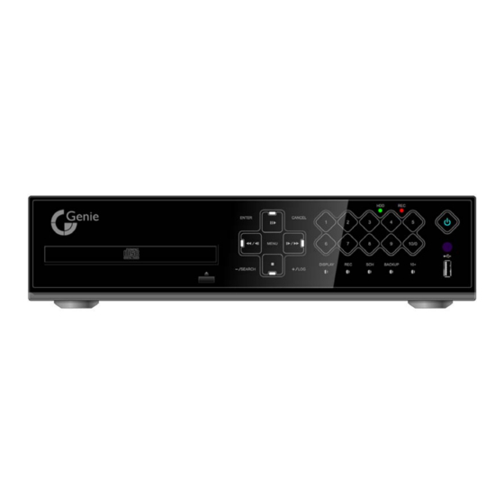
I.CONTROLS 1. Front Panel Mode indicator : 3 LEDs display the status of the Digital Video Recorder. Power (Blue), Recording (Red) and HDD (Green) Playback / Record control: These functions are used in Live Mode or Playback mode. 1) Direction buttons: In Menu setup mode, used to move the cursor. - Page 10 [Stop] : : This button stops playback [ F step or FF] ① Forward step : This button is used to move forward field by field (picture by picture) during STILL mode ② F.F. : This button is used to Fast Forwarding during PLAYBACK mode 3.
- Page 11 5. Funtion button 1) DISPLAY : Press this button to display the cameras in multi-screen view. 2) REC : Press this button to start recording. Press the button again or stop button to stop. 3) SCH [Schedule] : Press this button to make scheduled recording standby. Press the button again to stop.
-
Page 12: Rear Panel Connectors
2. Rear Panel Connectors 1) VGA : VGA out connector 2) HDMI : HDMI out connector 3) USB : For connecting USB compatible devices 4) LAN (RJ-45 Ethernet Port) : For connecting to remote PC via Ethernet network. 5) POWER : DC power Jack 6) CAM1~4, 1~8 or 1~16 : BNC input (Camera 1~4, 1~8 or 1~16) connectors 7) SPOT : Spot out connector 8) MONITOR (Composite Output) : BNC standard composite video output connector. -
Page 13: Remote Controller
Remote Controller DIGITAL VIDEO RECORDER... -
Page 14: Virtual Keypad For Mouse Control
Virtual Keypad for Mouse Control. This DVR can be controlled by Mouse. Connect a mouse via USB port before use. If you click right button of your mouse in Live mode and Playback mode, you will see following virtual Remote controllers respectively and Virtual Keypad will be shown to enter PASSWORD and Camera Name etc Repositioning TIME SEARCH... -
Page 15: Installation & Connections
II. INSTALLATION & CONNECTIONS 1. Camera, Monitor, Microphone, Alarm sensor and Power cord 1-1. System Configuration Diagram The following illustration is showing the fully installed system. DIGITAL VIDEO RECORDER... -
Page 16: Pc System Requirement For Network Connection
2. PC system requirement for Network connection. (a) Pentium-4 2.0GHz or higher (b) 256MB System Memory (c) 1,024 x 768 Display Resolution, 32 Bit color (d) Windows XP, VISTA (e) Spare 10/100-BaseT Ethernet Port (f) Microsoft DirectX 9.0c It is recommended to have DirectX 9.0c version in Client PC. DirectX 9.0c is available for download from Microsoft homepage (www.microsoft.com/windows/directx). -
Page 17: Iii.quick Setup
III.QUICK SETUP To turn on the DVR, press [POWER] button on the front panel or on the remote controller. When the Digital Video Recorder is powered on, the Live Viewing screen will appear in about 30sec. 1) Stop recording first to set QUICK SETUP menu. While DVR is recording, TIME and RECORD menu is not activated. -
Page 18: Time
1. TIME When the Digital Video Recorder is powered on for the very first time, it is important to set the exact date and time., 1) Select “Time” on TAP menu by using Directional buttons. 2) Enter the Date and Time by pressing numeric buttons on the remote controller or “–/+”... -
Page 19: Advanced
2.2. RECORD DAYS 1) Select RECORDING DAYS by pressing “–/+” buttons on the remote controller or on the unit. 2) Press [ENTER] button to exit a menu with saving changes. Press [ESC] to exit a menu without making changes. 2.3. PRIORITY 1) Select “RATE”... -
Page 20: Iv.live Viewing
IV.LIVE VIEWING 1. Display Overview Recording Mode Event Indicator Camera No and Title Status (1) Indicate Alarm In terminal is triggered by an alarm sensor. To disappear, press [CANCEL/ESC] button on remote controller or [CLR] button on the front panel. (2) Indicate Motion detected. -
Page 21: Multi Screen Display And Sequencing
: Displays Year, Month, Time and Date. : Show you the remaining recording time of the DVR. If remaining HDD capacity is less than 4GB, this blue “Recycling” icon will be shown up. 2. Multi screen Display and Sequencing 2.1 Full Screen Display Select any camera for Full screen display by pressing the Number button of the desired camera. -
Page 22: Repositioning
2.3 Repositioning To reposition a camera view on screen, 2.3.1. Virtual Remote controller ① Press button on virtual remote controller by using mouse, then Mark will be displayed on screen. Move icon to the desired position by pressing directional buttons on remote controller or virtual control pad. -
Page 23: Zooming
3. Zooming During live view mode or playback, it is possible to zoom into a section of the screen to get a close-up view of the screen. 1. To activate the digital zoom, select the full screen display of the camera you wish to zoom. -
Page 24: Hdmi Output
5. HDMI output To select video resolution of HDMI out put Press [1] + [LOG] button together on the front for more 5 seconds, then resolution will be changed [ 1024 x 768 - 1280 x 720P 1920 x 1080I ] in order. DIGITAL VIDEO RECORDER... -
Page 25: Operation
V. OPERATION 1. Main Menu Overview When the DVR is powered on, Live Viewing screen will appear after initialization about 30sec. Press [MENU] button to access the main menu. An Admin Password Box will appear. Enter the password using Numeric buttons on IR remote controller or CH increase button on Front Panel. -
Page 26: Display Option
2. Display Option 2.1. Display Setup 1. Use Direction buttons [ ] to select “DISPLAY” menu. Then, press [ENTER] button to display “DISPLAY SETUP”. 2. Use Left/Right buttons [ ] to select on TAP menu ( Selected items changed [ORANGE] color.. 3. -
Page 27: Sequential Setup (Auto Sequence)
2.2. Sequential Setup (Auto Sequence) ITEM DEFAULT ADJUSTMENT 2 Sec Specify the dwell time of each camera or Multi screen mode is DWELL TIME [-, +] button : displayed. Use [1 second ~ 30 second] SEQ. MODE None Select desired sequence mode to switching. Select the cameras to be included or excluded from the FULL SCREEN automatic sequencing. -
Page 28: Camera Setup
3. Camera Setup Use Direction buttons [ ] to select “CAMERA” menu. Then, press [ENTER] button to display “CAMERA”. 2. Use Left/Right buttons [ ] or Number button to select the Camera you wish to configure. 3. Use Down [ ] button to move specified menu and use Left/Right buttons [ ] to select other item. - Page 29 Motion Detected zones USE Numeric button to select Motion Grid. GRAY Will be cleared. Or Use <+> button to select Motion Grid at Front Panel. Running Man Icon will be activated. <+> button is used for selecting and cancel. Use <-> button to escape from Grid Menu.
- Page 30 Press Press Press Press Press Press Press Press SPACE <Insert characters from IR Remote Controller > DIGITAL VIDEO RECORDER...
-
Page 31: Continuous Recording (Normal Recording)
4. Continuous Recording (Normal Recording) The DVR comes with a certain preset settings from the factory. Therefore once the DVR is installed, immediate recording is possible after pressing the record buttons. By default, audio alarm, motion recording are off. 1. Use Direction buttons [ ] to select “RECORD”... - Page 32 < Approximate File Size> Quality NTSC UNIT 720x480 720x240 360x240 720x576 720x288 360x288 MIDDLE HIGH 10.2 12.3 SUPER 15.4 18.4 11.5 ULTRA 24.6 15.4 29.5 18.4 11.5 * It is calculated by theoretical, therefore it may be different depends on Video Signals or other conditions in actual.
-
Page 33: Schedule Recording
5. Schedule Recording The schedule chart shows a graphical representation of the defined record mode: Mode1~4. However, the schedules are only displayed if a corresponding schedule has been configured in the schedule menu. 1. Use Direction buttons [ ] to select “SCHEDULE” menu. Then, press [ENTER] button to display “Schedule Chart”. - Page 34 6. Define modes below. * Refer to Basic Recording for set up <Note> The recording time is set by 24H(00:00 - 23:59). You need to set 2 days if the setting is over one day. BEGIN MODE Monday 18:00 23:59 MODE 1 Tuesday 00:00...
-
Page 35: Event
6. Event 1. Use Direction buttons [ ] to select “EVENT” menu. Then, press [ENTER] button to display “EVENT”. 2. Use Direction buttons [ ] to select the Camera you wish to configure. 3. Use [-, +] button to change the value. In this section, users may set different event recording set up to select frame and image quality by each camera. -
Page 36: Device
7. Device The menus are displayed with options on the left-hand column and settings in the right hand column. A cursor (highlighted menu) can be moved using the Direction buttons [ 7.1 GENERAL ITEM ADJUSTMENT POST RECORD Determines the duration of the DVR continues record after Event detect. TIME [10SEC ~ 300 SEC ]. -
Page 37: Alarm
7.2 ALARM ITEM ADJUSTMENT ALL: Start to record All Alarm “ON” channel if there is any Alarm RECORD signal is triggered. CAMERA 1:1: Start to record the channel, which Alarm is triggered. ON: The buzzer Sounds if an alarm is triggered. The buzzer will sound for the duration of the RECORD TIME. -
Page 38: Network Setup
8. Network Setup The static service consists of an IP address that remains constant for the duration of the contract of the internet service, whereas the dynamic service consists of an IP address that frequently changes every time a new connection is made through the provided modem, or recurrently in a given period of time. -
Page 39: E-Mail
8.2. E-Mail This DVR allows you to specify the events that generate notification. Sends e-mail notification if an event occurs such as alarm or motion is detected and so forth. The mail server can use either the DVR mail server or your existing e-mail settings. The menus are displayed with options on the left-hand column and settings in the right hand column. -
Page 40: Ddns
8.3 DDNS This DVR offers free dynamic DNS update. It keeps track of your changing IP address. It’s easiest to use. The menus are displayed with options on the left-hand column and settings in the right hand column. A cursor (highlighted menu) can be moved using the Direction buttons [ ITEM ADJUSTMENT OFF : NO use of DDNS... -
Page 41: Router & Port Forwarding
8.4. Router & Port Forwarding The majority of any network will often consist of a single IP address which shares the internet access through a router. This IP address may be any external (public) static IP address or any dynamic IP address issued by the Internet Service Provider. The purpose of a router is to enable multiple personal computers and any other devices that require internet connection to access the internet simultaneously. - Page 42 1) Description of Location. A. LAN: Connect by Local IP. If you are connection from within your network, you only need to enter the IP address of the system into the S/W (ex. 192.168.0.50) B. WAN: Connect by DDNS. If you are connecting from outside your network, use the DDNS to configure the S/W.(Ex.
-
Page 43: Misc
8.5. MISC. ITEM ADJUSTMENT Select the network bandwidth to limit the amout of network resources BANDWIDTH allocated to client connection..The default is unlimited: “ 4 KBPS~ 8 MBPS” DIGITAL VIDEO RECORDER... -
Page 44: System Setup
9. System Setup 9.1. General 1. Use Direction buttons [ ] to select “SYSTEM” menu. Then, press [ENTER] button. 2. Use Left/Right buttons [ ] to select on TAP menu 3. Use Down button [ ] to specify the detail. Use [-, +] button to change the value. -
Page 45: Time
• Frame + CIF : Channel number 1-720x480(720x576) + Channel number 2~ 4/8/16 - : 360x240(360x280) ON: Reducing image flickering but less picture quality. PB DEINTERLACE OFF: Better picture quality for still image but having flicker for moving picture. RUN ON BOOT This is the purpose to start REC without pressing REC button when you turn on. -
Page 46: Account
9.3. Account Admin can define each user’s Authority. Select User 1~5 , then select Activate option on or off. When enabled, it will be possible to check individually under user settings: Monitoring, Playback, Back up, Network, Configuration (Main Menu Setup), Shutdown (Power off), Record stop. -
Page 47: Disk
9.4. DISK ITEM ADJUSTMENT 1. Stop the DVR completely before the disk format. 2. Use [-, +] button to change select device. * Internal HDD * USB – Memory Stick * USB – CD/DVD-RW * USB – HDD <Note> FORMAT When you format USB-HDD, it is formatted to FAT 32 format type. -
Page 48: Update
9.5. UPDATE. 1) Download the latest firmware file and copy to USB Flash memory stick in the Root Folder. 2) Turn on your DVR (If you are using, please stop the recording) 3) Plug USB memory stick into the front or rear USB port and check if USB icon shows up on the Status bar. 4) Move to upgrade menu and start upgrade by pressing [+]/[enter] button. -
Page 49: Info
9.6. INFO Press info button on IR remote to display the information. The other menu is blocked to move. This menu provides information such as listed below. Indicator CONDITION Display Current Language and you can change language here. LANGUAGE User cannot change Language while it’s under recording mode. MODEL Display Channel Number and compression. -
Page 50: Vi.pan/Tilt Zoom Control
VI.PAN/TILT ZOOM CONTROL 1. P.T. Z . Menu To activate the Pan/Tilt Control, select the full screen display of the camera you wish to control. Then press the [ ] button. Shortcut Menu box pops up, as shown below. P/T/Z/FOCUS <Note >... -
Page 51: Preset & Tour
The layout of the PTZ interface conforms to the layout of the front of the DVR or the remote controller. Menu button is the guide anchor position for all other buttons. When in PTZ interface mode, all buttons used for the PTZ related operation. ** Please Check below items before using PTZ Camera. - Page 52 4. PTZ Camera Model - PAN/TILT/ZOOM Camera List Esc/ Model Name Speed Preset Go to Tour A. Pan A.Tilt Enter NUVICO, NV 9600 BPS MERIT LILIN, PIH- 7000/7600 VCL, Orbiter Microsphere SAMSUNG, SCC-641 NEC, NC-21D SUNKWANG, SK2107 RESERVED D-MAX, PTZ PROTOCOL LG, LPT-A100L P/T/Z HONEYWELL, GCC- 655N...
- Page 53 ELMO, PTC-200C/400C NICECAM, MP-1xxx C&B TECH, CNB- PTZ102 IKEGAMI, PCS I-LAN IKEGAMI, lCD I-LAN Reserved TOA, SC80 SYSTEM CONTROLLER TOSHIBA, SC1000 BBV, TC 9600 BPS <Note> Speed has 0~8 steps 1 (Slow) – 8 (Fast) * 0 – Keep Pressing the button to increase speed DIGITAL VIDEO RECORDER...
-
Page 54: Vii.search/ Playback
VII.SEARCH/ PLAYBACK 1. Time Search 1. To start playback, press [Time Search] button, Time search Calendar Menu pops up, as shown below. 2. Use Left /Right button to change select Month on <Note> It will not be changed if there are no stored data on previous/next month. <Note>... -
Page 55: Log List Search/Alarm, Motion Search
2. Log List Search/Alarm, Motion Search The logs can be used to search and review directly to a point in time of the recorded data. Alarm, motion, video loss and system related logs can be searched and played back directly from the time of the incident. -
Page 56: Viii.backup
VIII.BACKUP 1. USB Memory Stick Backup 1. Insert a USB Memory Stick into the USB connection port on the front panel. Make sure your USB device has enough space before commencing backups. <Note> 2. Press [BACKUP] button on the front panel to display the backup menu. 3. -
Page 57: External Usb Hdd Backup
2. External USB HDD Backup External USB-HDD is recognized within 10 seconds after plug in USB Connection cable to UBS port in DVR. <Note> You must stop all recording before performing backup to external USB HDD. ONLY FAT 32 Format disk will be read through Window PC. Format is discussed in The data in FAT 32 format disk is not replayed on DVR. - Page 58 the system is in backup session, please do not perform playback. After backup process is finished, USB icon will be highlighted in white. When users get out of backup menu, the following message will be shown up to alert. DIGITAL VIDEO RECORDER...
-
Page 59: Cd/Dvd -Rw Backup
3. CD/DVD –RW Backup <Note> You must stop all recording before performing backup to CD/DVD RW. 1. Plug in USB connector into the USB connection port on the front panel. 2. Press [BACKUP] button to display the backup menu. <Note> For CD/DVD-RW back up, the select option is not available. -
Page 60: How To Play Backup Data In Usb Memory Stick Backup
4.How to Play Backup data in USB Memory Stick Backup 1. With “MCD Player” - Plug a USB memory stick into your PC. No software installation is required. 2. Double Click on “MCD Player” in the window and will play as follows. Channel Select Display Select Capture... -
Page 61: Back Up Range Setup
5. Back up Range Setup It is possible to set up backup range automatically on Time Search Menu[by Month, Date, Hour, Minute] Press [-] button to set backup Start time , press [+] button to set End. Selected time will be changed [Light Grey] Color. -
Page 62: Appendix 1: Web Server
Appendix 1: WEB SERVER Enter the IP address of the unit in the address page of the Internet Explorer. For example, type in http://192.168.0.250:7000 Above illustrates example of a unit when it is utilizing port 7000. You can either sign in with: admin or user. Next enter the password for the unit. - Page 63 Revised at Nov, 2009 DIGITAL VIDEO RECORDER...
-
Page 64: X.specificationation
X.SPECIFICATIONATION Specifications 4CH / 8CH / 16Ch Video Input 4 , 8, 16 Video Output HDMI, Composite, VGA, SPOT-OUT Video Compression H.264 Audio Compression G.711 Live Display Resolution NTSC 720*480, PAL 720*576 Alarm In/Out(Relay) 4ch - 4/1 , 8ch - 8/2 , 16ch - 16/2 Operating System EMBEDDED LINUX System Control... - Page 65 WEEE Symbol Information Correct Disposal of This Product (Waste Electrical & Electronic Equipment) (Applicable in the European Union and other European countries with separate collection systems) This marking shown on the product or its literature, indicates, that it should not be disposed with other household wastes at the end of its working life.
- Page 66 <Memo> DIGITAL VIDEO RECORDER...
Need help?
Do you have a question about the EDVRH-4 and is the answer not in the manual?
Questions and answers