
Subscribe to Our Youtube Channel
Related Manuals for Genie BDVR-8


Summary of Contents for Genie BDVR-8
-
Page 1: Digital Video Recorder
BDVR Series DIGITAL VIDEO RECORDER User Guide BDVR-4 4 Channels BDVR-8 8 Channels BDVR-16 16 Channels... -
Page 2: Safety Precautions
User Guide • Thank you for purchasing this Digital Video Recorder. • Before using the Digital Video Recorder, please ensure that you read and understand the User Guide. • Please retain the User Guide for future reference. • Before connecting and installing any third party cameras, monitors, alarms and computers, please refer to the appropriate instruction manual for their correct operation. -
Page 3: Table Of Contents
The lightning flash with arrowhead symbol, within an equilateral triangle, is intended to alert the user to the presence of un-insulated “dangerous voltage” within the product’s enclosure that may be of sufficient magnitude to constitute a risk of electric shock to persons. The exclamation point within an equilateral triangle is intended to alert the user to the presence of important operating and maintenance (servicing) instructions in the literature accompanying the appliance. - Page 4 1. TIME ......................20 2. RECORD ....................... 21 3. ADVANCED ....................22 IV.LIVE VIEWING ................... 23 1. Display Overview ..................23 2. Multi Screen Display and Sequencing ............24 2.1 Full Screen Display ....................... 24 2.2 Multi Screen Display and Sequencing Display............24 2.3 Repositioning .........................
- Page 5 1. P.T.Z. Menu ....................54 2. Preset & Tour ....................55 3. Custom Functions ..................55 VII.SEARCH/ PLAYBACK ..............58 1. Time Search ....................58 2. Log List Search/Alarm, Motion Search ............59 VIII.BACKUP ..................60 1. USB Memory Stick Backup ................60 2.
-
Page 6: Disclaimer
Disclaimer The information in this manual is believed to be accurate and reliable as of the date of publication. The information contained herein is subject to change without notice. Revisions or New editions to this publication may be issued to incorporate such change We makes no warranties for damages resulting from corrupted or lost data due to a mistaken operation or malfunction of the Digital Video Recorder, the software, the hard drives, personal computers, peripheral devices, or unapproved/unsupported devices. - Page 7 outlet. Contact a qualified service personnel authorised by your equipment distributor Do not attempt to disassemble or alter any part of the equipment that is not expressly described in this guide. Disassembly or alteration may result in high voltage electrical shock. Qualified service personnel authorised by your equipment distributor should conduct internal inspections, alterations and repairs.
-
Page 8: Caution
the leakage of corrosive liquids, fire, electrical shock, explosion or serious injury. Do not attempt to disassemble, alter or apply heat to the batteries. There is serious risk of injury due to an explosion. Immediately flush with water any area of the body, including the eyes and mouth, or clothing that comes into contact with the inner contents of the battery. -
Page 9: Package Contents
letting it adjust to temperature changes slowly before removing it from the bag. If Condensation forms inside the Digital Video Recorder. Stop using the equipment immediately if you detect condensation. Continued use may damage the equipment. Remove the power cord from the power outlet and wait until the moisture evaporates completely before resuming use. -
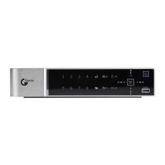
Page 10: I.controls
I.CONTROLS 1. Front Panel < 4 Channel > < 8 Channel> < 16 Channel> 1. Mode indicator : 3 LEDs display the status of the Digital Video Recorder. Power (Blue), Recording (Red) and HDD (Green) BDVR Manual Version 1.2... - Page 11 Playback / Record Control: These functions are used in Live mode or Playback mode. 1) Direction buttons: In Menu setup mode, are used to move the cursor. [LOG / Playback Stop] ① Log : Press this button to access the log list. ②...
- Page 12 5. . QUAD : Press this button to display the cameras in multi-screen view. 6. . Channel / Numeric Buttons : Press the buttons to enter data or make selections. Press “–” or “+” to enter appropriate numbers when prompted for a password, or appropriate dates in schedule option mode. [-, +] : To decrease settings, To increase settings 7.
-
Page 13: Rear Panel Connectors
2. Rear Panel Connectors 1) CAM1~4 or 1~8: BNC input (Camera 1~4 or 1~8) connectors 2) MONITOR (Composite Output) : BNC standard composite video output connector. 3) SPOT : Spot Out connector 4) AUDIO Input / SPEAKER (Output) connectors : RCA 5) VGA Out connector 6) LAN (RJ-45 Ethernet Port) : For connecting to remote PC via Ethernet network. -
Page 14: Remote Controller
3. Remote Controller BDVR Manual Version 1.2... -
Page 15: Virtual Keypad For Mouse Control
4. Virtual Keypad for Mouse Control. This DVR can be controlled by Mouse. Connect a mouse via USB port before use. Right clicking on the mouse in Live mode and Playback mode, displays the following Virtual Remote Controller and Virtual Keypad and can be used to enter PASSWORD and Camera Name etc Repositioning TIME SEARCH... -
Page 16: Installation & Connections
II. INSTALLATION & CONNECTIONS 1. Camera, Monitor, Microphone, Alarm Sensor and Power Cord 1-1. System Configuration Diagram The following illustration is showing a fully installed system. BDVR Manual Version 1.2... - Page 17 1-2. CAMERA This product can be installed for 4~16 cameras, dependant on Model number. Connect cameras to the VIDEO IN (BNC) on the back panel of the machine. To connect a PTZ camera, connect the PTZ camera’s control line to the RS-422 TX+, RS-422 TX- terminal and connect the video output to one out of VIDEO IN on the back panel of the product.
- Page 18 1.3 AUDIO The system has one channel audio input and output. To record and playback audio signals, connect an audio device (microphone) to the AUDIO IN (1 Vp-p @600 ohms) and speaker to the AUDIO OUTPUT (see illustration below). 1.4 MONITOR There are three video outputs (2 x BNC, 1 x VGA) on the rear panel of the system.
-
Page 19: Pc System Requirement For Network Connection
2. PC System Requirement for Network Connection. (a) Pentium-4 2.0GHz or higher (b) 256MB System Memory (c) 1,024 x 768 Display Resolution, 32 Bit colour (d) Windows XP, VISTA (e) Spare 10/100-BaseT Ethernet Port (f) Microsoft DirectX 9.0c It is recommended to have DirectX 9.0c loaded on the Client PC. DirectX 9.0c is available for download from Microsoft homepage (www.microsoft.com/windows/directx). -
Page 20: Iii.quick Setup
III.QUICK SETUP To switch on the DVR, press the [POWER] button on the front panel or on the remote controller. When the Digital Video Recorder is powered on, the Live Viewing screenl appears after about 30 seconds. 1) First, stop recording to enter and set the QUICK SETUP menu. While the DVR is recording, TIME and RECORD menus are not activated. -
Page 21: Time
1. TIME When the Digital Video Recorder is powered on, for the very first time, it is important to set the exact date and time. 1) Select the “Time” menu tab using the directional buttons. 2) Enter the Date and Time by pressing the numeric buttons on the remote controller or “–/+”... -
Page 22: Record
2. RECORD There is an easy setup for recording. 2-1. RECORD MODE 1) Select the “RECORD” menu tab using the directional buttons. 2) Select MODE by pressing the “–/+” buttons on the remote controller or the unit. 3) Press the [ENTER] button to exit a menu and save the changes. Press the [ESC] to exit a menu without making changes. -
Page 23: Advanced
2.4 RECORD SETUP INFO This displays the picture quality and recording speed. START RECORDING Note: : When setup is finished, press the [REC] button on the front panel or the remote controller to start recording, 2. To set up individual recording for each channel, or a more specified setup, enter into RECORD on the main menu. -
Page 24: Iv.live Viewing
IV.LIVE VIEWING 1. Display Overview Recording Mode Event Indicator Camera No and Title Status (1) Indicates an Alarm has been triggered by an alarm sensor. To cancel, press the [CANCEL/ESC] button on the remote controller or the [CLR] button the front panel. (2) Indicates Motion detected. -
Page 25: Multi Screen Display And Sequencing
2. Multi Screen Display and Sequencing 2.1 Full Screen Display Select any camera for Full Screen display by pressing the Number button of the associated camera. 2.2 Multi Screen Display and Sequencing Display. Press the [DISPLAY] button to activate the multi-screen display. It changes in order, as shown below, from the SPLIT MODE choices. -
Page 26: Repositioning
2.3 Repositioning To reposition a camera view on screen. 2.3.1. Virtual Remote Controller ① Press the button on the Virtual Remote Controller, using the mouse, and the icon is displayed on the screen. Move the icon to the desired position by pressing the directional buttons on the remote controller or Virtual Control Pad. -
Page 27: Spot Monitor
During Live View mode or Playback, it is possible to zoom into a section of the screen to get a close-up view of the image. 1. To activate the digital zoom, select the full screen display of the camera you wish to zoom. -
Page 28: Operation
V. OPERATION 1. Main Menu Overview When the DVR is powered on, a Live Viewing screen appears after an initialisation period of about 30 seconds. Press the [MENU] button to access the main menu. An Admin Password Box appears. Enter the password using the Numeric buttons on the IR Remote Control or CH increase button on the Front Panel. -
Page 29: Display Option
2. Display Option 2.1. Display Setup 1. Use the directional buttons [ ] to select “DISPLAY” menu. Then, press the [ENTER] button to display “DISPLAY SETUP”. 2. Use the Left/Right buttons [ ] to select a menu tab ( Selected items change to an [ORANGE] colour. 3. -
Page 30: Sequential Setup (Auto Sequence)
2.2. Sequential Setup (Auto Sequence) ITEM DEFAULT ADJUSTMENT 2 Sec Specify the dwell time of each camera or Multi-screen display. DWELL TIME [-, +] button : Use the [1 second ~ 30 second] SEQ. MODE None Select desired sequence mode for switching. Select the cameras to be included or excluded from the FULL SCREEN automatic sequencing. -
Page 31: Camera Setup
3. Camera Setup Use the directional buttons [ ] to select “CAMERA” menu. Then, press the [ENTER] button to display “CAMERA”. 2. Use the Left/Right buttons [ ] or Number button to select the Camera you wish to configure. 3. Use the Down [ ] button to move to the specified options and use the Left/Right buttons [ ] to select other items. - Page 32 Press Press Press Press Press Press Press Press SPACE <Insert characters from IR Remote Controller > BDVR Manual Version 1.2...
-
Page 33: Motion Recording
4. Motion Recording 1. Use the directional buttons [ ] to select “MOTION” menu. Then, press the [ENTER] button to display “MOTION”. 2. Use the Left/Right buttons [ ] or Number button to select the Camera you wish to configure. 3. - Page 34 Motion detected zones are changed to a BLUE Colour. Motion Detected zones Use the Numeric button to select Motion Grid. GREY mask is cleared, or use <+> button to select Motion Grid on the Front Panel. A Running Man Icon activated.
-
Page 35: Continuous Recording (Normal Recording)
5. Continuous Recording (Normal Recording) The DVR comes with certain preset settings from the factory. Therefore, once the DVR is installed immediate recording is possible by pressing the record button. By default, audio alarm and motion recording are set to OFF. 1. - Page 36 5. Save changes and exit the menu, press the [ENTER] button. 6. Pressing the [REC] button lights the front panel red REC LED, and recording starts. 7. To stop Recording, press the “STOP” button on the IR remote, or the [REC] button again on the Front Panel.
-
Page 37: Alarm Recording
6. Alarm Recording Always verify the Alarm Record settings prior to starting alarm recording. Please note that alarm recording is independent of any recording modes. Alarm Record starts after Alarm Record Enable. 6.1. Record Setup Use the directional buttons [ ] to select the “ALARM”... -
Page 38: Alarm Setup
6.2. Alarm Setup ITEM ADJUSTMENT Determines the duration of recording after the alarm signal has been RECORD TIME activated. [10SEC ~ 300SEC] ALL: Start to record All Alarm “ON” channels if any Alarm signal is RECORD CAMERA triggered. 1:1: Start to record the Channel on which the Alarm is triggered. ON: The Buzzer sounds if an alarm is triggered. -
Page 39: Recording Priority
6.3. Recording Priority <Example 1> ALARM RECORDING STATUS RECORDING STATUS MOTION Resulting Actions: Press the REC button to commence Alarm Recording, based on the configuration shown above. (Recording Quality (Super), Frame Rate (6F/S) and Audio). The system reverts back to stand by mode once alarm recording finishes. The DVR system starts recording only when an alarm is activated. - Page 40 <Example 3> ALARM RECORDING STATUS RECORDING STATUS MOTION Resulting Actions: Press the REC button to commence motion recording, based on the configuration shown above (High picture quality at 15 F/S without audio). If an Alarm is triggered on this channel, the configuration changes to Super picture quality at 6F/S with Audio.
-
Page 41: Schedule Recording
7. Schedule Recording The schedule chart shows a graphical representation of the defined record mode: Mode1~4. However, the schedules are only displayed if a corresponding schedule has been configured in the schedule menu. . Use the directional buttons [ ] to select “SCHEDULE” menu. Then, press the [ENTER] button to display “Schedule Chart”. - Page 42 . Enter the beginning and end time, then select the Record mode for recording. (1) BEGIN: The time to start recording. (2) END: The time to end recording. The end time must not be before the starting time or the same as the start time. (3) MODE: Up to 4 different recording modes can be pre-determined for schedule recording (MODE1 ~ MODE4).
- Page 43 Summary of Combinations RECORD ALARM SCHEDULE RECORD MODE MENU CAMERA MOTION Normal MODE 1~4 Continuous RECORD Motion RECORD Alarm ALARM Schedule SCHEDULE Schedule Motion SCHEDULE Normal and Alarm RECORD &ALARM Motion and Alarm RECORD &ALARM Schedule and ALARM &SCHEDULE BDVR Manual Version 1.2...
-
Page 44: Network Setup
8. Network Setup A static service has an IP address that remains constant for the duration of the contract with the Internet Service Provider (ISP), whereas a dynamic service consists of an IP address that possibly changes every time a new connection is made through the ISP, or recurrently in a given period of time. - Page 45 The DVR’s connection port can be changed in case the default port, 7000, cannot be opened. The DVR’s service port may be modified to allow the CMS connection. How to connect the DVR via a Network using DDNS Note: 1. Select DHCP. Dynamic IP Router 2.
-
Page 46: E-Mail
8.2. E-Mail The DVR is capable of sending e-mails, when an event occurs, to up to 5 different e-mail accounts: Events are Alarm , Video Loss, Power Loss (when power recovers), HDD Failure. There are two methods of sending an e-mail; Using “Unique” or “Public/ your own mail server”. -
Page 47: Ddns
8.3 DDNS ITEM ACTION OFF : NO use of DDNS DEFAULT : use default “dvrhost.com” server for DDNS. If the DVR’s host name (SYSTEM >INFO) is L50AD25, Your DVR’s DDNS address is http://L50AD25.dvrhost.com:portNO DYNDNS : to use “Dyndns.com” domain. Domain Name Enter your domain name if you use “Dyndns”... -
Page 48: Misc
8.4. MISC. ITEM ADJUSTMENT BANDWIDTH “Unlimited” is set by default. Select between “64 KBPS ~ 8 MBPS” BDVR Manual Version 1.2... -
Page 49: System Setup
9. System Setup 9.1. General . Use the directional buttons [ ] to select “SYSTEM” menu. Then, press [ENTER] button. . Use the Left/Right buttons [ ] to select menu tabs. . Use the Down button [ ] to specify the detail. Use the [-, +] buttons to change values. -
Page 50: Time
If you choose “OFF”, the password window is not shown except for POWER/ PASSWORD SERVICE MENU/ RECORDING STOP/ SCHEDULE RECORDING STOP. FACTORY • To restore factory default settings Stop recording and then select “START” using the DEFAULT ENTER button. KEY SENSITIVITY •... -
Page 51: Account
9.3. Account Admin can define each User’s Authority. Select a User (1~5), then select the Activate option: on or off. When enabled, it’s possible to configure individual User settings: Monitoring, Playback, Back up, Network, Configuration (Main Menu Setup), Shutdown (Power off). Enter the 6 numbers for the new password, and then re-enter the same password under COMFIRM section. -
Page 52: Disk
9.4. DISK ITEM ACTION 1. Stop the DVR completely before a disk format. 2. Use the [-, +] button to change select device. * Internal HDD * USB – Memory Stick * USB – CD/DVD-RW * USB – HDD Note: FORMAT When you format USB-HDD, it is formatted to a FAT 32 format type. -
Page 53: Update
9.5. UPDATE. 1) Download the latest firmware file and copy to a USB Flash memory stick in the Root Folder. 2) Turn on your DVR (if in use, please stop recording) 3) Plug USB memory stick into the front USB port and check if USB icon shows up on the Status bar. 4) Move to upgrade menu and start the upgrade by pressing [+]/[enter] button. -
Page 54: Info
9.6. INFO Press the Info button on the IR remote to display system information. Other menus are blocked. This menu provides general information, as listed below: Indicator DISPLAY MODEL Display the number of channels and compression. HOSTNAME. Display Hostname and Mac address. LANGUAGE Display the language of this unit. -
Page 55: Vi.pan/Tilt Zoom Control
VI.PAN/TILT ZOOM CONTROL 1. P.T.Z .Menu To activate the Pan/Tilt Control, select the full screen display of the camera you wish to control. Then press the [ ] button. Shortcut Menu box pops up, as shown below: P/T/Z/FOCUS Note: Refer to the Help Menu for specific control. INDICATOR RESULTING ACTION Press this button to display the “HELP”... -
Page 56: Preset & Tour
The layout of the PTZ interface conforms to the layout on the front of the DVR and the remote controller. The Menu button is the guide anchor position for all other buttons. When in PTZ interface mode, all buttons are used for PTZ related operations. ** Please check the following before using a PTZ camera 1. - Page 57 4. PTZ Camera Model - PAN/TILT/ZOOM Camera List Esc/ Model Name Speed Preset Go to Tour A. Pan A.Tilt Enter NUVICO, NV 9600 BPS MERIT LILIN, PIH- 7000/7600 VCL, Orbiter Microsphere SAMSUNG, SCC-641 NEC, NC-21D SUNKWANG, SK2107 RESERVED D-MAX, PTZ PROTOCOL LG, LPT-A100L P/T/Z HONEYWELL, GCC- 655N...
- Page 58 ELMO, PTC-200C/400C NICECAM, MP-1xxx C&B TECH, CNB- PTZ102 Note: Speed has 0~8 steps 1 (Slow) – 8 (Fast) * 0 – Keep pressing these buttons to increase/decrease speed BDVR Manual Version 1.2...
-
Page 59: Vii.search/ Playback
VII.SEARCH/ PLAYBACK 1. Time Search 1. To start playback, press the [Time Search] button and the Time Search Calendar Menu pops up, as shown below. 2. Use the Left /Right buttons to change the Month on this bar Note: It does not change if there is no stored data in previous/next month. Note: Data is colour-coded by category: Alarm (Red) - Motion (Green) –... -
Page 60: Log List Search/Alarm, Motion Search
2. Log List Search/Alarm, Motion Search The Log Lists can be used to search and review recorded data from a given point in time. Alarm, Motion, Video Loss and System related logs can be searched and played back directly from the time of the incident. To start an Event Search, press the [Log] button on the IR Remote and the Log List Menu pops up, as shown below. -
Page 61: Viii.backup
VIII.BACKUP 1. USB Memory Stick Backup 1. Insert a USB Memory Stick into the USB connection port on the front panel. Make sure the USB device has enough unused space before commencing backups. Note: 2. Press the [BACKUP] button on the front panel to display the backup menu. 3. -
Page 62: External Usb Hdd Backup
2. External USB HDD Backup An external USB-HDD, CD/DVD-RW device is recognised, within 10 seconds, after plugging in a UBS connection cable to the DVR UBS port. - Before progressing to Backup, first refer to the notes below Note 1: Stop recording to back up if using an external HDD or CD/DVD –RW device. - Page 63 - Start to Backup To read USB backup HDD in Windows, please use FAT32 formats. To use a bigger size HDD, you need to format to our own methods. Format is discussed in “SYSTEM>DISK” Section. 1. Plug in the USB connector to the USB connection port on the front panel. 2.
- Page 64 CF. FAT 32 Formats: There are two ways to format a HDD to FAT 32 1-1. Format an external USB HDD to FAT 32 using the DVR disk system menu. USB HDD is formatted to FAT 32 regardless of HDD capacity. Note: 1-2.
-
Page 65: External Cd/Dvd -Rw Backup
3. External CD/DVD –RW Backup An external USB-HDD, CD/DVD-RW is recognised within 10 seconds after plugging in UBS connection cable to the UBS port in the DVR. Note Stop recording when backing up by using an external HDD or an external CD/DVD –RW device. -
Page 66: How To Play Backup Data In Usb Memory Stick Backup
4. How to Play Backup Data form a USB Memory Stick 1. Use the “MCD Player” - Plug the USB memory stick into your PC. No software installation is required. 2. Double Click on the “MCD Player” in the window and it will play as follows. Channel Select FF/FR Watermark... -
Page 67: Back Up Range Setup
5. Back Up Range Setup It is possible to set up a backup range automatically on Time Search Menu [by Month, Day, Hour and Minute]. Press the [-] button to set backup Start time , press the [+] button to set End. Selected time will be changed to a [Light Grey] Colour. -
Page 68: Ⅸ.client Program
Ⅸ.CLIENT PROGRAM - Central Management Software BDVR Manual Version 1.2... -
Page 69: Dvr Player Program Introduction
1. DVR Player Program Introduction The DVR Player Software allows you to view live video, search through archived video, control PTZ camera and have full setup control. DVR Player Software is a kind of Central Management Software for DVR users to fully control up to 10 DVR’s (based on 4 channel models) simultaneously at a central station. - Page 70 (1) Insert “Client Install CD” into the CD-ROM of your PC and Find “DvrPlayerinstaller.exe” and double click (2) Click the「NEXT」 button – see below: (3) Click the「Install」button, or, designate a directory for the install then Click “Install”. (4) Click the「Close」button after the message shown below appears. (5) The CMS ICON will be displayed on the PC desktop.
-
Page 71: Features
* Enter “0” as the default password. Refer to CMS Setup to change the password. To get rid of this screen, Press “ESC” 2. Features 2.1. CMS Overview BDVR Manual Version 1.2... -
Page 72: Functions
Multiscreen Selection Current CMS Mode Time and Date Live /PB Mode Switch Quick Buttons Playback Buttons Pan/Tilt Control Power ON/OFF Health Report DVR Window Virtual DVR Window Add/Delete DVRs Live Viewing Camera CH No. Audio Volume 2.2. Functions Display Option / Multi-screen Displays Full Screen Display. - Page 73 Month Day Day of Week Hour Minutes Seconds (3) Live /Playback mode Switch LIVE Viewing. Remote Playback or Playback for downloaded file. (4) Quick Buttons Save the current live images. When the remote recording is in progress, the record button changes colour to cyan. (Default Location: C:\Program Files\DvrPlayer\Download ) Save a snapshot image or print current monitoring image.
- Page 74 < C.F> Control Hardware Acceleration ⓐ Click the Advanced button on Display Properties on your PC. ⓑ Select “Troubleshoot” and slow down Hardware Acceleration. → ⓐ ⓑ GENERAL 2 ② a) POS BDVR Manual Version 1.2...
- Page 75 Setting to limit the POS item search. <Not supported this model> b). Log Setting to limit the Display of Logs. c). Check Watermark Setting to check for watermark. d) Auto Full Screen for Alarm Event Setting to perform a full screen pop-up for an alarm event.
- Page 76 • Connect: CMS emits a sound when a DVR connects. • Disconnect: CMS emits a sound when a DVR disconnects. • Alarm: CMS emits a sound when an alarm is triggered from the DVR. • Motion: CMS emits a sound when the DVR detects a motion. •...
- Page 77 Switch to Full Interface Switch to Compact Interface Zoom In Zoom Out If one or more Pan/Tilt/Zoom Cameras are installed on the DVR, they can be individually selected and controlled using the PTZ control box. To control a channel-specific PTZ camera, simply click on the channel where the PTZ camera is connected.
- Page 78 Focus Auto c. Iris Indicator Resulting Action Iris Open Iris Close Iris Auto d. Tour Indicator Resulting Action Set Tour by clicking. Tour depends upon the address range of the connected Pan/Tilt Camera. Go To, Calls up preset Start Automatic Tour e.
- Page 79 h. Pan/ Tilt Power Stand by Pan/Tilt or Turn on/off the lights of a P/T/Z camera. HEALTH Displays the names of the last five DVR’s having a problem, or an event. The colour changes, based on the event or problem reported from the DVR. See below. The colour changes to red when critical functions of the DVR are interrupted or have failed: Connection Fail, Connection Time Out, Disconnect Power Fail, Fan Lock, System Fail, HDD Fail, Power Fail Recover, Fan Lock Recover,...
- Page 80 can be showed by double clicking Name on Health Report or ICON on DVR Window. Block Colour Condition Solid RED An Event or a problem has occurred. Blinking RED Current event or a problem. Solid YELLOW Current status of the DVR. Note: In cases of network connection errors or power failure, DVR Number and DVR Name will blink in red a.
- Page 81 This menu provides information as listed below. a. DVR MODEL b. SYSTEM TIME: Display the time and date of DVR c. RECORD : Configure current Normal recording channel. d. ALARM : Configure current Alarm recording channel. e. MOTION : Configure current Motion recording channel. VIDEO LOSS : Configure current Video Loss channel.
-
Page 82: Dvr Control
This menu shows the CMS log while the CMS is operating. For more specific information for each DVR, please refer to DVR Log list. ** DVR LOG LIST - Shows the same log list as per the DVR Set. It has a list of all the events since the initial power on procedure of the DVR. -
Page 83: Set List Manager
3.1. Set List Manager - Set List Manger is mainly used to add or delete DVR’s on the CMS. Click button to start the Set List Manager. (1) Auto Scan It automatically tracks down DVR’s connected to the local network but skips over those already on the list. -
Page 84: Condition Of Dvr
(4) SETUP: It shows the menu setting of selected DVR. (5) PROPERTY: This menu provides information such as DVR Name, IP number & port, Software version, and what kind of DVR it is. 3.2. Condition of DVR BDVR Manual Version 1.2... -
Page 85: Indication Of Camera
The Condition of DVR menu is provided so that users can quickly check the condition of each connected DVR. What each Icon means is listed below. (1) Normal A Blue colour DVR means the DVR is working without any problem. When you click this icon, it displays the current live view. - Page 86 In addition to the Health Status Report, and supplementary information from the DVR icons in the DVR window, the Camera Status Bar displays the status of individual cameras. The cameras are displayed according to the selected channel. (1) Click the desired DVR (2) Shows the camera information.
-
Page 87: Live Viewing
3.4. Live Viewing Individual DVR monitoring Double click “ “ to display live. (2) On-Screen Indicators There are four types of On-Screen Indicators. OSD Display can be chosen in the CMS Set UP. ② Time ① Camera Title ③ DVR status ④Frame Rate 1) Camera Title: Displays the following orders: Camera Number- DVR Name or Host Name -Camera title... - Page 88 (3) Multi-Screen Display Click the individual Multi-screen buttons to display the corresponding multi-screen. (4) Change the Camera Position. Click on each camera directly switch to the desired camera. (5) Full Screen Display There are two way to get a Full Screen display. 1) Select any camera for Full Screen display by double clicking the window of desired camera (to return to the previous Live viewing mode, double click again).
-
Page 89: Context Menu
3.5. Context Menu The context menu allows access to the submenus for the channel, DVR and the Virtual DVR. The submenus allow access to various features for each individual submenu type. (1) There are three types of Context Menu during Live Viewing. Right Clicking to display Context Menu. - Page 90 (2) There are six possible types of Context Menu on each DVR. 1) LIVE: Live display for selected DVR. 2) PROPERTY: DVR information 3) CMS LOG LIST 4) DVR LOG LIST 5) SETUP: See “DVR Menu Setup” 6) REMOVE: Delete the selected DVR from DVR Window. BDVR Manual Version 1.2...
-
Page 91: Playback
3.6. Playback DVRs that have been added onto the DVR window using the DVR Set List Manager can be accessed in Playback Mode for remote playback, or to download the files onto the remote PC. Unlike the live mode, only one DVR can be accessed at a time (1) To start playback, press the PB button (2) It will switch to Playback Mode, as shown below. - Page 92 1) Remote Playback Remote Playback is provided so users can directly playback the stored video (on the internal HDD), via the CMS. ① Select the button and the desired DVR. ② Remote Search shows a graphical representation of the recorded video stored on the DVR.
- Page 93 Remote Download Remote Download is provided so users can save on remotely connected computers via the CMS. ① Select the button and the desired DVR. ② Remote Search shows a graphical representation of the recorded video stored on the DVR. ③...
- Page 94 Download Complete: Current time is changed to message “ Download Complete” after the download has been completed, as shown below. Click LOCAL Local Menu is mainly used to review the data downloaded from a DVR through CMS. ① Select the button.
-
Page 95: Dvr Menu Setup
3.7. DVR Menu Setup -DVR Menu Setup allows modification of various system settings to the DVR through CMS, just as it would be done by directly accessing the DVR menu screen. - DVR set up can be accessed through the context menu from any DVR. Select any DVR for Menu setup. -
Page 96: Virtual Dvr
4. Virtual DVR 4.1. What is Virtual DVR. Virtual DVR is not an actual DVR but a combination, or group of several DVR’s already listed under the DVR window. Under a Virtual DVR set, up to 64 DVR’s can be added, pulling one camera from each DVR to be displayed. - Page 97 (1) ADD to CMS List Please follow these steps to make a Virtual DVR. 1) NAME: Enter Virtual DVR title to display on the CMS window. * Auto Arrange: - Check this option to have the CMS arrange cameras with any of the events occurring from a virtual DVR with registered cameras.
-
Page 98: Editing Virtual Dvr
4.3. Editing Virtual DVR Double click the desired Virtual DVR . The selected Virtual DVR is activated and indicated with “ ▷ “ Select any of the Multi-Screens to Display. There are two ways to add cameras: one selects a complete DVR and the other selects an individual camera from a DVR. -
Page 99: Live Viewing On Virtual Dvr
② After camera Icons are diplayed, drag a camera directly to the desired channel. In the following example, Camera 1 on the 3 DVR is dragged to Channel 14. ③ ② ① Note: If cameras overlap on the same channel, the new Camera replaces the existing camera. (5) Delete Camera. - Page 100 Enter the IP address of the unit in the address page of Internet Explorer. For example, type in http://192.168.0.250:7000 Above illustrates example of a unit when it is utilising port 7000. You can either sign in with: admin or user. Next, enter the password for the unit.
- Page 101 Live Display Resolution NTSC 720*480, PAL 720*576 Alarm In/Out(Relay) 4/1 , 8/1 16/1 Operating System EMBEDDED LINUX System Control Key Buttons, IR Remote Controller, Remote Software(DVR Player) Live Display Speed Real Time Maximum NTSC 30 fps 720 x 480 ,60 fps 720 x 240, 120 fps 360 x 240 25 fps 720 x 576 ,50 fps 720 x 288, 100 fps 360 x 288 Audio Record 1 IN, 1 Out...
- Page 102 (Applicable in the European Union and other European countries with separate collection systems) This marking shown on the product or its literature, indicates, that it should not be disposed with other household waste at the end of its working life. To prevent possible harm to the environment or human health from uncontrolled waste disposal, please separate this from other types of wastes and recycle it responsibly to promote the sustainable reuse of material resources.
- Page 103 BDVR Manual Version 1.2...
- Page 104 GENIE CCTV LTD. CCTV House, City Park, Watchmead, Welwyn Garden City, Hertfordshire, AL7 1LT Tel: +44(0)1707 330541 Fax: +44(0)1707 330543 www.g BDVR Manual Version 1.2...
Need help?
Do you have a question about the BDVR-8 and is the answer not in the manual?
Questions and answers