
Subscribe to Our Youtube Channel
Related Manuals for Genie EDVR-4


Summary of Contents for Genie EDVR-4
-
Page 1: Digital Video Recorder
EDVR Series DIGITAL VIDEO RECORDER User Guide EDVR-4 4 Channels EDVR-8 8 Channels EDVR-16 16 Channels... -
Page 2: Safety Precautions
SAFETY PRECAUTIONS CAUTION: TO REDUCE THE RISK OF ELECTRIC SHOCK, DO NOT REMOVE COVER (OR BACK). NO USER SERVICEABLE PARTS INSIDE. REFER SERVICING TO QUALIFIED SERVICE PERSONNEL. The lightning flash with arrowhead symbol, within an equilateral triangle, is intended to alert the user to the presence of un insulated “dangerous voltage”... -
Page 3: Table Of Contents
Contents Disclaimer ....................5 Warning ....................5 Caution ....................7 Preventing Malfunction ................7 Package Contents .................. 8 I.CONTROLS ................... 9 1. Front Panel ...................... 9 2. Rear Panel Connectors ................. 11 3. Remote Controller ..................13 4. Virtual Keypad for Mouse Control............... 14 II. - Page 4 6.2. Alarm Setup ......................... 34 6.3. Alarm Record Enable ....................35 7. Schedule Recording ..................37 8. Network Setup ....................40 8.1. IP setup ........................... 40 8.2. E-Mail ..........................42 8.4. MISC..........................44 9. System Setup ....................45 9.1. General ..........................45 9.2.
- Page 5 3.5. Context Menu ......................... 82 3.6. Playback .......................... 84 3.7. DVR Menu Setup ......................88 4. Virtual DVR ....................89 4.1. What is Virtual DVR......................89 4.2. Virtual Set List Manager ....................89 4.3. Editing Virtual DVR ......................91 4.4. Live Viewing on Virtual DVR ..................92 Appendix 1: VIEW ONLY ..................
-
Page 6: Disclaimer
Disclaimer The information in this manual is believed to be accurate and reliable as of the date of publication. The information contained herein is subject to change without notice. Revisions or New editions to this publication may be issued to incorporate such change We makes no warranties for damages resulting from corrupted or lost data due to a mistaken operation or malfunction of the Digital Video Recorder, the software, the hard drives, personal computers, peripheral devices, or unapproved/unsupported devices. - Page 7 Do not use substances containing alcohol, benzene, thinners or other flammable substances to clean or maintain the equipment. The use of these substances may lead to fire. Use a dry cloth on a regular periodic basis and wipe away the dust and dirt that collects on the device.
-
Page 8: Caution
Caution Do not operate the appliance beyond its specified temperature, humidity or power source ratings. Do not use the appliance in an extreme environment where there is high temperature or high humidity. Use the device at temperatures within +0°C - +40°C (32°F - 104°F) and humidity below 90 %. -
Page 9: Package Contents
Package Contents Please check the package and contents for visible damage. If any components are damaged or missing, do not attempt to use the unit, contact the supplier immediately. If the unit must be returned, it must be shipped in the original packing box. CONTENTS QUANTITY REMARK... -
Page 10: I.controls
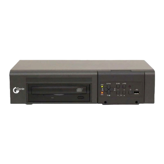
I.CONTROLS 1. Front Panel Built in CD RW or DVD RW 1. Mode Indicator : 2 LEDs display the status of the Digital Video Recorder. Power (Green) and Recording (RED) 2. Playback /Record control: These functions are defined by if it’s in Live Mode or Playback mode. - Page 11 [Time Search/ Playback Stop] ① Time Search : This button accesses the time search menu. Use the directional buttons to select the date and the time. Press [Enter] button to start the playback of the selection. ② Stop: This button stops playback [REC/ R step or FR] ①...
-
Page 12: Rear Panel Connectors
2. Rear Panel Connectors 4-Channel 8-Channel 16-Channel DIGITAL VIDEO RECORDER... - Page 13 1) Camera Inputs: BNC input connectors 2) Spot out connector 3) Composite Monitor Output: BNC standard composite video output connector. 4) AUDIO Input /Output connectors: RCA 5) VGA out connector 6) RJ-45 Ethernet Port(Lan): For connecting to remote PC via Ethernet network. 7) RS-232C [D-SUB 9PIN] : Development purposes only.
-
Page 14: Remote Controller
3. Remote Controller DVR ID EXT. SEARCH TIME SEARCH INFORMATION BACK UP DISPLAY MODE PAN/TILT/ZOOM ENTER CANCEL / OSD OFF ZOOM MENU - BUTTON REWIND + BUTTON FAST FORWARD STOP SCHEDULE REC ON/OFF PLAY RECORD STEP NUMBERS & ALPHABET * <note> “Ext Search” is not supported by this model DIGITAL VIDEO RECORDER... -
Page 15: Virtual Keypad For Mouse Control
4. Virtual Keypad for Mouse Control. This DVR can be controlled by Mouse. Connect a mouse via USB port before use. If you click right button of your mouse in Live mode and Playback mode, you will see following virtual Remote controllers respectively and Virtual Keypad will be shown to enter PASSWORD and Camera Name etc. -
Page 16: Installation & Connections
II. INSTALLATION & CONNECTIONS 1. Camera, Monitor, Microphone, Alarm sensor and Power cord SENSOR Up to 4 cameras CAMERA#1 PC MONITOR PAN/TILT CAMERA MONITOR1 MONITOR2 <Example of 4CH > * RS-422 Connection 1) TX + - : Connect to PTZ camera 2) RX + - : Connect to box of Controller (DVR +-) . -
Page 17: Hdd Connection
2. HDD Connection Please ensure that the HDD is firmly connected with the HDD Rack Bay. <Jumper> 1) The jumper pin setting of the HDD must be set to Master. For HDD’s pin settings, please refer to your HDD’s manual. Firmly connect the HDD into the HDD Rack Bay. -
Page 18: Pc System Requirement For Network Connection
3. PC system requirement for Network connection. (a) Pentium-4 2.0GHz or Higher (b) 256MB RAM (c) Windows 2000, ME, Windows XP (d) 16MB Video Card (e) Spare 10/100-BaseT Ethernet Port (f) RJ-45 Network Cable (g) CAT-5 UTP Cable for LAN (Crossover cable for direct connect to PC) <Disclaimer>... -
Page 19: Iii.quick Start Page
III.QUICK START PAGE The Factory Default password for the unit is “000000” The Default password to run the CMS software is “0” DIGITAL VIDEO RECORDER... - Page 20 Time & Date Setting When the DVR is powered on for the very first time, the time and date are set as default to January 1, 2006 Sunday 01:00:00. Before any other operation of the Digital Video Recorder, it is important to setup the time and the date.
-
Page 21: Iv.live Viewing
IV.LIVE VIEWING 1. Display Overview Recording Mode Event Indicator Camera No and Title Status (1) Indicate Alarm In terminal is triggered by an alarm sensor. To disappear, press [CANCEL] button. (2) Indicate Motion detected. To disappear, press [CANCEL] button. (3) Indicate Video Loss during Recording. To disappear, press [CANCEL] button. (1) (2) (3) (4) (5) (6) (1) Indicate Built-in CD R/W is connected. -
Page 22: Muliscreen Display And Sequencing
2. Muliscreen Display and Sequencing 2.1 Screen Display. Select any camera for Full screen display by pressing the Number button of the desired camera. 2.2 Multiscreen Display and Sequencing Display. Press [DISPLAY] buttons to activate the multiscreen display. It is changed the order as shown below among your choice of SPLIT MODE. -
Page 23: Quick Button For Multi Screen Display
3. Quick button for multi screen Display. 1) Press F1 button on the remote controller + <Number> For example, press F1 button then number 8. The eight channel view mode will be displayed. <Note> 6,4,8,10,13 split mode must be checked on <Spit mode> to use this function. -
Page 24: Zooming
4. Zooming During live view mode or playback, it is possible to zoom into a section of the screen to get a close-up view of the screen. 1. To activate the digital zoom, select the full screen display of the camera you wish to zoom. -
Page 25: Operation
V. OPERATION 1. Main Menu Overview When the DVR is powered on, Live Viewing screen will appear after initialization about 30sec. Press [MENU] button to access the main menu. An Admin Password Box will appear. Enter the password using Numeric buttons on IR remote controller or CH increase button on Front Panel. -
Page 26: Display Option
2. Display Option 2.1. Display Setup 1. Use Direction buttons [ ] to select “DISPLAY” menu. Then, press [ENTER] button to display “DISPLAY SETUP”. 2. Use Left/Right buttons [ ] to select on TAP menu ( Selected items changed [ORANGE] color.. 3. -
Page 27: Sequential Setup (Auto Sequence)
2.2. Sequential Setup (Auto Sequence) ITEM DEFAULT ADJUSTMENT SEQ. 5 Sec Specify the dwell time of each camera or Muliscreen mode is INTERVAL [-, +] button : displayed. Use [1 second ~ 30 second] SEQ. MODE None Select desired sequence mode to switching. Select the cameras to be included or excluded from the FULL SCREEN automatic sequencing. -
Page 28: Camera Setup
3. Camera Setup Use Direction buttons [ ] to select “CAMERA” menu. Then, press [ENTER] button to display “CAMERA”. 2. Use Left/Right buttons [ ] or Number button to select the Camera you wish to configure. 3. Use Down [ ] button to move specified menu and use Left/Right buttons [ ] to select other item. - Page 29 1st Press 2nd Press 3rd Press 10/0 SPACE <Insert characters from IR Remote Controller > DIGITAL VIDEO RECORDER...
-
Page 30: Motion Recording
4. Motion Recording 1. Use Direction buttons [ ] to select “MOTION” menu. Then, press [ENTER] button to display “MOTION”. 2. Use Left/Right buttons [ ] or Number button to select the Camera you wish to configure. 3. Use Down [ ] button to move specified menu and use Left/Right buttons [ ] to select other item. - Page 31 Use <+> button to select Motion Grid at Front Panel . Running Man Icon will be activated. <+> button is used for selecting and cancel. Use <-> button to escape from Grid Menu. It is also possible to select smaller motion grids for more precise motion detection by using CMS.
-
Page 32: Basic Recording (Normal Recording)
5. Basic Recording (Normal Recording) The DVR comes with a certain preset settings from the factory. Therefore once the DVR is installed, immediate recording is possible after pressing the record buttons. By default, audio alarm, motion recording are off. 1. Use Direction buttons [ ] to select “RECORD”... - Page 33 7. To Record stop, press the “ STOP” button on IR remote or [REC] button again on Front Panel. <Note> Estimated Recording Time varies due to picture quality and capture rate and is updated every 10 seconds due to variation of picture size. <...
-
Page 34: Alarm Recording
6. Alarm Recording Please verify the alarm record settings prior to starting alarm recording. Please note that alarm recording is independent of any recording modes. Alarm record starts after Alarm Record Enable. 6.1. Record Setup Use Direction buttons [ ] to select “ALARM” menu. Then, press [ENTER] button to display “Alarm Record Setup”. -
Page 35: Alarm Setup
6.2. Alarm Setup ITEM ADJUSTMENT Determines the duration of recording after the alarm signal has been RECORD TIME activated. [10SEC ~ 300SEC] ALL: Start to record All Alarm “ON” channel if there is any Alarm signal is RECORD CAMERA triggered. 1:1: Start to record the channel, which Alarm is triggered. -
Page 36: Alarm Record Enable
6.3. Alarm Record Enable Select the usage of the Alarm Record. Mode 1~4 means for Schedule recording Mode 1~4 Schedule <Example 1> RECORD Alarm Resulting Actions Normal Motion Normal Press the REC button, then Alarm recording starts according to configured Recording Quality (Super), Frame Rate (15F/S) and Audio when Alarm is triggered. - Page 37 <Example 2> RECORD Alarm Resulting Actions Normal Motion Normal Press the REC button, then Normal recording starts with High picture quality at 3F/S without Audio. When Alarm is triggered on this channel, it changed to record with Super picture quality at 15F/S with Audio. It will be back to Normal Recording after Alarm recording duration time is end.
-
Page 38: Schedule Recording
7. Schedule Recording The schedule chart shows a graphical representation of the defined record mode: Mode1~4. However, the schedules are only displayed if a corresponding schedule has been configured in the schedule menu. 1. Use Direction buttons [ ] to select “SCHEDULE” menu. Then, press [ENTER] button to display “Schedule Chart”. - Page 39 5. Enter the beginning and end time, then select Record mode to record. (1) BEGIN: The time of recording start. (2) END: The time of recording end. The ending time must not be before the starting time or the same as the starting time. It must be any time over the starting time. (3) MODE: Up to 4 different recording modes can be pre-determined for schedule recording.
-
Page 40: Summary Of Combination
Summary of combination RECORD ALARM SCHEDULE RECORD MODE MENU CAMERA USE MOTION Normal Mode1~4 MODE 1~4 CAMERA USE Normal RECORD Motion RECORD Alarm ALARM Schedule SCHEDULE Schedule Motion SCHEDULE Normal and Alarm RECORD & ALARM Motion and Alarm RECORD & ALARM Schedule and Alarm ALARM &... -
Page 41: Network Setup
8. Network Setup The static service consists of an IP address that remains constant for the duration of the contract of the internet service, whereas the dynamic service consists of an IP address that frequently changes every time a new connection is made through the provided modem, or recurrently in a given period of time. - Page 42 How to connect the DVR via Network to use DDNS <Note> 1. Select DHCP. Dynamic IP Router 2. Please check “Serial No” on System Menu. 3. Enter DNS name<ex: http://L10020E.dvrhost.com:7000> on Web browser or CMS. DIGITAL VIDEO RECORDER...
-
Page 43: E-Mail
8.2. E-Mail The DVR is capable of sending e-mails when an event occurs to up to 5 different e-mail addresses: Alarm, Video Loss, Power Loss (when power recovered), HDD Failure. There are two types of sending e-mail method; Using “Unique” or “Public/ your own mail server”. - Page 44 8.3 DDNS ITEM ADJUSTMENT OFF : NO use of DDNS DEFAULT : use default “dvrhost.com” domain name. If your DVR’s host name(SYSTEM >INFO) is L50AD25, Your DVR’s DDNS address is http://L50AD25.dvrhost.com:portNO DYNDNS : to use “Dyndns.com” domain. Domain Name Enter your domain name if you use “Dyndns” or your own Domain. User ID Enter user ID for DDNS.
-
Page 45: Misc
8.4. MISC. ITEM ADJUSTMENT BANDWIDTH “Unlimited” is set by default. Select “64 KBPS ~ 8 MBPS” PING BLOCK No response for ping. Default by OFF SCAN BLOCK No response for Auto Scan from CMS. Default by OFF DDNS Update Response for call DDNS. Default by ON DIGITAL VIDEO RECORDER... -
Page 46: System Setup
9. System Setup 9.1. General 1. Use Direction buttons [ ] to select “SYSTEM” menu. Then, press [ENTER] button. 2. Use Left/Right buttons [ ] to select on TAP menu 3. Use Down button [ ] to specify the detail. Use [-, +] button to change the value. -
Page 47: Time
picture. If you tick “Normal Recording”, the unit will save the previous recording setup value after Rebooting. For example, you shutdown the DVR in this “Normal RUN ON BOOT Recording” mode, the unit will be still in recording mode when you turn on the DVR. -
Page 48: Account
9.3. Account Admin can define each user’s Authority. Select User 1~5 , then select Activate option on or off. When enabled, it will be possible to check individually under user settings: Monitoring, Playback, Back up, Network, Configuration (Main Menu Setup), Shutdown (Power off). Enter the 6 numbers for the new password, and then re-enter the same password under COMFIRM section. -
Page 49: Disk
9.4. DISK ITEM ADJUSTMENT 1. Stop the DVR completely before the disk format. 2. Use [-, +] button to change select device.. Internal HDD, RACK-CD/RW or DVD RW, USB (Front), USB(Rear) 3. Use down button [ ] to move , then press [“+” or “ –“] button FORMAT to start formatting. -
Page 50: Update
9.5. UPDATE. 1) Download the latest firmware file and copy to USB Flash memory stick in the Root Folder. (I mean do not make a special folder into memory stick for these files.) <NOTE >: Please make sure if you download all of files below (10M). m2k_all.00.00.00.img 2) Turn on the S sereis (If you are using, please stop the recording) 3) Plug into Front USB. -
Page 51: Info
9.6. INFO Press info button on IR remote to display the information. The other menu is blocked to move. This menu provides information such as listed below. Indicator CONDITION MODEL Display Channel Number and compression. HOSTNAME. Display hostname and Mac Address. LANGUAGE Display the language of this unit. -
Page 52: Vi.pan/Tilt Zoom Control
VI.PAN/TILT ZOOM CONTROL 1. P.T.Z .Menu To activate the Pan/Tilt Control, select the full screen display of the camera you wish to control. Then press the [ ] button. Shortcut Menu box pops up, as shown below. P/T/Z/FOCUS <Note > Please Refer to Help Menu for specific control. INDICATOR RESULTING ACTIONS Press this button to display “HELP”... -
Page 53: Preset & Tour
The layout of the PTZ interface conforms to the layout of the front of the DVR or the remote controller. Menu button is the guide anchor position for all other buttons. When in PTZ interface mode, all buttons used for the PTZ related operation. ** Please Check below items before using PTZ Camera. - Page 54 4. PTZ Camera Model - PAN/TILT/ZOOM Camera List Esc/ Model Name Speed Preset Go to Tour A. Pan A.Tilt Enter NUVICO, NV 9600 BPS MERIT LILIN, PIH- 7000/7600 VCL, Orbiter Microsphere SAMSUNG, SCC-641 NEC, NC-21D SUNKWANG, SK2107 RESERVED D-MAX, PTZ PROTOCOL LG, LPT-A100L P/T/Z HONEYWELL, GCC- 655N...
- Page 55 ELMO, PTC-200C/400C NICECAM, MP-1xxx C&B TECH, CNB- PTZ102 <Note> Speed has 0~8 steps 1 (Slow) – 8 (Fast) * 0 – Keep Pressing the button to increase speed DIGITAL VIDEO RECORDER...
-
Page 56: Vii.search/ Playback
VII.SEARCH/ PLAYBACK 1.Time Search 1. To start playback, press [Time Search] button, Time search Calendar Menu pops up, as shown below. 2. Use Left /Right button to change select Month on <Note> It will not be changed if there are no stored data on previous/next month. <Note>... -
Page 57: Log List Search/Alarm, Motion Search
2.Log List Search/Alarm, Motion Search The logs can be used to search and review directly to a point in time of the recorded data. Alarm, motion, video loss and system related logs can be searched and played back directly from the time of the incident. To start Event Search, press [Log] button on IR Remote, then Log List Menu 1. -
Page 58: Viii.backup
VIII.BACKUP 1. Internal CD R/W For convenience, this has a built-in CD-RW where the backup can be made easily. Moreover, any backup CD can be read from the CD-RW for reviewing the backup data. 1. Insert a blank Media into Built-in CD. <Note>... - Page 59 The progress of the backup will be displayed at the bottom of the window in percentages of the entire backup process. Please note that the internal CD-RW icon’s color will change to blue to signify that backup is in progress. The OSD will be disappeared by pressing cancel button.
-
Page 60: External Usb Memory Stick
* The CD Playback software will simply “auto-run” and does not require the installation of software on you PC Channel Select FF/FR Watermark Stop Play <Note> Please Refer to [LOCAL PLAYER] section to read Back-up Device. <Note2> When you back up as Muli-Section, Play List will be pop up instead of Auto Run. 2. -
Page 61: Back Up Range Setup
3. Back up Range Setup It is possible to set up backup range automatically on Time Search Menu[by Month, Date, Hour, Minute] Press [-] button to set backup Start time , press [+] button to set End. Selected time will be changed [Light Grey] Color. -
Page 62: Ⅸ.client Program
Ⅸ.CLIENT PROGRAM - Central Management Software DIGITAL VIDEO RECORDER... -
Page 63: Installation
1. Installation PC system requirement Minimum Recommended Windows 98SE, 2000, ME, XP Windows XP Pentium II Celeron 333 Pentium 2.8 G Ⅳ 128MB 512MB RAM 16MB Video Card 20MB 2 GB HDD Free Space 1024*768 1024*768 Resolution Direct X 6.0 or higher Direct X 8.0 or higher Overlay YUY2 Surface Supported If the PC does not meet the minimum system requirement, the CMS program may not function... -
Page 64: How To Install
1.2. How to Install (1) Insert “Client Install CD” to CD-ROM of your PC and Find “DvrPlayerinstaller.exe” and double click (2) Click 「NEXT」 button below: (3) Click 「Install」. Otherwise, designate a directory for Install then Click “Install”. (4) Click 「Close」Button after below images appears. (5) The ICON of CMS will be displayed on your desktop. - Page 65 (6) Double click the ICON to start, enter the password to access. * Enter “0” as the default password. Refer to CMS Setup to change the password. To get rid of this screen, Press “ESC” DIGITAL VIDEO RECORDER...
-
Page 66: Features
2. Features 2.1. CMS Overview Multiscreen selection Current CMS Mode Time and Date Live /PB mode Switch Quick Button Playback Button Pan/Tilt Control Power ON/OFF Health Report DVR Window Virtual DVR Window Add/Delete DVRs Live Viewing Camera CH No. Audio Volume 2.2. - Page 67 It shows you current time on LIVE Mode and Playback time on PB mode. Month Date Day of Week Hour Minutes Seconds (3) Live /Playback mode Switch LIVE Viewing. Remote Playback or Playback for Downloaded file. (4) Quick Button Save the current live images. When the remote recording is in progress, the record button will change its color to cyan.
- Page 68 * CMS Setup ① General 1 a) OSD SETUP Select On-Screen-Display information such as the Time, DVR name, Camera Number, Camera Name, Frame Rates for each camera. b) OVERLAY (Default) It is recommended to use OVERLAY for transmission speed up. Please cancel the Overlay function if there is broken screen caused by Invalid Video Driver installed.
- Page 69 GENERAL 2 ② a) POS Setting to limit the POS item search. <Not supported this model> b). Log Setting to limit the Display of Logs. c). Check Watermark Setting to check for watermark. d) Auto Full Screen for Alarm Event Setting to perform a full screen pop-up for alarm event.
- Page 70 ④SOUND Audio alert setting for the CMS. You can toggle to enable the sound or to disable the sound from the software. • Connect: CMS will emit a sound when a DVR connects. • Disconect: CMS will emit a sound when a DVR disconnects. •...
- Page 71 PAN/TILT Control button. Switch to Full Interface Switch to Compact Interface Zoom IN Zoom Out If one or more Pan/Tilt/Zoom Cameras are installed on the DVR, they can be individually selected and controlled using the PTZ control box. To control a channel-specific PTZ camera, simply click on the channel where the PTZ camera is connected.
- Page 72 c. Iris Indicator Resulting Actions Iris Open Iris Close Iris Auto d. Tour Indicator Resulting Actions Set Tour by clicking. Total address is depends on connected Pan/Tilt Camera. Go To, Calls up preset Start Automatic Tour e. Special Function Key It has various function depends on PTZ camera f.
- Page 73 HEALTH Displays the name of the last five DVRs with an problem or event. The color will change appropriately based on the event or problems reported from the DVR. The color changes to red when critical functions of the DVR is interrupted or has failed: Connection Fail, Connection time out, Disconnect Power Fail, Fan Lock, System Fail, HDD Fail, Power Fail Recover, Fan Lock Recover, System Fail Recover, HDD Fail Recover...
- Page 74 * Health Report Health Report menu is provided so that users may quickly overview all the condition of connected DVR. You can check maximum 300 DVR statuses such as Failure, Event, Recording Mode and etc Health Report can be accessed at any time by double-clicking “HEALTH”. The detail log lists can be showed by double clicking Name on Health Report or ICON on DVR Window.
- Page 75 ** DVR Property The Property of DVR can be viewed by Double Click “DVR NO or DVR NAME”. This menu provides information such as listed below. a. DVR MODEL b. SYSTEM TIME: Display the time and date of DVR c. RECORD : Configure current Normal recording channel.
- Page 76 ** CMS LOG LIST This menu provides CMS log while CMS is operating. For more specific information for each DVR, please refer to DVR Log list. ** DVR LOG LIST - It shows the same log list with DVR Set. It has a list of all the events since the initial power on procedure of DVR.
-
Page 77: Dvr Control
3. DVR Control 3.1. Set List Manager - Set List Manger is mainly used to add or delete DVR on CMS. Click button to start the Set List Manager. (1) Auto Scan It automatically tracks down DVRs connected local network but skips over already on the list. - Page 78 (3) DEL FROM LIST: Delete selected DVR from CMS List. (4) SETUP: It shows the menu setting of selected DVR. (5) PROPERTY: This menu provides information such as DVR Name, IP number & port, Software version, and what kind of DVR is. DIGITAL VIDEO RECORDER...
-
Page 79: Condition Of Dvr
3.2. Condition of DVR The condition of DVR menu is provided so that users may quickly check the condition of each connected DVR. Each Icon means listed below. (1) Normal Blue colored DVR means the DVR is working without any problem. When you click this icon, it displays current live view. -
Page 80: Indication Of Camera
3.3. Indication of Camera In addition to the Health Status Report and supplementary information from the DVR icons in DVR window, the Camera Status Bar displays the status of individual cameras. The cameras are displayed according to the channel. (1) Click the desired DVR (2) then it shows the information of camera. -
Page 81: Live Viewing
3.4. Live Viewing Individual DVR monitoring Double click “ “ to display live. (2) On-Screen Indicators There are four types of on screen indicators. OSD Display can be chosen in the CMS Set UP. ② Time ① Camera Title ③ DVR status ④Frame Rate 1) Camera Title: Displays the following orders: Camera Number- DVR Name or Host Name -Camera title... - Page 82 (3) Multiscreen Display Click the individual Multiscreen buttons to display corresponding multiscreen. (4) Change the camera position. Click on each camera to directly switch the desired camera. (5) Full Screen Display There are 2 way of Full Screen display. 1) Select any camera for Full Screen display by double clicking the window of desired camera.
-
Page 83: Context Menu
3.5. Context Menu The context menu allows access to the submenus for the channel, DVR and the Virtual DVR. The submenus allow access to various features for each individual submenu type. (1) There are three types of Context Menu during Live Viewing. Right Clicking to display Context Menu. - Page 84 (2) There are seven types of Context Menu on each DVR. 1) LIVE: Live display for selected DVR. 2) PROPERTY: DVR information 3) CMS LOG LIST 4) DVR LOG LIST 5) SETUP: See “DVR Menu Setup” 6) REMOVE: Delete the selected DVR from DVR Window. DIGITAL VIDEO RECORDER...
-
Page 85: Playback
3.6. Playback DVRs that have been added onto the DVR window using the DVR Set List Manager can be accessed in Playback Mode for remote playback or to download the files onto the remote PC. Unlike the live mode, only one DVR can be accessed at a time (1) To start playback, press PB button (2) It will be switched to Playback Mode, as shown below. - Page 86 1) Remote Playback Remote Playback is provided so that users directly playback the stored video on the internal HDD through CMS. ① Select button and desired DVR. ② Remote Search shows a graphical representation of the recorded video stored on the DVR. The Data are color-coded by category: Alarm(Red) > Motion(Green) >...
- Page 87 Remote Download Remote Download is provided so that users save on remotely connected computer through CMS. ① Select button and desired DVR. ② Remote Search shows a graphical representation of the recorded video stored on the DVR. ③ Select desired date and time and click button to start save.
- Page 88 Download Complete: Current time will be changed to message “ Download Complete” after the download has been completed, as shown below. Click LOCAL Local Menu is mainly used to review the data downloaded from a DVR through CMS. ① Select button.
-
Page 89: Dvr Menu Setup
3.7. DVR Menu Setup -DVR Menu Setup allows modification of various system settings to the DVR through CMS as it would be done accessing the DVR menu screen. - DVR set up can be accessed through the context menu from any DVRs Select any DVR for Menu setup. -
Page 90: Virtual Dvr
4. Virtual DVR 4.1. What is Virtual DVR. Virtual DVR is not an actual DVR, but a combination , or group of several DVRs already listed under the DVR window. Under one Virtual DVR set, up to 64 DVRs can be added, pulling one camera from each DVR to be displayed. - Page 91 (1) ADD to CMS List Please follow steps to Make Virtual DVR. 1) NAME: Enter Virtual DVR title to display on CMS window. * Auto Arrange : - Check this option to have the CMS arrange cameras with any of the events occurring from a virtual DVR with registered cameras.
-
Page 92: Editing Virtual Dvr
4.3. Editing Virtual DVR Double click the desired Virtual DVR . The selected Virtual DVR will be activated and it is indicated with “ “ ▷ Select any of Multiscreen to Display. There are two way to add cameras: one is Whole DVR and the other is selected camera on each DVR. 1) Whole cameras of desired DVR . -
Page 93: Live Viewing On Virtual Dvr
2) Any selected camera on DVR. Click any D VR on DVR Window while Virtual DVR is activating. ① After camera Icons diplyed, any camera on DVR to directly drag the desired channel. ② In the following exampels, Camera No 1 on 3 DVR is draged to Channel No 14. -
Page 94: Appendix 1: View Only
Appendix 1: VIEW ONLY Enter the IP address of the unit in the address page of the Internet Explorer. For example, type in http://192.168.0.250:7000 Above illustrates example of a unit when it is utilizing port 7000. You can either sign in with: admin or user. Next enter the password for the unit. - Page 95 DIGITAL VIDEO RECORDER...
- Page 96 Specifications 16CH Video Input/ Loop Out 16 /0 Video Output Monitor, VGA, SPOT-OUT Compression MPEG 4 Live Display Resolution NTSC 720*480, PAL 720*576 Alarm In/Out(Relay) Operating System EMBEDDED LINUX System Control Key buttons, IR Remote, Remote Client, Keypad Live Display Speed 4/8/16 CH Real Time NTSC 30 fps 720*480 ,60 fps 720*240, 120 fps 360*240...
- Page 97 WEEE Symbol Information Correct Disposal of This Product (Waste Electrical & Electronic Equipment) (Applicable in the European Union and other European countries with separate collection systems) This marking shown on the product or its literature, indicates, that it should not be disposed with other household wastes at the end of its working life.
- Page 98 <Memo> DIGITAL VIDEO RECORDER...
- Page 99 GENIE CCTV LTD. CCTV House, City Park, Watchmead, Welwyn Garden City, Hertfordshire, AL7 1LT Tel: +44(0)1707 330541 Fax: +44(0)1707 330543 www.geniecctv.com DIGITAL VIDEO RECORDER...
Need help?
Do you have a question about the EDVR-4 and is the answer not in the manual?
Questions and answers