
Subscribe to Our Youtube Channel
Related Manuals for Icom AH-740


Summary of Contents for Icom AH-740
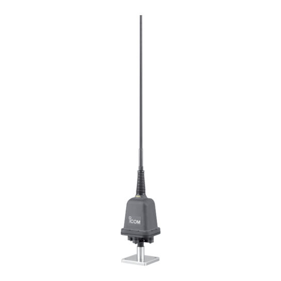
- Page 1 INSTRUCTION MANUAL HF AUTOMATIC TUNING ANTENNA AH-740 * The “stand” in the photo is not supplied with the tuning antenna.
-
Page 2: Foreword
Covers 2.2 to 30 MHz range when using ❍ tions. with the optional NVIS kit Icom, Icom Inc. and the Icom logo are registered trademarks of Icom Incorporated (Japan) in Japan, the United States, the United King- dom, Germany, France, Spain, Russia and/or other countries. -
Page 3: Table Of Contents
INSTALLATIONS ..............2 Typical installation scenarios ……………………………… 2 ■ DO NOT use the AH-740 in areas where the temperature is Precautions when the optional AH-5NV is installed on a below –40°C (–40ºF) or above +70°C (+158ºF). vehicle………………………………………………………… 3 Installation outline …………………………………………… 4 ■... -
Page 4: Supplied Accessories
!0 Nut (M16) ..............1 !1 Flat washer (M16) ............1 MISCELLANEOUS ITEMS The following items are additionally required for installation, but is not supplied with the AH-740. Purchase the item locally. • Mounting base • Rubber vulcanizing tape • Electrical tape... -
Page 5: System Installation
■ ■ It is absolutely essential that the antenna is connected to Insulate the lead-in cable of the AH-740 antenna terminal and an effective and stabile RF GROUND POINT— the vehicle antenna element from other metal objects. To prevent interfer- chassis. -
Page 6: Installations
INSTALLATIONS Typical installation scenarios ■ Most recommended SUV installation scenarios use a Uni- Recommended installation options on a typical sedan vehicle versal Gibbet Mounting System (front) or the Spare Wheel use a Universal Gibbet Mounting System for both front and Antenna Bracket (rear). -
Page 7: D Precautions When The Optional Ah-5Nv Is Installed On A Vehicle
INSTALLATIONS For best communications, position the antenna as high as What is NVIS? possible. The Figure 1 shows the preferred option selection. NVIS stands for Near Vertical Incidence Skywave. The Figure 2 shows an antenna installation that uses the op- The NVIS radio-wave propagation provides usable signals tional AH-5NV, for best communications on the 30–300km between groundwave and skywave distances. -
Page 8: Installation Outline
■ RWARNING! IMPORTANT! Mount the AH-740 securely with the supplied nuts and bolts. Otherwise, vibrations and shocks due to rough The antenna is a critical element in any communication sys- terrain could loosen the antenna. It could fall, causing per- tem. -
Page 9: Cable Connections
• See the transceiver instruction manual for details. The antenna tuner connections in the manual are the same as for the AH- Ground 740. strap Ground the transceiver, AH-740 and shield cable of the control cable to the ground terminal. Vehicle chassis or body... -
Page 10: Optional Ah-5Nv
INSTALLATIONS Optional AH-5NV ■ When using the AH-740 with the optional AH-5NV, install the Place the swivel magnet holder onto the vehicle, and at- AH-5NV as follows. tach the NVIS antenna element to the antenna spring of the AH-740. • Secure the antenna element by tighten the set screws. -
Page 11: Specifications And Options
Icom product. or obligation. Icom is not responsible for the destruction or damage to an Icom product in the event the Icom product is used with equipment that is not manufactured or approved by Icom. - Page 12 A-7088H-1EX Printed in Japan 2013 Icom Inc. © 1-1-32 Kamiminami, Hirano-ku, Osaka 547-0003, Japan...
Need help?
Do you have a question about the AH-740 and is the answer not in the manual?
Questions and answers