Advertisement
ANTENNA MATCHERS
MN-100 MN-100L
(for 1.5 MHz to 30 MHz)
■ Profile
To put a full size antenna on a yacht or boat is very difficult.
However, these antenna matchers have been designed to
put an antenna in such restrictions of space, and give low
VSWR with short antenna elements on wide frequency range
of 1.5 MHz to 30 MHz. So, you can obtain the best perfor-
mance from the transceiver.
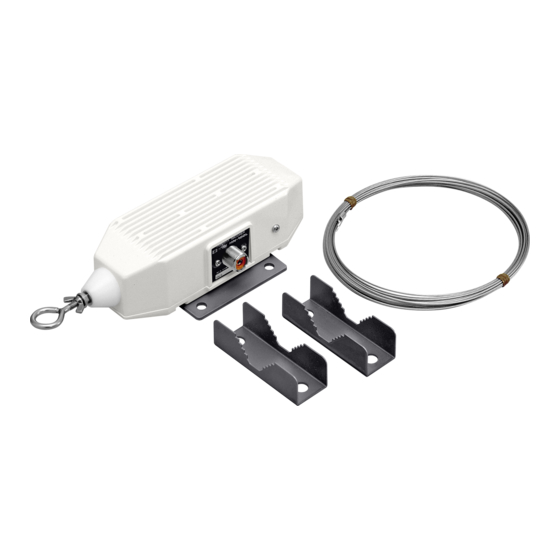
■ Supplied accessories
q Antenna wires
MN-100
MN-100L
w Nuts ����������������������4
e Spring washers �����������������4
r Flat washers ������������������4
t Mast mounting brackets �������������2
y U bolts ���������������������2
u Rubber vulcanizing tape �������������1
i Insulators
MN-100 ������������2
MN-100L ������������1
o Wire clamps
MN-100 ��������� 4 sets
MN-100L ��������� 2 sets
!0 Grounding wire �����������������1
q
i
u
Icom, Icom Inc. and the Icom logo are registered trademarks of Icom
Incorporated (Japan) in the United States, the United Kingdom, Ger-
many, France, Spain, Russia and/or other countries.
INSTRUCTIONS
8 m ���������2
15 m ��������1
w
e
r
t
y
o
!0
Thank you for purchasing this Icom product.
These antenna matchers have been designed for Icom
HF transceivers.
Please read all instructions carefully before installation to
get maximum performance and full value from the trans-
ceiver.
■ Specifications
MN-100
: For dipole or whip antenna
MN-100L
: For whip antenna only
• Max. input power
: SSB
CW
• Frequency range
: 1.5 MHz to 30 MHz
: 50 Ω unbalanced
• Input impedance
• Insertion loss
: Approx. 6 dB
• VSWR
: Less than 2.0 with supplied antenna
wires
• Operating temp.
: –30˚C to +80˚C; –22˚F to +176˚F
• Dimensions
:
Projections not included
180(W)×65(H)×55(D) mm
; 7
3
⁄
32
Projections included
MN-100
310(W)×100(H)×58(D) mm
; 12
7
⁄
32
MN-100L
245(W)×100(H)×58(D) mm
; 9
21
⁄
32
• Weight (approx.)
: MN-100
MN-100L
■ C onnector assembly
instructions
q PL-259 connector is not supplied with the MN-100/L, so
please prepare suitable connector for the coaxial cable
you desired to use.
w Cut end of the cable evenly. Remove vinyl jacket 29 mm
(1
1
⁄
˝). Please do not nick the braid.
8
e Bare 15 mm (
5
⁄
˝) of the center conductor without nicking
8
the conductor. Trim braided shield 14 mm (
Slide the coupling ring on the cable.
r Screw the plug assembly on the cable. Solder plug as-
sembly to the braid through solder hies. Solder the con-
ductor to the contact sleeve. Screw the coupling ring on
the assembly.
t Attach it to the connector of the MN-100/L, and cover the
connector with the supplied rubber vulcanizing tape.
200 W pep
100 W
(W)×2
9
⁄
(H)×2
5
⁄
(D) in
16
32
(W)×3
15
⁄
(H)×2
9
⁄
(D) in
16
32
(W)×3
15
⁄
(H)×2
9
⁄
(D) in
16
32
1.27 kg; 2 lb 13 oz
1.23 kg; 2 lb 11 oz
9
⁄
˝) and tin it.
16
Advertisement
Table of Contents

Subscribe to Our Youtube Channel
Related Manuals for Icom MN-100


Summary of Contents for Icom MN-100
-
Page 1: Specifications
Screw the coupling ring on the assembly. t Attach it to the connector of the MN-100/L, and cover the connector with the supplied rubber vulcanizing tape. Icom, Icom Inc. and the Icom logo are registered trademarks of Icom Incorporated (Japan) in the United States, the United Kingdom, Ger- many, France, Spain, Russia and/or other countries. - Page 2 Attach the MN-100 onto the antenna mast with the sup- w Attach the MN-100/L to a balustrade of the deck or other plied mounting hardware. The mounting hardware is ad- suitable portion of the yacht or boat, where is an adequate justed for 25 mm to 63 mm (1˝...
Need help?
Do you have a question about the MN-100 and is the answer not in the manual?
Questions and answers